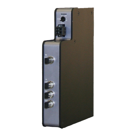
IBA ibaPQU-S User manual

Manual
Issue 1.0
1
ibaPQU-S
Power Quality Measurement Unit according to
IEC61000-4-30 Ed. 3 Class A
Manual
Issue 1.5

Manual
ibaPQU-S
Manufacturer
iba AG
Königswarterstr. 44
90762 Fürth
Germany
Contacts
Head office +49 911 97282-0
Fax +49 911 97282-33
Support +49 911 97282-14
Technology +49 911 97282-13
E-mail: iba@iba-ag.com
Web: www.iba-ag.com
This manual must not be circulated or copied, or its contents utilized and disseminated, without
our express written permission. Any breach or infringement of this provision will result in liability
for damages.
© iba AG 2023, all rights reserved.
The content of this publication has been checked for compliance with the described hardware and
software. Nevertheless, deviations cannot be excluded completely so that the full compliance is
not guaranteed. However, the information in this publication is updated regularly. Required cor-
rections are contained in the following regulations or can be downloaded on the Internet.
The current version is available for download on our web site www.iba-ag.com.
Copyright notice
Windows®is a label and registered trademark of the Microsoft Corporation. Other product and
company names mentioned in this manual can be labels or registered trademarks of the corre-
sponding owners.
Certification
The product is certified according to the European standards and directives. This product meets
the general safety and health requirements.
Further international customary standards and directives have been observed.
Note: This equipment has been tested and found to comply with the limits for a Class A digital device, pur-
suant to part 15 of the FCC Rules. These limits are designed to provide reasonable protection against harm-
ful interference when the equipment is operated in a commercial environment. This equipment generates,
uses, and can radiate radio frequencyenergy and, if notinstalled and used in accordance with the instruction
manual, may cause harmful interference to radio communications. Operation of this equipment in residential
area is likely to cause harmful interference in which case the user will be required to correct the interference
at his own expense.
Issue
Date
Revisions
Chapter
Author
Version HW/FW
1.5
04-2023
Accessories, GUI, FO cable

Manual
Issue 1.5
3
Table of Contents
1About this manual...........................................................................................7
1.1 Target group..................................................................................................8
1.2 Notations....................................................................................................... 8
1.3 Used symbols................................................................................................9
2Introduction ...................................................................................................10
2.1 Modular concept...........................................................................................11
2.2 Measurements according to EN50160.........................................................12
3Scope of delivery...........................................................................................12
4Safety instructions........................................................................................13
4.1 Intended use ............................................................................................... 13
4.2 Special safety instructions........................................................................... 13
5System requirements....................................................................................14
5.1 Hardware ....................................................................................................14
5.2 Software...................................................................................................... 14
5.3 Firmware..................................................................................................... 14
6Mounting, connecting, dismounting............................................................15
6.1 Mounting..................................................................................................... 15
6.2 Connecting..................................................................................................16
6.3 Dismounting................................................................................................16
7Device description ........................................................................................17
7.1 Views ..........................................................................................................17
7.2 Display elements.........................................................................................18
7.2.1 Operating state L1…L4 ............................................................................... 18
7.2.2 LEDs L5…L8...............................................................................................18
7.2.3 Indicators digital inputs L10…L17................................................................ 19
7.3 Operating elements..................................................................................... 19
7.3.1 ON/OFF switch S11..................................................................................... 19
7.3.2 Rotary switches S1 and S2 ......................................................................... 19
7.4 Communication interfaces........................................................................... 20
7.4.1 Fiber optic connections X10 and X11 ..........................................................20
7.4.2 Network interface X22................................................................................. 20
7.5 Digital inputs X5.......................................................................................... 20
7.5.1 Connection diagram / pin assignment..........................................................20
7.5.2 Debounce filter............................................................................................21
7.6 Voltage supply............................................................................................. 24
7.6.1 Voltage supply X14......................................................................................24
7.6.2 Buffer voltage X30....................................................................................... 24
8Measurement principles and measured quantities....................................25
8.1 Grid types.................................................................................................... 25
8.2 Signals and calculated characteristic values ...............................................26
8.3 System integration.......................................................................................28

Manual
ibaPQU-S
4
Issue 1.5
8.4 Time synchronization .................................................................................. 28
8.5 Signal processing........................................................................................ 28
8.5.1 Sampling rate.............................................................................................. 28
8.5.2 Signal filtering ............................................................................................. 29
8.5.3 Automatic range switching .......................................................................... 29
9Updates..........................................................................................................31
9.1 Update via ibaPDA...................................................................................... 31
9.2 Update of the modules................................................................................ 31
10 Configuration with ibaPDA...........................................................................33
10.1 First steps ................................................................................................... 33
10.1.1 Overview of the modules in ibaPDA............................................................ 40
10.2 Basic modules in I/O Manager .................................................................... 41
10.2.1 PQU-S –“General” tab................................................................................ 41
10.2.2 PQU-S –“Analog” tab ................................................................................. 43
10.2.3 PQU-S –“Digital” tab .................................................................................. 43
10.2.4 PQU-S –“Diagnostics” tab.......................................................................... 44
10.2.5 ibaPQU-S –“General” tab........................................................................... 45
10.2.6 ibaPQU-S –“Digital” tab.............................................................................. 46
10.2.7 ibaPQU-S –“Status” tab.............................................................................. 47
10.2.8 Diagnostics - “General” tab ......................................................................... 48
10.2.9 Diagnostics - “Digital” tab ............................................................................ 48
10.3 Submodules to calculate characteristic values............................................ 50
10.3.1 Grid module ................................................................................................ 50
10.3.2 EN50160 submodule: Power frequency...................................................... 54
10.3.3 Submodule EN50160: Supply voltage variation........................................... 56
10.3.4 EN50160 submodule: Flicker severity......................................................... 57
10.3.5 EN50160 submodule: Supply voltage unbalance........................................ 58
10.3.6 EN50160 submodule: Harmonic voltage ..................................................... 59
10.3.7 EN50160 submodule: Mains signalling voltage........................................... 61
10.3.8 EN50160 submodule: Voltage events.......................................................... 63
10.3.9 Basic submodule......................................................................................... 64
10.3.10 Phasor submodule...................................................................................... 66
10.3.11 Power submodule ....................................................................................... 68
10.3.12 Spectrum submodule.................................................................................. 70
10.3.13 Unbalance submodule ................................................................................ 73
10.3.14 Flicker severity submodule.......................................................................... 75
10.3.15 Aggregation submodule .............................................................................. 77
10.3.16 Commutation notches submodule............................................................... 82
10.3.17 Events submodule....................................................................................... 83
11 Technical data ...............................................................................................85
11.1 Main data.................................................................................................... 85
11.2 Interfaces.................................................................................................... 86
11.3 Digital inputs ............................................................................................... 87
11.4 Grid characteristics ..................................................................................... 88

Manual
Issue 1.5
5
11.5 Dimensions ................................................................................................. 89
11.6 Connection diagram.................................................................................... 93
11.6.1 Pin assignment voltage supply X14.............................................................93
11.6.2 Pin assignment digital inputs X5..................................................................93
11.7 Example for FO budget calculation.............................................................. 94
12 Accessories...................................................................................................96
12.1 Backplane panels........................................................................................96
12.1.1 ibaPADU-S-B4S.......................................................................................... 96
12.1.2 ibaPADU-S-B1S.......................................................................................... 99
12.2 Mounting system for central unit................................................................ 101
12.2.1 ibaPADU-S-B ............................................................................................ 101
12.3 Mounting systems for ibaPADU-S-B4S...................................................... 103
12.3.1 Mounting angles........................................................................................ 103
12.3.2 Mounting panel 19“.................................................................................... 104
12.3.3 Module carrier........................................................................................... 109
12.4 Terminal blocks ..........................................................................................110
12.5 I/O modules iba modular system................................................................111
12.6 FO cards/cables.........................................................................................112
12.7 iba software................................................................................................112
13 Appendix......................................................................................................113
13.1 Calculating characteristic values ................................................................113
13.1.1 RMS (Root Mean Square)..........................................................................113
13.1.2 Rectified value............................................................................................113
13.1.3 Peak value .................................................................................................113
13.1.4 Form factor.................................................................................................113
13.1.5 Crest factor ................................................................................................113
13.1.6 Frequency..................................................................................................113
13.1.7 Harmonics, interharmonics, phase angle....................................................113
13.1.8 THD (Total Harmonic Distorsion)................................................................113
13.1.9 Flicker ........................................................................................................114
13.1.10 Power / Energy...........................................................................................114
13.1.11 Voltage balance / Unbalance......................................................................117
13.1.12 Interference factor......................................................................................118
13.1.13 Commutation notches ................................................................................119
13.1.14 Events....................................................................................................... 120
13.2 Connection examples................................................................................ 122
13.2.1 1-phase..................................................................................................... 122
13.2.2 Star connection......................................................................................... 122
13.2.3 Delta connection ....................................................................................... 123
13.2.4 Connection with instrument transformers .................................................. 123

Manual
ibaPQU-S
6
Issue 1.5
14 Index ............................................................................................................125
15 Certificate ....................................................................................................126
16 Support and contact...................................................................................127

Manual
Issue 1.5
7
1 About this manual
This manual describes the design, use and operation of the ibaPQU-S. For information
on the design, use and operation of the I/O modules, please refer to the dedicated man-
uals.
Note
The documentation for the iba-modular system is part of the data medium “iba Soft-
ware & Manuals”. The documentation is also available at www.iba-ag.com in the
download area.
The documentation of the ibaPQU-S system comprises the following manuals:
ibaPQU-S central unit
The manual contains the following information:
Scope of delivery
System requirements
Device description
Installation/Removal
Start-up
Configuration
Technical data
Accessories
Modules
The manuals of the single modules contain specific information about the module.
For example:
Brief description
Scope of delivery
Product characteristics
Configuration
Description of the functions
Technical data
Connection diagram

Manual
ibaPQU-S
8
Issue 1.5
1.1 Target group
This manual addresses in particular thequalified professionals whoare familiar with han-
dling electrical andelectronic modules aswell as communication and measurement tech-
nology. A person is regarded to as professional if he/she is capable of assessing safety
and recognizing possible consequences and risks on the basis of his/her specialist train-
ing, knowledge and experience and knowledge of the standard regulations.
1.2 Notations
The following designations are used in this manual:
Action
Notations
Menu command
Menu „Logic diagram“
Call of menu command
„Step 1 – Step 2 –Step 3 –Step x”
Example:
Select menu „Logic diagram – Add –New logic
diagram”.
Keys
<Key name>
Example:
Example: <Alt>; <F1>
Press keys simultaneously
<Key name> + <Key name>
Example:
<Alt> + <Ctrl>
Buttons
<Key name>
Example:
<OK>; <Cancel>
File names, Paths
„File name“
„Test.doc“

Manual
Issue 1.5
9
1.3 Used symbols
If safety instructions or other notes are used in this manual, they mean:
The non-observance of this safety information may result in an imminent risk of death
or severe injury:
By an electric shock!
Due to the improper handling of software products which are coupled to input and
output procedures with control function!
If you do not observe the safety instructions regarding the process and the system or
machine to be controlled, there is a risk of death or severe injury!
The non-observance of this safety information may result in a potential risk of death
or severe injury!
The non-observance of this safety information may result in a potential risk of injury or
material damage!
Note
A note specifies special requirements or actions to be observed.
Tip
Tip or example as a helpful note or insider tip to make the work a little bit easier.
Other documentation
Reference to additional documentation or further reading.

Manual
ibaPQU-S
10
Issue 1.5
2 Introduction
ibaPQU-S is a modular system to measure power qualitypower parameters using
ibaPQU-S as central unit.
ibaPQU-S measures raw values such as current and voltage in sync with the grid and
calculates the characteristic values according to IEC 61000-4-30 Ed. 3 Class A. Charac-
teristic values include:
Frequency
RMS and maximum value, rectified value, form factor, crest factor
FFT (harmonics, interharmonics up to 50th order)
THD (Total Harmonic Distortion)
Phase values (U/I phase angle to the reference voltage)
Power values (active power, apparent power, reactive power, cos θ, electric energy,
power factor for individual lines and for the total grid)
Symmetrical components (positive, negative and zero sequence component) and
supply voltage unbalance
Flicker (according to IEC 61000-4-15, short-term, long-term)
Event detection (voltage dip, voltage swell, voltage interruption, rapid voltage
changes, ripple control signal)
In addition, ibaPQU-S calculated the following values:
Commutation notches
Flicker for currents
Symmetrical components (positive, negative and zero sequence component) and
current unbalance
ibaPQU-S is suitable for the following grids:
DC
50 Hz
60 Hz
Modular concept

Manual
Issue 1.5
11
2.1 Modular concept
The modular concept of the ibaPQU-S system is designed on the basis of a backplane.
You can plug on this backplane not only the CPU, but also up to 4 input/output modules.
ibaPQU-S is used as a central unit with integrated measurement and calculation algo-
rithms and additionally features 8 digital inputs. The central unit can be expanded by up
to 4 current and voltage measurement modules.
The following I/O modules support the measurement and calculation of power quality
parameters:
Voltage measurement modules
ibaMS4xAI-380VAC (4 analog inputs for 380 V AC)
ibaMS8xAI-110VAC (8 analog inputs for 110 V AC)
ibaMS16xAI-24V (16 analog inputs for ±24 V)
ibaMS16xAI-24V-HI (16 analog inputs for ±24 V, high impedance)
ibaMS16xAI-10V (16 analog inputs for ±10 V)
ibaMS16xAI-10V-HI (16 analog inputs for ±10 V, high impedance)
Current measurement modules
ibaMS3xAI-1/100A (3 analog inputs for 1 AAC/100 A DC)
ibaMS3xAI-5A (3 analog inputs for 5 AAC)
ibaMS3xAI-1A (3 analog inputs for 1 AAC)
ibaMS16xAI-20mA (16 analog inputs for ±20 mA)
Combination module
ibaMS4xADIO (combination module with 4 analog inputs/outputs and 4 digital in-
puts/outputs each; the 4 analog inputs are supported for the ibaPQU-S function,
voltage or current measurement configurable)
All other I/O modules of the iba modular system are also supported, however, the signals
are only transmitted as raw values.
The raw signals and internally calculated characteristic values are sent to the ibaPDA
data acquisition system via a bidirectional fiber optic connection for visualization and
recording. Signal configuration and characteristic value selection are performed in
ibaPDA. Additionally, ibaPDA allows advanced calculations, configuring event-based
measurements based on triggers or displaying faults using an alarm function.

Manual
ibaPQU-S
12
Issue 1.5
2.2 Measurements according to EN50160
The DIN EN 50160 standard specifies the voltage quality in public supply grids. It defines
features and characteristic values for the supply voltage quality and limit values. The
optional “EN50160” mode in ibaPDA captures all characteristic voltage values defined in
the standard. Beyond the requirements of DIN EN 50160, currents can optionally be
configured for evaluation.
The ibaAnalyzer software is used for measurement evaluation and generation of reports.
Moreover, it is possible to create long-term trending and clearly structured reports that
can be used e.g. to prove compliance with the DIN EN 50160 standard.
3 Scope of delivery
After unpacking, check the delivery for completeness and possible damages.
The scope of delivery comprises:
ibaPQU-S device
Covering caps for FO cables, USB and Ethernet
16-pin connector with spring terminals (digital input channels)
2-pin connector with spring terminals (voltage supply)
Data medium “iba Software & Manuals”

Manual
Issue 1.5
13
4 Safety instructions
4.1 Intended use
The device is an electrical apparatus. It is only allowed to use the device for the following
applications:
measurement data acquisition of voltage and current signals in energy grids
applications with ibaPDA
The device must only be used as described in chapter 11.
The current and voltage range is specified by the I/O modules used.
4.2 Special safety instructions
Warning!
This is a ClassA device. This equipment may cause radio interference in residential
areas. In this case, the operator will be required to take appropriate measures.
ATTENTION!
Observe the safety measures for the I/O modules used!
Strictly observe the operating voltage range!
Never supply the device with a voltage other than 24 V DC ±10%!
Excess voltage may destroy the device!
ATTENTION!
Never insert or remove modules and the CPU at the backplane under live conditions!
Switch off ibaPQU-S or disconnect the power supply before inserting or removing
modules.
Important note
Do not open the device! Opening the device will void the warranty!
Caution!
Make sure that the cooling fins have sufficient ventilation!
Note
Clean the device only on the outside with a dry or slightly damp and statically dis-
charged cloth.

Manual
ibaPQU-S
14
Issue 1.5
5 System requirements
5.1 Hardware
For operation
Power supply 24 V DC± 10 %, 3 A (fully equipped)
Backplane unit, e.g. ibaPADU-B4S (see chap.12, “Technical data”)
For device parameterization and measurements:
PC with the following minimum equipment:
one free PCI slot, or
one free PCI Express slot, or
one ExpressCard(54/34) slot (notebook).
You find suitable computer systems with desktop and industry housing under
http://www.iba-ag.com.
One FO input card type ibaFOB-D (firmware version beginning with D4):
ibaFOB-io-D / ibaFOB-io-Dexp
ibaFOB-2io-D / ibaFOB-2io-Dexp
ibaFOB-2i-D / ibaFOB-2i-Dexp with ibaFOB-4o-D add-on module
ibaFOB-4i-D / ibaFOB-4i-Dexp with ibaFOB-4o-D add-on module
ibaFOB-io-ExpressCard (for notebooks)
FO cable, bidirectional
5.2 Software
ibaPDA beginning with version 6.34.4
5.3 Firmware
ibaPQU-S beginning with version 02.11.014

Manual
Issue 1.5
15
6 Mounting, connecting, dismounting
Caution!
Only work on the device when it is de-energized!
6.1 Mounting
1. Mount the backplane on an appropriate construction.
2. Connect the ground terminal.
3. Plug the device into the left slot.
Make sure that the guiding bolts on the rear side of the device are inserted into the
corresponding holes on the backplane.
4. Press the device firmly against the backplane and secure it with the fixing screws.
5. Remove the covers of the backplane slots in which you want to plug I/O modules.
6. Install one or more I/O modules to the right of the central unit (slots X2 through X5,
freely selectable).
7. Firmly plug the module into the backplane.
8. Screw the module to the backplane using the upper and lower fastening screws.
Important note
Always screw tight the device and the modules. Otherwise, plugging or unplugging the
connectors for the inputs/outputs can cause damage.

Manual
ibaPQU-S
16
Issue 1.5
6.2 Connecting
1. Connect the measuring lines connected to the measuring objects to the I/O module
inputs. Connection principles are described in chapter 8.
2. Use an ibaNet FO patch cable (duplex) to connect the device to the ibaPDA com-
puter:
the RX input (X11) of the device with the TX interface of the ibaFOB-D card in the
ibaPDA computer,
the TX output (X10) of the device with the RX interface of the ibaFOB-D card in
the ibaPDA computer.
3. Once all required cables have been connected, reconnect the central unit to the
power supply.
4. Switch on the voltage supply of the central unit.
6.3 Dismounting
1. Switch off the device.
2. Remove all cables.
3. Hold tight the device and remove the upper and lower fixing screw.
4. Pull the device or the I/O modules off the backplane.

Manual
Issue 1.5
17
7 Device description
7.1 Views
1
2
3
4
5
6
7
8
9
10
11
12
Operating status indicators L1...L4
On/off switch S11
Connector power supply 24 V X14
Indicators digital inputs L10...L17
Connector digital inputs X5
Fixing screws
Indicators L5...L8
Network interface X22 (no function)
Rotary switches S1, S2
System function push button S10 (no function)
Connection FO output (TX) X10
Connection FO input (RX) X11
X23 for service purposes only
X24, X25 USB host interfaces for future func-
tions
X30 buffer voltage connection 6...60 V DC

Manual
ibaPQU-S
18
Issue 1.5
7.2 Display elements
7.2.1 Operating state L1…L4
The operating state of the device is shown by colored status LEDs.
LED
Status
Description
L1
Green
Off
Device down, no power supply
Hardware error
Flashing
(0.5 Hz / 2 s)
Ready for operation
Deviations in the flashing period point out overload or booting
of the device. Booting can take up to 100 s.
Flashing (fast)
(approx. 10 Hz /
0.1 s)
System programming mode
Firmware update active
On
Controller overloaded
L2
Yellow
Off
No calculation
Flashing
Calculation running
L3
White
Off
No FO signal detected
Flashing
FO signal detected, configuration error, the received ibaNet
protocol does not match the internally configured protocol
On
FO signal detected
L4
Red
Off
No error
Flashing
Malfunction, internal applications do not run
On
Hardware error
Important note
When the LED L4 indicates an error, please contact the iba support.
7.2.2 LEDs L5…L8
The LEDs L5 through L8 show status and progress when installing an update, see chap-
ter 9 “Updates”.

Manual
Issue 1.5
19
7.2.3 Indicators digital inputs L10…L17
The green LEDs indicate whether a digital input is active or not.
LED
Status
Description
L10…L17
On
Off
Signal ok, logical 1
No signal, logical 0
For further information, see chapter 7.5 ”Digital inputs X5”
7.3 Operating elements
7.3.1 ON/OFF switch S11
Position
Status
Description
I
0
On
Off
Device switched on
Device switched off
By switching the device off and on again, the supply voltage is disconnected and re-
connected and the device is rebooted.
7.3.2 Rotary switches S1 and S2
The rotary switch S1 is used to set the device address. Two devices can be con-
nected to a ring using the 32Mbit Flex protocol.
Device number in the
ring structure
Position of rotary switch S1
Not allowed
0
1. Device
1
2. Device
2
S2 is not used (should be zero).
Important note
Unlike other iba devices supporting the 32Mbit Flex protocol, it is only allowed to oper-
ate two ibaPQU-S systems in cascade configuration at one free 32Mbit Flex link of an
ibaFOB card due to the high sampling rate of 10 - 40 kHz and the high data volume in
the network channel of the Flex protocol.
Important note
When starting up the device for the first time, check the status signals of ibaPQU-S
(data loss etc.). If multiple signals occur, the time base of the system has to be ex-
tended.

Manual
ibaPQU-S
20
Issue 1.5
7.4 Communication interfaces
7.4.1 Fiber optic connections X10 and X11
The FO cables transmit the process data between the device and the connected iba
systems. The 32Mbit Flex transfer protocol also allows configuration data to be trans-
ferred via FO cable.
Connection
Description
X10 output (TX)
FO send interface
X11 input (RX)
FO receive interface
Maximum distance of fiber optic connections
The maximum distance of fiber optic connections between 2 devices depends on various
influencing factors. This includes, for example, the specification of the fiber (e.g.
50/125 μm, 62.5/125 μm, etc.), or the attenuation of other components in the fiber optic
cable plant such as couplers or patch panels.
However, the maximum distance can be estimated on the basis of the output power of
the transmitting interface (TX) or the sensitivity of the receiving interface (RX). A model
calculation can be found in chapter 11.7.
The specification of the transmitter's output power and the receiver's sensitivity of the
fiber optic components installed in the device can be found in chapter "Technical data"
11.2 under "ibaNet interface".
7.4.2 Network interface X22
Ethernet interface 10/100 Mbit/s, no function.
7.5 Digital inputs X5
7.5.1 Connection diagram / pin assignment
You can connect eight input signals (0…7) here, each bipolar and electrically isolated.
Each channel is connected by means of two-wire connection. Due to the reverse polarity
protection, the measuring signal is indicated logically correct even if the connection is
polarity-reversed.
See chapter 11 ”Technical data”
Table of contents
Other IBA Network Hardware manuals
Popular Network Hardware manuals by other brands

GL Communications
GL Communications PacketExpert 10GX Bert quick guide

Elby Designs
Elby Designs Panther Series manual

Datacom Systems
Datacom Systems SS series SPAN user guide

Rohde & Schwarz
Rohde & Schwarz ENV432 user manual

CommScope
CommScope AMP NETCONNECT MRJ21 instruction sheet

Fiplex
Fiplex DHS37-R-DU User & installation manual

Ontech
Ontech GSM 9035 quick start guide

elobau
elobau 4621273E Original operating instructions

Safety Vision
Safety Vision roadrecorder 7006 series user guide

Cisco
Cisco WS-CE500 - Catalyst Express 500-24PC Administration guide

SonicWALL
SonicWALL NSA 3600 Safety and regulatory information

Panduit
Panduit Atlona AT-HDR-EX-70C-RX installation guide