IBM 2216 Manual

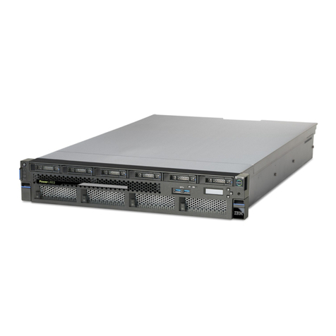
2216 Nways Multiaccess Connector
Hardware Installation Guide
GA27-4106-00


ÉÂÔ 2216 Nways Multiaccess Connector
Hardware Installation Guide
GA27-4106-00

Note
Before using this information and the product it supports, be sure to read the general information under
Appendix A, “Notices” on page 11.
First Edition (March 1997)
This edition applies to the IBM 2216 Nways Multiaccess Connector Model 400.
Order publications through your IBM representative or the IBM branch office serving your locality. Publications are not stocked at the
address given below.
A form for readers’ comments appears at the back of this publication. If the form has been removed, address your comments to:
Department CGF
Design & Information Development
IBM Corporation
PO Box 12195
RESEARCH TRIANGLE PARK NC 27709-9990
USA
When you send information to IBM, you grant IBM a nonexclusive right to use or distribute the information in any way it believes
appropriate without incurring any obligation to you.
Copyright International Business Machines Corporation 1997. All rights reserved.
Note to U.S. Government Users — Documentation related to restricted rights — Use, duplication or disclosure is subject to
restrictions set forth in GSA ADP Schedule Contract with IBM Corp.

About This Guide
This guide explains how to set up the IBM 2216, and how to identify and correct
some problems that occur during setup.
Who Should Use This Guide
This guide is intended for the person responsible for installing the IBM 2216. This
person should be familiar with installation and cabling charts.
About the Illustrations
The illustrations in this guide represent one possible configuration for the IBM 2216.
The illustrations assume that the redundant power supply is installed and almost all
of the slots are filled.
Copyright IBM Corp. 1997 iii

iv 2216 Hardware Installation Guide

Setting Up the IBM 2216
These instructions explain how to rack-mount and surface-mount the IBM 2216.
1 Unpack and Verify
Unpack the IBM 2216 and verify that, along
with this guide, the following items were
included:
Documentation
¹
Caution: Safety Information–Read This
First
, SD21-0030
¹
IBM 2216 Planning Guide
, GA27-4105
¹
IBM 2216 Maintenance Guide
, SY27-0350
¹
Hardware Configuration Quick Reference
Card
, GX27-3988
Hardware
¹Any cables ordered
¹Rack Mount Installation aid
¹Power cord for each power supply
¹PCMCIA Modem (except in countries
where the PCMCIA modem is not
available)
Rack-mounting- proceed with step 2a.
Surfacing-mounting - proceed with step
2b on page 2.
2a Rack-Mounting the Model 200
You need the following items:
¹Cables, as required
¹Eight rack-mounting screws
¹Screwdriver
Notes:
1. You will need a second person to help hold
the IBM 2216 while it is being mounted.
2. If you have a shelf for the rack, install it
before continuing.
3. Do not use the installation aid if you have a
shelf installed.
Continue with step 3 on page 2.
1

2b Surface-Mounting the Model 200
You need the following items:
¹Cables, as required
Continue with step 9 on page 4.
3 (Rack-Mounting)
To make the IBM 2216 easier to lift, remove:
1. The Fan tray
2. Each power supply.
To remove them, loosen the screws on each
component and pull the handles.
22216 Hardware Installation Guide

4 (Rack-Mounting)
REAR
The mounting brackets are shipped with the
flanges facing the rear:
1. Remove the two screws at the top and
bottom of each bracket
2. Reverse each bracket so that the IBM 2216
can be rack-mounted
3. Reinstall the four screws.
When the brackets are fitted correctly, the letter
embossed on each bracket is in the top-rear
corner; an A on the right side and a B on the
left side.
5 (Rack-Mounting)
The installation aid is a metal bar that supports
the IBM 2216 as you install it in the rack. The
installation aid ensures that the IBM 2216 and
rack are lined up correctly.
Line up the holes in the installation aid with the
rack and install all screws.
3

6 (Rack-Mounting)
With the second person’s help, set the IBM
2216 on the IBM 2216 installation aid or on the
shelf. The mounting brackets keep the IBM
2216 from falling into the rack during
installation.
With the installation aid installed, one person
can steady the IBM 2216 while completing the
next step.
7 (Rack-Mounting)
1
3
2
4
Install the pairs of screws in the order shown.
8 (Rack-Mounting)
Reinstall the fan tray and each power supply,
making sure the screws are secured.
If the power supply resists, shift it to the left. If
the fan tray resists, gently rock it.
9 (Rack- or Surface-Mounting)
If you are installing a PCMCIA modem, slide it
into the port of the system card. Attach the
telephone cable to the modem (a triangle
identifies the top of the cable).
42216 Hardware Installation Guide

10 (Rack- or Surface-Mounting)
✹✹
✹
✹
✹
✹
✹
✹
✹
✹
AB 1
5
2
6
3
7
4
8
1. Connect the power cords to the IBM 2216
and the power outlets. Switch on each
power supply. After 5 minutes, verify that
the correct LEDs are on. (See “LED
Status” on page 9.)
2. Ensure that the
Hardware Configuration
Quick Reference
card is completed and
placed in the area provided under the IBM
2216 on the left.
11 Complete the Setup (Rack or Surface)
1. Connect the cables.
2. Label the IBM 2216 with its unique unit
number or name on the top right of the
front panel.
3. Report the phone number of the modem to
the network administrator and return all the
charts. The IBM 2216 is ready to be
configured.
5

62216 Hardware Installation Guide

Problem Solving
To identify and correct any problems that occur during setup, answer the questions (Qs) and take the
appropriate actions, as indicated:
Q: On the power supply, is the AC OK LED
off?
Yes: There is no AC source voltage.
1. Switch each power supply off.
2. Check the power source.
3. Ensure that the power cord is attached
correctly.
4. Switch each power supply on.
If the problem is not corrected, contact your
service representative.
No: Go to the next question.
Q: On the power supply, is the DC OK LED
off?
Yes: There is no +5V, +12V, or -48V dc
output voltage.
1. Switch each power supply off.
2. Reseat the power supply, ensuring that
the power cord is attached correctly, and
switch each power supply on.
If the problem is not corrected, contact your
service representative.
No: Go to the next question.
Q: On the power supply, is the Overcurrent
LED on?
Yes: There is an overcurrent condition in an
adapter or in the fan tray.
1. Remove the adapter that has its top
yellow LED on. If none is on, remove the
fan tray.
2. Press the Overcurrent Reset button.
If the problem is not corrected, contact your
service representative.
No: Go to the next question.
Q: On the system card, is the top yellow LED
on?
Yes: There is a fault in the card.
1. Switch off each power supply.
2. Reseat the card.
3. Switch on each power supply.
If the problem is not corrected, contact your
service representative.
No: Go to the next question.
Q: On the system card, is the top green LED
off?
Yes: The green LED is switched on by the
operational code.
If the green LED fails to come on, contact
your service representative.
No: Go to the next question.
Q: On the system card, is the PCMCIA port
LED on?
Yes: Either the PCMCIA card slot is empty or
the card failed the power-on self-test. Reseat
the card.
If the problem is not corrected, contact your
service representative.
No: Go to the next question.
Q: On any card (slots 1 through 8), is the top
yellow LED on?
Yes: There is a fault in the card. Reseat the
adapter.
If the problem is not corrected, contact your
service representative.
No: Go to the next question.
Q: On any card (slots 1 through 8), is the
wrong slot LED on?
Yes: The adapter is in the wrong slot.
1. Find the correct slot.
2. Move the adapter to the correct slot.
If the problem is not corrected, contact your
service representative.
No: If none of the questions was answered
yes, contact your service representative.
See the
IBM 2216 Planning Guide
for a list of
restrictions regarding adapters and IBM 2216
slots.
Copyright IBM Corp. 1997 7

82216 Hardware Installation Guide

Adapter Placement
Write in the feature codes of each of your
adapters on the diagram below
.
┌─────────────────────────────────────────────────────────┐
│ Adapter Slots │
├───────────────┬──────┬──────┬──────┬──────┬──────┬──────┤
│ │A │B │1 │2 │3 │4 │
│ │ │ │ │ │ │ │
│ │ │ │ │oo│ │ │
│ │ │ │ │ │ │ │
│ │ │ │ │o│ │ │
│ │ │ │ │ │ │ │
│ │ │ │ │oo│ │ │
│Redundant │ │ │ │ │ │ │
│ Power │ │ │ │ o o │ │ │
│ Supply │ │ │ │ │ │ │
│ │ │ │ │ │ │ │
│ │ │ │ │ │ │ │
│ │ │1 2 │ │ │ │ │
│ │ │o o │ │ │ │ │
│ │ │ │ │ │ │ │
│ │ │o o │ │ │ │ │
│ │ │ │ │ │ │ │
├───────────────┤ │o ├──────┼──────┼──────┼──────┤
│ o │ │ │ │ │ │ │
│ │ │o│ │ │ │ │
│ o │ │ │ │ │ │ │
│ │ │ │ │ │ │ │
│ │ │S│ │ │ │ │
│ │ │y│ │ │ │ │
│ o (AC) │ │ s │││││
│ │ │t│ │ │ │ │
│ o (DC) │ │ e │││││
│ │ │m│ │ │ │ │
│ │ │ │ │ │ │ │
│ │ │C│ │ │ │ │
│ │ │a│ │ │ │ │
│Power │ │ r │ │ │ │ │
│ Supply │ │ d │ │ │ │ │
│ │ │ │ │ │ │ │
│ │ │ │5│6│7│8│
├───────────────┴──────┴──────┴──────┴──────┴──────┴──────┤
│ │
│ Fan Tray │
│ │
└─────────────────────────────────────────────────────────┘
Power Supply Status
LED Status
Important Names and Numbers
System Card LEDs Meaning
PCMCIA 1 or
PCMCIA 2
(Yellow) On
PCMCIA device has a fault,
is not installed, or is not
seated correctly.
OK (Green) On Card hardware is operating
normally.
FAULT (Yellow) On Card hardware has a fault.
Hard Drive (Yellow)
On Hard drive has failed.
Adapter LEDs Meaning
OK (Green) On Adapter is operating
normally.
FAULT (Yellow) On Adapter has a fault.
Wrong slot (Yellow) Adapter is in the wrong slot.
Green port
When on
When off
Port is operating normally.
Port is not configured or is
disabled.
Yellow port
When on
When flashing
One or more ports has a
hardware fault.
One or more ports has a
port I/O or network failure
(use external wrap plug to
isolate).
Contact Name Telephone
Number
System Administrator
LEDs Meaning
Yellow On
(Overcurrent) There is an overcurrent condition
caused by an adapter or fan
assembly.
Service Representative
Green DC On +5 V, +12 V, and −48 V are OK.
Green AC On AC voltage is present.
9

10 2216 Hardware Installation Guide

Appendix A. Notices
References in this publication to IBM products, programs, or services do not imply
that IBM intends to make these available in all countries in which IBM operates.
Any reference to an IBM product, program, or service is not intended to state or
imply that only IBM’s product, program, or service may be used. Subject to IBM’s
valid intellectual property, or other legally protectable rights, any functionally
equivalent product, program, or service that does not infringe any of IBM’s
intellectual property rights may be used instead of the IBM product, program, or
service. The evaluation and verification of operation in conjunction with other
products, except those expressly designated by IBM, are the user’s responsibility.
IBM may have patents or pending patent applications covering subject matter in
this document. The furnishing of this document does not give you any license to
these patents. You can send license inquiries, in writing, to:
IBM Director of Licensing
IBM Corporation
500 Columbus Avenue
Thornwood, NY 10594 USA
Electronic Emission Notices
Federal Communications Commission (FCC) Statement
Note: This equipment has been tested and found to comply with the limits for a
Class A digital device, pursuant to Part 15 of the FCC Rules. These limits are
designed to provide reasonable protection against harmful interference when the
equipment is operated in a commercial environment. This equipment generates,
uses, and can radiate radio frequency energy and, if not installed and used in
accordance with the instruction manual, may cause harmful interference to radio
communications. Operation of this equipment in a residential area is likely to cause
harmful interference, in which case the user will be required to correct the
interference at his own expense.
Properly shielded and grounded cables and connectors must be used in order to
meet FCC emission limits. IBM is not responsible for any radio or television
interference caused by using other than recommended cables and connectors or by
unauthorized changes or modifications to this equipment. Unauthorized changes or
modifications could void the user's authority to operate the equipment.
This device complies with Part 15 of the FCC Rules. Operation is subject to the
following two conditions: (1) this device may not cause harmful interference, and
(2) this device must accept any interference received, including interference that
may cause undesired operation.
Copyright IBM Corp. 1997 11

FCC Part 68 Compliance Information:
Features and optional adapters for the IBM 2216 comply with Part 68 of the FCC
rules. The label included on the adapter tray contains, among other information,
the FCC registration number and Ringer Equivalence Number (REN), if applicable
for this equipment. If requested, provide this information to your telephone
company.
The features and adapters included are:
Feature Code Part Name
2283 1-Port ISDN PRI (T1/J1) Adapter LIC 283 with interface code
04DU9-1SN, service code 6.0N and jack type RJ48C.
The REN is useful to determine the quantity of devices you may connect to your
telephone line and still have those devices ring when your number is called. In
most, but not all areas, the sum of the RENs of all devices should not exceed five
(5.0). To be certain of the number of devices you may connect to your line, as
determined by the REN, you should call your local telephone company to determine
the maximum REN for your calling area.
If the IBM 2216 causes harm to the telephone network, the Telephone Company
may discontinue your service temporarily. If possible, they will notify you in
advance. But if advance notice isn’t practical, you will be notified as soon as
possible. You will be advised of your right to file a complaint with the FCC.
Your telephone company may make changes in its facilities, equipment, operations,
or procedures that could affect the proper operation of your equipment. If they do,
you will be given advance notice so as to give you an opportunity to maintain
uninterrupted service.
If trouble is experienced with this equipment, for repair or warranty information, in
the United States, call IBM at 1-800-IBM-SERV. In Canada, call IBM at
1-800-465-6600.
No repairs can be performed by the customer.
Industry Canada Compliance Statement
This digital apparatus does not exceed the Class A limits for radio noise emissions
from digital apparatus as set out in the interference-causing equipment standard
entitled:
Digital Apparatus
, ICES-003 of Industry Canada.
Avis de conformité aux normes d'Industrie Canada
Cet appareil numérique respecte les limites de bruits radioélectriques applicables
aux appareils numériques de Classe A prescrites dans la norme sur le matériel
brouiller:
Appareils numériques
, NMB-003 édictée par Industrie Canada.
Industry Canada Information:
NOTICE: The Industry Canada label identifies certified equipment. This certification
means that the equipment meets certain telecommunications network protective,
12 2216 Hardware Installation Guide

operational and safety requirements. Industry Canada does not guarantee the
equipment will operate to the user’s satisfaction.
Before installing this equipment, users should ensure that it is permissible to be
connected to the facilities of the local telecommunications company. The
equipment must also be installed using an acceptable method of connection. In
some cases, the company’s inside wiring associated with a single line individual
service may be extended by means of a certified connector assembly (telephone
extension cord). The customer should be aware that compliance with the above
conditions may not prevent degradation of service in some situations.
Repairs to certified equipment should be made by an authorized Canadian
maintenance facility designated by the supplier. Any repairs or alterations made by
the user to this equipment, or equipment malfunctions, may give the
telecommunications company cause to request the user to disconnect the
equipment.
Users should ensure for their own protection that the electrical ground connections
of the power utility, telephone lines and internal metallic water pipe system, if
present, are connected together. This precaution may be particularly important in
rural areas.
CAUTION: Users should not attempt to make such connections themselves, but
should contact the appropriate electrical inspection authority, or electrician, as
appropriate.
AVIS : L’étiquette d’Industrie Canada permet d’identifier un équipement
homologué. Cette homologation signifie que cet équipement satisfait certaines
exigences en matière de protection, d’exploitation et de sécurité du réseau de
télécommunications. Industrie Canada n’offre aucune garantie que le
fonctionnement de cet équipement soit à la satisfaction de l’utilisateur.
Avant d’installer cet équipement, l’utilisateur doit s’assurer qu’il a la permission de
le raccorder aux installations de l’entreprise de télécommunications. L’installation
de cet équipement doit aussi se faire selon un mode de raccordement acceptable.
Dans certains cas, le câblage interne de l’entreprise associé au service individuel
offert par une ligne d’abonné peut être prolongé au moyen d’un connecteur
homologué (prolongateur de téléphone). Le client devrait être informé que la
conformité de son équipement aux conditions susmentionnées n’est pas une
prévention contre la dégradation du service dans certaines situations.
Toute réparation d’un équipement homologué devrait être effectuée par un service
de maintenance canadien autorisé qui a été désigné par le fournisseur. Toute
réparation ou modification d’équipement faite par l’utilisateur, ou tout mauvais
fonctionnement, pourrait entraîner la déconnexion de cet équipement par
l’utilisateur à la demande de l’entreprise de télécommunications.
Pour sa protection personnelle, l’utilisateur devrait s’assurer que les mises à la
terre des services publics électriques, des lignes téléphoniques et du système
interne des canalisations d’eau à tuyaux métalliques, advenant leur présence, sont
interconnectées. Dans les zones rurales, il s’agit-là d’une précaution
particulièrement importante à prendre.
Appendix A. Notices 13

ATTENTION : Toute tentative de connexion par l’utilisateur est à déconseiller. Il
est préférable de communiquer avec le responsable de l’inspection en électricité ou
un électricien, selon le cas.
European Community (EC) Mark of Conformity Statement
This product is in conformity with the protection requirements of EC Council
Directive 89/336/EEC on the approximation of the laws of the Member States
relating to electromagnetic compatibility. IBM cannot accept responsibility for any
failure to satisfy the protection requirements resulting from a non-recommended
modification of the product, including the fitting of non-IBM option cards.
A typical host which conforms to the protection requirements of EC Council
Directive 89/336/EEC on the approximation of the law of the Member States
relating to electromagnetic compatibility will continue to conform when this product
is installed and operated in it.
Operation of this product in a domestic/residential environment may cause radio
interference, which the user may be required to take measures to suppress.
A Declaration of Conformity with the requirements of the Directive has been signed
by IBM Spain, Division of Fabricacion, 46185 La Pobla de Vallbona, Valencia,
Spain.
The product bears the Telecom CE mark (CE 168 X) for ISDN Basic Rate
complying with I-CTR3 (Bridging measures) as per the European directive
91/263/EEC (TTE directive). The product bears the Telecom CE mark (CE 168 X)
for: V.24/V.28,V36 and X.21 electrical interfaces complying with NET 1 and with
NET 2 physical level. ISDN Basic Rate complying with I-CTR3 (Bridging measures)
as per the European directive 91/263/EEC (TTE directive).
This product has been tested and found to comply with the limits for Class B
Information Technology Equipment according to CISPR 22 / European Standard EN
55022. The limits for Class B equipment were derived for typical residential
environments to provide reasonable protection against interference with licensed
communication devices.
Dieses Gerät ist berechtigt in Übereinstimmung mit dem deutschen EMVG vom
9.Nov.92 das EG-Konformitätszeichen zu führen. Der Außteller der
Konformitätserklärung ist die IBM Spain, Division of Fabricacion, 46185 La Pobla
de Vallbona, Valencia, Spain.
Dieses Gerät erfüllt die Bedingungen der EN 55022 Klasse B.
Japanese Voluntary Control Council for Interference (VCCI) Statement
This equipment is Class 1 Equipment (information equipment to be used in
commercial and industrial districts) which is in conformance with the standard set
by the Voluntary Control for Interference Council by Data Processing Equipment
and Electronic Office Machines (VCCI) with an aim to prevent radio interference in
commercial and industrial districts. This equipment could cause interference to
radio and television receivers when used in and around residential districts. Please
handle the equipment properly according to the instruction manual.
14 2216 Hardware Installation Guide
Other IBM Cables And Connectors manuals
Popular Cables And Connectors manuals by other brands

BrassCraft
BrassCraft Safety+PLUS ADVANTAGE Installation instructions manual
HP
HP A3352A - 4 GB Hard Drive installation guide
Philips
Philips Sonicare 300 SerieS user manual
CommScope
CommScope BUDI-S installation instructions

Sensio
Sensio Gamma SE988950 quick start guide

Emtron
Emtron KV Series Hardware manual
Staubli
Staubli ID/S10BV-C Series Assembly instructions

CommScope
CommScope SYSTIMAX VisiPatch CPC5562 instruction sheet

CYP
CYP CLUX-12E Operation manual

Painless Performance Products
Painless Performance Products 60103 quick start guide
Cypress
Cypress CLUX-14CEC Operation manual

Chicago Electric
Chicago Electric 93633 operating instructions
