IBM RPQ 7L1184 Setup guide

3745 Communication Controller
Models 130, 150, 160, 170, and 17A
3746 Expansion Unit Model 900 IBM
100/120-Volt Connection RPQ 7L1184
Installation and Maintenance Information
SY33-2078-3


3745 Communication Controller
Models 130, 150, 160, 170, and 17A
3746 Expansion Unit Model 900 IBM
100/120-Volt Connection RPQ 7L1184
Installation and Maintenance Information
SY33-2078-3

Note!
Before using this information and the product it supports, be sure to read the general information under “Notices”
on page v.
Fourth Edition (January 1995)
The information contained in this manual is subject to change from time to time. Any such changes will be reported in subsequent
revisions. Changes have been made throughout this edition, and this manual should be read in its entirety.
Order publications through your IBM representative or the IBM branch office serving your locality. Publications are not stocked at the
addresses given below.
A form for readers' comments appears at the back of this publication. If the form has been removed, address your comments to:
International Business Machines Corporation
Department 6R1LG
180 Kost Road
Mechanicsburg PA 17055-0180
U.S.A.
or
IBM France
Centre d'Etudes et Recherches
Service 0762 BP 79
06610 La Gaude
France
When you send information to IBM, you grant IBM a non-exclusive right to use or distribute the information in any way it believes
appropriate without incurring any obligation to you.
Copyright International Business Machines Corporation 1989, 1995. All rights reserved.
Note to U.S. Government Users — Documentation related to restricted rights — Use, duplication or disclosure is subject to
restrictions set forth in GSA ADP Schedule Contract with IBM Corp.

Contents
Notices . . . . . . . . . . . . . . . . . . . . . . . . . . . . . . . . . . . . . . . . . . v
Electronic Emission Notices ............................... v
Safety . . . . . . . . . . . . . . . . . . . . . . . . . . . . . . . . . . . . . . . . . . vii
General Safety . . . . . . . . . . . . . . . . . . . . . . . . . . . . . . . . . . . . . vii
Service Inspection Procedure ............................. vii
Procedure Steps . . . . . . . . . . . . . . . . . . . . . . . . . . . . . . . . . . . vii
Chapter 1. Generalities . . . . . . . . . . . . . . . . . . . . . . . . . . . . . . . 1-1
Introduction . . . . . . . . . . . . . . . . . . . . . . . . . . . . . . . . . . . . . . . 1-1
Specifications . . . . . . . . . . . . . . . . . . . . . . . . . . . . . . . . . . . . . . 1-2
Dimensions . . . . . . . . . . . . . . . . . . . . . . . . . . . . . . . . . . . . . . 1-2
Service Clearances . . . . . . . . . . . . . . . . . . . . . . . . . . . . . . . . . 1-2
Weight . . . . . . . . . . . . . . . . . . . . . . . . . . . . . . . . . . . . . . . . 1-2
Heat Output . . . . . . . . . . . . . . . . . . . . . . . . . . . . . . . . . . . . . 1-2
Airflow . . . . . . . . . . . . . . . . . . . . . . . . . . . . . . . . . . . . . . . . . 1-2
Power Requirements . . . . . . . . . . . . . . . . . . . . . . . . . . . . . . . . 1-2
Environment, Operating . . . . . . . . . . . . . . . . . . . . . . . . . . . . . . 1-2
Plan View . . . . . . . . . . . . . . . . . . . . . . . . . . . . . . . . . . . . . . . . 1-3
Component Location . . . . . . . . . . . . . . . . . . . . . . . . . . . . . . . . . . 1-4
Installation . . . . . . . . . . . . . . . . . . . . . . . . . . . . . . . . . . . . . . . . 1-5
Operation . . . . . . . . . . . . . . . . . . . . . . . . . . . . . . . . . . . . . . . . 1-6
Maintenance . . . . . . . . . . . . . . . . . . . . . . . . . . . . . . . . . . . . . . 1-7
AC Voltage Limits .................................. 1-7
Transformer Assembly Part Number ......................... 1-8
Power Attachment Cord Assemblies ....................... 1-8
Copyright IBM Corp. 1989, 1995 iii

iv RPQ 7L1184

Notices
References in this publication to IBM products, programs or services do not imply
that IBM intends to make these available in all countries in which IBM operates.
Any reference to an IBM product, program, or service is not intended to state or
imply that only IBM's product, program, or service may be used. Any functionally
equivalent product, program, or service that does not infringe any of IBM's intellec-
tual property rights may be used instead of the IBM product, program, or service.
Evaluation and verification of operation in conjunction with other products, except
those expressly designated by IBM, is the user's responsibility.
IBM may have patents or pending patent applications covering subject matter in
this document. The furnishing of this document does not give you any license to
these patents. You can send license inquiries, in writing, to the IBM Director of
Commercial Relations, IBM Corporation, Purchase, NY 10577, U.S.A.
Electronic Emission Notices
Federal Communications Commission (FCC) Statement
Note: This equipment has been tested and found to comply with the limits for a
Class A digital device, pursuant to Part 15 of the FCC Rules. These limits are
designed to provide reasonable protection against harmful interference when the
equipment is operated in a commercial environment. This equipment generates,
uses, and can radiate radio frequency energy and, if not installed and used in
accordance with the instruction manual, may cause harmful interference to radio
communications. Operation of this equipment in a residential area is likely to cause
harmful interference, in which case the user will be required to correct the interfer-
ence at his own expense.
Properly shielded and grounded cables and connectors must be used in order to
meet FCC emission limits. IBM is not responsible for any radio or television inter-
ference caused by using other than recommended cables and connectors or by
unauthorized changes or modifications to this equipment. Unauthorized changes or
modifications could void the user's authority to operate the equipment.
This device complies with Part 15 of the FCC Rules. Operation is subject to the
following two conditions: (1) this device may not cause harmful interference, and
(2) this device must accept any interference received, including interference that
may cause undesired operation.
For Canada,
Canadian Department of Communication Statement,
GX27-3883,
applies.
Copyright IBM Corp. 1989, 1995 v

vi RPQ 7L1184

Safety
General Safety This product meets IBM safety standards.
For general safety information, see:
IBM Telecommunication Products Safety
Handbook
, GA33-0126.
Service Inspection Procedure
The following procedure helps the service representative check that the transformer
assembly conforms with IBM safety criteria. It is to be used whenever safety is
suspected.
Any deficiencies detected when using this procedure (if they make the transformer
unsafe) must be, either reported to the owner and/or user, or corrected by
exchanging the transformer assembly.
The areas checked by this procedure are:
1. Input power voltage
2. Circuit protector
3. Safety label
4. Power supply part number
5. Grounding
6. Covers.
Important Note
The transformer assembly is a sealed unit. It cannot be opened for mainte-
nance.
Procedure Steps
Step 1
Input power voltage
– Check that the voltage indicated on the transformer assembly power rating
plate is consistent with the voltage level measured at the customer's power
receptacle. See Figure 1-2 on page 1-4 for location.
Step 2
Circuit protector
– Check that the circuit protector is not damaged and physically operates cor-
rectly.
Step 3
Safety label
– Check that the safety labels are present. See Figure 1-2 on page 1-4 for
location.
Copyright IBM Corp. 1989, 1995 vii

Step 4
Power supply part number
– Check that the part number written on the transformer assembly is con-
sistent with “Transformer Assembly Part Number” on page 1-8
Step 5
Grounding
– Check that electrical continuity is assured between the ground wires of the
power cords and between those ground wires and the frame ground.
Step 6
Cover
– The transformer assembly is a sealed unit. Check that the rivets are in
place and have not been forced.
viii RPQ 7L1184

Chapter 1. Generalities
Introduction This RPQ allows connecting an IBM 3745 Communication Controller Model 130,
150, 160, 170 or 17A or an IBM 3746 Expansion Unit Model 900 to a customer's
100/120-volt power supply.
It consists of a transformer with an input power cord with a plug and an output
power cord. Overload protection is provided through a circuit protector at the input.
The transformer assembly is a sealed unit. It cannot be opened for maintenance.
Copyright IBM Corp. 1989, 1995 1-1

Specifications
Dimensions Front Side Height
mm 170 220 160
(inches) (6.69) (8.66) (6.30)
Service Clearances Front Rear Right Left
mm 250 none 25 25
(inches) (9.84) (0.98) (0.98)
See Figure 1-1 on page 1-3.
Weight 17 kg (37.25 lb)
Heat Output 50 W
Airflow Convection only
Power Requirements
kVA 1.2
Phase 1
Input Current 11 A maximum for United States/Canada
13 A maximum for Japan
Inrush current 180 A maximum
Branch circuit ampacity 15 A
Voltage 60 Hz 120 V for United States/Canada
50/60 Hz 100 V for Japan
Frequency 50/60 Hz
Environment, Operating
Temperature 10°C-41°C (50°F-105°F)
Relative Humidity 8% to 80%
1-2 RPQ 7L1184

Plan View Metric scale: 1 mm = 5 mm. Measurements in inches are shown in parentheses.
(1) A floor cutout is required for raised floor installation.
Figure 1-1. Plan View
Chapter 1. Generalities 1-3
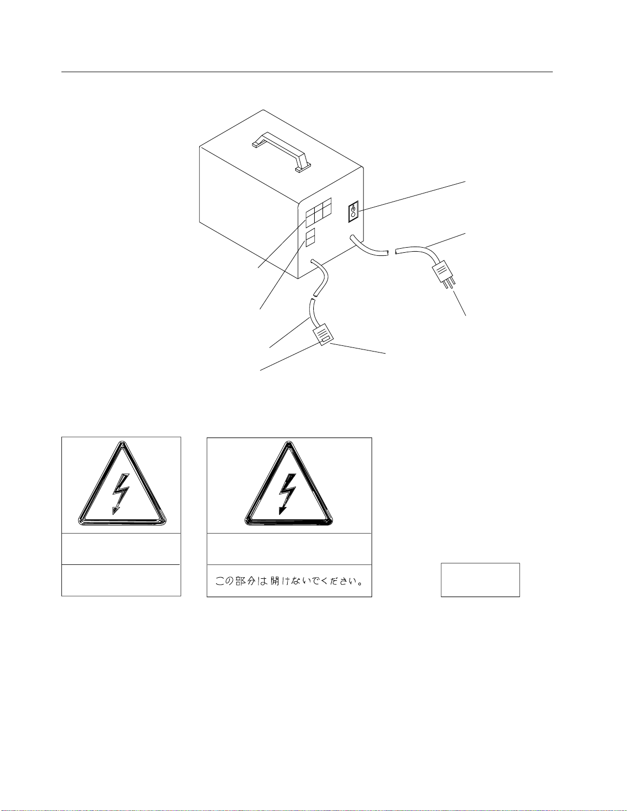
Component Location
Circuit Protector
Input cord (2)
National Plug (2)
Power Rating
Plate
Safety Label
(See Detail B)
NE PAS OUVRIR
DO NOT OPEN
240 V
Detail B
Output Cord (2) IEC Plug
DO NOT OPEN
Safety label
(See Detail C)
U.S.A and CANADA
Detail C
JAPAN
(2) For details on cord length and plug type, see
“Transformer Assembly Part Number” on page 1-8.
Figure 1-2. Component Location
1-4 RPQ 7L1184

Installation 1. Measure the customer's primary power using the
3745-130/150/160/170/17A
and 3746-900 Installation Guide
, SY33-2067, Chapter 2 "Measuring the Cus-
tomer's Primary Power", steps 1 through 3.
The acceptable voltage limits are: 90 through 127 volts. See “Input Voltages”
on page 1-7.
2. Ensure that the 3745 is not connected to the customer's power supply
Ensure that CB1 is switched to OFF on the front of the 3745 primary power box
(see Figure 1-3 for location).
Voltage
Selection
Switch
220
200
240
J6 J7
J9
J8
F1
SW1
Main Line CB
CB1 CP2
CP3
J1
Figure 1-3. Primary Power Box (Front View)
On the front side of the primary power box, set the SW1 switch (see Figure 1-3
for location) to position 240.
3. If the machine is shipped with the 200/240-volts line cord installed, it must be
disconnected and removed.
a. Remove the clamp securing the power cord. Keep this clamp and its screw
for further use.
b. Disconnect the power cord from connector J3 (see Figure 1-4 on page 1-6
for location).
Chapter 1. Generalities 1-5

EPO Connectors
J5 J6 J7 J8
J3
J2
Frame
Ground
Main Line
Customer
Power
Control
Figure 1-4. Primary Power Box (Rear View)
4. Place the transformer assembly according to “Service Clearances” on
page 1-2. The transformer must be installed above the raised floor (if present).
IMPORTANT
Ensure that the transformer is placed so that it will not cause a tripping
hazard. Place it against a wall, on or under a desk or table, away from
aisles.
5. Plug the output power cord of the transformer to connector J3. Secure the
cable with the clamp and screw removed in step 3a.
6. Route the input power cord to the customer's receptacle, and insert the power
plug into the customer's main socket.
7. Switch the transformer assembly circuit protector to the ON position.
8. Continue the 3745 installation using the
Installation Guide
Chapter 2, step 4 of
"3745 Connection to Customer's Primary Power".
Operation The transformer is a passive device requiring no action. The 3745 power
(ON/OFF) will still be controlled by the 3745 control panel. The circuit protector on
the transformer is for circuit protection only and should not be used as an ON/OFF
switch.
1-6 RPQ 7L1184

Maintenance In case of problems, the transformer assembly being a FRU, the entire assembly
must be exchanged. Before the exchange, check if the circuit protector is in the
ON position.
For part number assembly refer to “Transformer Assembly Part Number” on
page 1-8.
AC Voltage Limits
Input Voltages
┌──────────┬─────────┬────────┐
│ Voltages │ Canada │ Japan │
│ │ U.S.A │ │
├──────────┼─────────┼────────┤
│ Nominal │ 12ð │ 1ðð │
├──────────┼─────────┼────────┤
│ Minimum │ 114 │ 9ð │
├──────────┼─────────┼────────┤
│ Maximum │ 127 │ 11ð │
└──────────┴─────────┴────────┘
Output Voltages
┌───────────────────┐
│ Voltages │
├───────────────────┤
│ Nominal 24ð │
├───────────────────┤
│ Minimum 21ð │
├───────────────────┤
│ Maximum 26ð │
└───────────────────┘
Chapter 1. Generalities 1-7

Transformer Assembly Part Number
┌────────────────────────────────────────┬─────────┬───────┬────────────────┐
│ Country │ P/N │ Plugñ │ Cord Lengthò│
│ │ │ │ Input │ Output │
├────────────────────────────────────────┼─────────┼───────┼───────┼────────┤
│ Chicago locking plug │ 34F1229 │ 7 │ ð.46 │ 1.22 │
│ │ │ │ (18) │ (48) │
│ Chicago non-locking plug │ 34F123ð │ 4 │ ð.46 │ 1.22 │
│ │ │ │ (18) │ (48) │
│ Chicago moisture resistant plug │ 34F1231 │ 51 │ ð.46 │ 1.22 │
│ │ │ │ (18) │ (48) │
│ U.S.A, CANADA locking plug │ 34F1232 │ 7 │ ð.46 │ 3.57 │
│ │ │ │ (18) │ (14ð) │
│ U.S.A, CANADA non-locking plug │ 34F1233 │ 4 │ ð.46 │ 3.57 │
│ │ │ │ (18) │ (14ð) │
│ U.S.A, CANADA moisture resistant plug │ 34F1234 │ 51 │ ð.46 │ 3.57 │
│ │ │ │ (18) │ (14ð) │
│ JAPAN locking plug │ 34F1235 │ 2ð │ 1.3ð │ 2.72 │
│ │ │ │ (51) │ (1ð6) │
│ JAPAN non-locking plug │ 34F1293 │ 4 │ 1.3ð │ 2.72 │
│ │ │ │ (51) │ (1ð6) │
└────────────────────────────────────────┴─────────┴───────┴───────┴────────┘
ñ See “Power Attachment Cord Assemblies.”
ò Metric measurements (meters), English measurements are shown in
parentheses (inches).
Power Attachment Cord Assemblies
1 2 5 V
1 5 A
1 2 5 V
1 5 A
2 0 A
1 2 5 V
1 2 5 V
1 5 A
1-8 RPQ 7L1184

Readers' Comments — We'd Like to Hear from You
3745 Communication Controller
Models 130, 150, 160, 170, and 17A
3746 Expansion Unit Model 900
100/120-Volt Connection RPQ 7L1184
Installation and Maintenance Information
Publication No. SY33-2078-3
Please send us your comments concerning this book. We will greatly appreciate them and will consider
them for later releases of the present book.
If you prefer sending comments by FAX or electronically, use:
FAX: 33 4 93 24 77 97
IBM Internal Use: LGERCF at IBMFR
Internet: [email protected]
In advance, thank you.
Your comments:
Name Address
Company or Organization
Phone No.

Cut or Fold
Along Line
Cut or Fold
Along Line
Readers' Comments — We'd Like to Hear from You
SY33-2078-3 IBM
Fold and Tape Please do not staple Fold and Tape
PLACE
POSTAGE
STAMP
HERE
IBM France
Centre d'Etudes et Recherches
Service 0798 - BP 79
06610 La Gaude
France
Fold and Tape Please do not staple Fold and Tape
SY33-2078-3
Other IBM Cables And Connectors manuals


