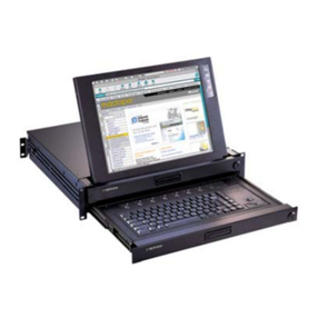
IBM T-117 Instruction Manual

IBM
17 ″
1
U
Flat
Panel
Monitor
Console
Kit
Installation
and
Maintenance
Guide


IBM
17 ″
1
U
Flat
Panel
Monitor
Console
Kit
Installation
and
Maintenance
Guide

Note:
Before
using
this
information
and
the
product
it
supports,
read
the
general
information
in
Appendix
B,
“IBM
Statement
of
Limited
Warranty
Z125-4753-07
11/2002,”
on
page
29
and
the
notices
information
in
Appendix
C,
“Notices,”
on
page
47.
First
Edition
(March
2004)
©
Copyright
International
Business
Machines
Corporation
2004.
All
rights
reserved.
US
Government
Users
Restricted
Rights
–
Use,
duplication
or
disclosure
restricted
by
GSA
ADP
Schedule
Contract
with
IBM
Corp.

Contents
Safety
.
.
.
.
.
.
.
.
.
.
.
.
.
.
.v
Chapter
1.
Introduction
.
.
.
.
.
.
.
.1
Inventory
checklist
.
.
.
.
.
.
.
.
.
.
.
.1
Notices
and
statements
used
in
this
document
.
.
.3
Chapter
2.
Installing
the
Flat
Panel
Monitor
Console
Kit
.
.
.
.
.
.
.
.
.5
Installing
the
flat-panel
monitor
and
keyboard
tray
.5
Installing
an
optional
console
switch
.
.
.
.
.
.14
Chapter
3.
Hardware
maintenance
information
.
.
.
.
.
.
.
.
.
.
.
.
.17
Customer-replaceable
unit
part
numbers
.
.
.
.
.17
Replacing
the
cable-management
arm
.
.
.
.
.19
Replacing
the
slide-rail
assemblies
.
.
.
.
.
.
.21
Replacing
the
keyboard
.
.
.
.
.
.
.
.
.
.25
Appendix
A.
Getting
help
and
technical
assistance
.
.
.
.
.
.
.
.
.
.
.
.
.27
Before
you
call
.
.
.
.
.
.
.
.
.
.
.
.
.27
Using
the
documentation
.
.
.
.
.
.
.
.
.
.27
Getting
help
and
information
from
the
World
Wide
Web
.
.
.
.
.
.
.
.
.
.
.
.
.
.
.
.
.27
Software
service
and
support
.
.
.
.
.
.
.
.28
Hardware
service
and
support
.
.
.
.
.
.
.
.28
Appendix
B.
IBM
Statement
of
Limited
Warranty
Z125-4753-07
11/2002
.
.
.
.29
Part
1
-
General
Terms
.
.
.
.
.
.
.
.
.
.
.29
Part
2
-
Country-unique
Terms
.
.
.
.
.
.
.
.32
Part
3
-
Warranty
Information
.
.
.
.
.
.
.
.43
Appendix
C.
Notices
.
.
.
.
.
.
.
.
.47
Edition
notice
.
.
.
.
.
.
.
.
.
.
.
.
.47
Trademarks
.
.
.
.
.
.
.
.
.
.
.
.
.
.48
Important
notes
.
.
.
.
.
.
.
.
.
.
.
.
.48
Electronic
emission
notices
.
.
.
.
.
.
.
.
.48
Federal
Communications
Commission
(FCC)
statement
.
.
.
.
.
.
.
.
.
.
.
.
.
.48
Industry
Canada
Class
A
emission
compliance
statement
.
.
.
.
.
.
.
.
.
.
.
.
.
.49
Australia
and
New
Zealand
Class
A
statement
.49
United
Kingdom
telecommunications
safety
requirement
.
.
.
.
.
.
.
.
.
.
.
.
.49
European
Union
EMC
Directive
conformance
statement
.
.
.
.
.
.
.
.
.
.
.
.
.
.49
Taiwanese
Class
A
warning
statement
.
.
.
.50
Chinese
Class
A
warning
statement
.
.
.
.
.50
Japanese
Voluntary
Control
Council
for
Interference
(VCCI)
statement
.
.
.
.
.
.
.50
Index
.
.
.
.
.
.
.
.
.
.
.
.
.
.
.51
©
Copyright
IBM
Corp.
2004
iii

iv
IBM
17″
1
U
Flat
Panel
Monitor
Console
Kit:
Installation
and
Maintenance
Guide

Safety
Before
installing
this
product,
read
the
Safety
Information.
Antes
de
instalar
este
produto,
leia
as
Informações
de
Segurança.
Pred instalací tohoto produktu si prectete prírucku bezpecnostních instrukcí.
Læs
sikkerhedsforskrifterne,
før
du
installerer
dette
produkt.
Lees
voordat
u
dit
product
installeert
eerst
de
veiligheidsvoorschriften.
Ennen
kuin
asennat
tämän
tuotteen,
lue
turvaohjeet
kohdasta
Safety
Information.
Avant
d’installer
ce
produit,
lisez
les
consignes
de
sécurité.
Vor
der
Installation
dieses
Produkts
die
Sicherheitshinweise
lesen.
Prima
di
installare
questo
prodotto,
leggere
le
Informazioni
sulla
Sicurezza.
Les
sikkerhetsinformasjonen
(Safety
Information)
før
du
installerer
dette
produktet.
Antes
de
instalar
este
produto,
leia
as
Informações
sobre
Segurança.
©
Copyright
IBM
Corp.
2004
v

Antes
de
instalar
este
producto,
lea
la
información
de
seguridad.
Läs
säkerhetsinformationen
innan
du
installerar
den
här
produkten.
Important:
All
caution
and
danger
statements
in
this
documentation
begin
with
a
number.
This
number
is
used
to
cross
reference
an
English
caution
or
danger
statement
with
translated
versions
of
the
caution
or
danger
statement
in
the
IBM
NetBAY
Rack
Safety
Information
book.
For
example,
if
a
caution
statement
begins
with
a
number
1,
translations
for
that
caution
statement
appear
in
the
IBM
NetBAY
Rack
Safety
Information
book
under
statement
1.
Be
sure
to
read
all
caution
and
danger
statements
in
this
documentation
before
performing
the
instructions.
Read
any
additional
safety
information
that
comes
with
your
server
or
optional
device
before
you
install
the
device.
vi
IBM
17″
1
U
Flat
Panel
Monitor
Console
Kit:
Installation
and
Maintenance
Guide

Statement
4:
DANGER
Electrical
current
from
power,
telephone,
and
communication
cables
is
hazardous.
To
avoid
a
shock
hazard:
v
Do
not
connect
or
disconnect
any
cables
or
perform
installation,
maintenance,
or
reconfiguration
of
this
product
during
an
electrical
storm.
v
Connect
all
power
cords
to
a
properly
wired
and
grounded
electrical
outlet.
v
Connect
to
properly
wired
outlets
any
equipment
that
will
be
attached
to
this
product.
v
When
possible,
use
one
hand
only
to
connect
or
disconnect
signal
cables.
v
Never
turn
on
any
equipment
when
there
is
evidence
of
fire,
water,
or
structural
damage.
v
Disconnect
the
attached
power
cords,
telecommunications
systems,
networks,
and
modems
before
you
open
the
device
covers,
unless
instructed
otherwise
in
the
installation
and
configuration
procedures.
v
Connect
and
disconnect
cables
as
described
in
the
following
table
when
installing,
moving,
or
opening
covers
on
this
product
or
attached
devices.
To
Connect:
To
Disconnect:
1.
Turn
everything
OFF.
2.
First,
attach
all
cables
to
devices.
3.
Attach
signal
cables
to
connectors.
4.
Attach
power
cords
to
outlet.
5.
Turn
device
ON.
1.
Turn
everything
OFF.
2.
First,
remove
power
cords
from
outlet.
3.
Remove
signal
cables
from
connectors.
4.
Remove
all
cables
from
devices.
Safety
vii

viii
IBM
17″
1
U
Flat
Panel
Monitor
Console
Kit:
Installation
and
Maintenance
Guide

Chapter
1.
Introduction
The
IBM
®
17″
1
U
Flat
Panel
Monitor
Console
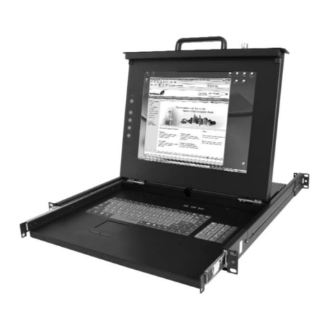
Kit
is
a
flat-panel
monitor
and
keyboard
tray
in
one
solution.
An
optional
IBM
PS/2
®
Travel
Keyboard
with
UltraNav
fits
inside
the
front
of
the
keyboard
tray.
The
monitor
and
keyboard
tray
occupy
1
U
1
of
space
in
a
rack
cabinet.
You
can
install
a
console
switch
behind
the
tray
to
attach
more
than
one
server
to
the
flat-panel
monitor
and
keyboard.
Inventory
checklist
Note:
The
illustrations
in
this
documentation
might
differ
slightly
from
your
hardware.
The
IBM
17″
1
U
Flat
Panel
Monitor
Console
Kit
comes
with
the
following
items:
v
One
keyboard
tray
with
built-in
flat-panel
monitor
v
Two
outer
rails
v
One
rail-alignment
spacer
1. Racks
are
measured
in
vertical
increments
of
1.75
inches
each.
Each
increment
is
called
a
“U”.
A
1-U-high
device
is
1.75
inches
tall.
©
Copyright
IBM
Corp.
2004
1

v
One
left-side
console-switch
mounting
bracket
(for
routing
video,
keyboard,
and
mouse
cables)
v
One
right-side
console-switch
mounting
bracket
v
One
2.4-m
(8-ft)
IEC
connector
power
cable
v
Miscellaneous
hardware
kit
(cage
nuts,
clip
nuts,
screws,
cable
straps)
v
Monitor
documentation
v
IBM
NetBAY
Rack
Safety
Information
book
v
This
documentation
The
IBM
17″
1
U
Flat
Panel
Monitor
Console
Kit
is
also
available
with
a
U.S.
or
Japan
thin
keyboard.
The
following
additional
items
come
with
these
models:
v
One
thin
keyboard
with
built-in
pointing
device
Fn Ctrl Ctrl
Alt Alt
A
Z
S
X
D
C
F
V
G
B
H
N
J
M
K
<
,
L
>
.
:
;
?
/
“
‘
Enter
Shift
Shift
Caps Lock
Esc
F1 F2 F3 F4 F5 F6 F7 F8 F9 F10 F11 F12 Delete
Insert
PrtSc
End
Home
ScrLk
PgDn
PgUp
Pause
1
Q
2
W
3
E
4
R
5
T
6
Y
7
U
8
I
9
O
0
P{
[
}
]
|
\
Backspace
Ta b
~
`
_
-
+
=
2
IBM
17″
1
U
Flat
Panel
Monitor
Console
Kit:
Installation
and
Maintenance
Guide

v
One
1.8-m
(6-ft)
power
cord
v
One
CD
containing
keyboard
and
mouse
device
drivers
and
keyboard
documentation
You
might
need
the
following
tools
to
install
the
IBM
17″
1
U
Flat
Panel
Monitor
Console
Kit:
v
One
utility
knife
or
scissors
v
One
number
1
Philips
screwdriver
v
One
number
2
Philips
screwdriver
v
One
7/16-inch
wrench
v
One
1/4-inch
wrench
v
One
cage-nut-insertion
tool
or
flat-blade
screwdriver
(for
installing
cage
nuts
in
some
rack
cabinets)
See
the
documentation
that
comes
with
your
rack
cabinet
or
console
switch
for
further
information
about
those
products.
Notices
and
statements
used
in
this
document
The
caution
and
danger
statements
that
appear
in
this
document
are
also
in
the
multilingual
IBM
NetBAY
Rack
Safety
Information
document.
Each
statement
is
numbered
for
reference
to
the
corresponding
statement
in
the
Safety
Information
document.
The
following
notices
and
statements
are
used
in
the
documentation:
v
Notes:
These
notices
provide
important
tips,
guidance,
or
advice.
v
Important:
These
notices
provide
information
or
advice
that
might
help
you
avoid
inconvenient
or
problem
situations.
v
Attention:
These
notices
indicate
potential
damage
to
programs,
devices,
or
data.
An
attention
notice
is
placed
just
before
the
instruction
or
situation
in
which
damage
could
occur.
v
Caution:
These
statements
indicate
situations
that
can
be
potentially
hazardous
to
you.
A
caution
statement
is
placed
just
before
the
description
of
a
potentially
hazardous
procedure
step
or
situation.
v
Danger:
These
statements
indicate
situations
that
can
be
potentially
lethal
or
extremely
hazardous
to
you.
A
danger
statement
is
placed
just
before
the
description
of
a
potentially
lethal
or
extremely
hazardous
procedure
step
or
situation.
Chapter
1.
Introduction
3

4
IBM
17″
1
U
Flat
Panel
Monitor
Console
Kit:
Installation
and
Maintenance
Guide

Chapter
2.
Installing
the
Flat
Panel
Monitor
Console
Kit
The
Flat
Panel
Monitor
Console
Kit
occupies
1
U
of
mounting
space
in
a
rack
cabinet.
If
you
have
a
NetBAY25,
NetBAY42,
NetBAY42
Enterprise,
NetBAY22
with
Rack
Extension
Kit,
Netfinity
®
9306
Model
900
with
Rack
Extension
Kit,
or
similar
rack
cabinet,
you
can
use
the
brackets
that
come
with
this
kit
to
install
an
optional
console
switch
in
the
same
1
U
of
space.
Installing
the
flat-panel
monitor
and
keyboard
tray
Removing
rack
doors
and
side
panels
might
make
installation
easier.
Use
cage
nuts
for
rack
cabinets
with
square
holes;
use
clip
nuts
for
rack
cabinets
with
round
holes.
If
your
rack
cabinet
requires
cage
nuts,
use
a
cage-nut-insertion
tool
or
a
flat-blade
screwdriver
to
install
them.
Cage
nuts
Cage
nuts Clip
nuts
See
the
documentation
that
comes
with
your
rack
cabinet
for
additional
information.
©
Copyright
IBM
Corp.
2004
5

Statement
4:
DANGER
Electrical
current
from
power,
telephone,
and
communication
cables
is
hazardous.
To
avoid
a
shock
hazard:
v
Do
not
connect
or
disconnect
any
cables
or
perform
installation,
maintenance,
or
reconfiguration
of
this
product
during
an
electrical
storm.
v
Connect
all
power
cords
to
a
properly
wired
and
grounded
electrical
outlet.
v
Connect
to
properly
wired
outlets
any
equipment
that
will
be
attached
to
this
product.
v
When
possible,
use
one
hand
only
to
connect
or
disconnect
signal
cables.
v
Never
turn
on
any
equipment
when
there
is
evidence
of
fire,
water,
or
structural
damage.
v
Disconnect
the
attached
power
cords,
telecommunications
systems,
networks,
and
modems
before
you
open
the
device
covers,
unless
instructed
otherwise
in
the
installation
and
configuration
procedures.
v
Connect
and
disconnect
cables
as
described
in
the
following
table
when
installing,
moving,
or
opening
covers
on
this
product
or
attached
devices.
To
Connect:
To
Disconnect:
1.
Turn
everything
OFF.
2.
First,
attach
all
cables
to
devices.
3.
Attach
signal
cables
to
connectors.
4.
Attach
power
cords
to
outlet.
5.
Turn
device
ON.
1.
Turn
everything
OFF.
2.
First,
remove
power
cords
from
outlet.
3.
Remove
signal
cables
from
connectors.
4.
Remove
all
cables
from
devices.
Complete
the
following
steps
to
install
the
flat-panel
monitor
and
keyboard
tray
kit
in
a
rack
cabinet:
1.
Place
the
tray
on
a
stable
flat
surface.
Attention:
The
video
cable
is
connected
to
the
flat-panel
monitor.
As
you
install
the
tray
in
the
rack
cabinet,
be
careful
that
you
do
not
pinch
or
cut
the
video
cable.
2.
If
your
tray
has
a
thin
keyboard
installed,
go
to
step
7
on
page
8.
6
IBM
17″
1
U
Flat
Panel
Monitor
Console
Kit:
Installation
and
Maintenance
Guide

3.
Remove
the
two
back
rubber
pads
from
the
bottom
of
the
new
keyboard
and
discard
them.
(The
rubber
pads
have
an
adhesive
backing
and
can
be
peeled
from
the
surface.)
If
you
leave
the
rubber
pads
on
the
keyboard,
they
will
extend
into
the
1-U
space
below.
Remove rubber pads
(two places)
Keyboard foot
Attention:
Do
not
extend
the
keyboard
feet.
The
flat-panel
monitor
screen
might
be
damaged
if
the
feet
are
extended
when
the
monitor
is
closed.
4.
Carefully
lift
the
front
of
the
flat-panel
monitor
and
raise
the
monitor
to
the
full
upright
position.
Thumbscrews
Chapter
2.
Installing
the
Flat
Panel
Monitor
Console
Kit
7

5.
Carefully
set
the
keyboard
into
the
tray;
then,
route
the
keyboard-and-mouse
cable
through
the
cord
clip
on
the
bottom,
up
through
the
opening
on
the
right
side
of
the
tray,
and
toward
the
cable-management
arm.
Pull
the
full
length
of
the
cable
through
the
opening.
Keyboard-and-mouse
cable routing
Fn Ctrl Ctrl
Alt Alt
A
Z
S
X
D
C
F
V
G
B
H
N
J
M
K
<
,
L
>
.
:
;
?
/
“
‘
Enter
Shift
Shift
Caps Lock
Esc
F1 F2 F3 F4 F5 F6 F7 F8 F9 F10 F11 F12 Delete
Insert
PrtSc
End
ScrLk Pause
1
Q
2
W
3
E
4
R
5
T
6
Y
7
U
8
I
9
O
0
P{
[
}
]
|
\
Backspa
Tab
~
`
_
-
+
=
6.
Secure
the
keyboard-and-mouse
cable
to
the
cable-management
arm
using
the
existing
cable
straps.
7.
Select
a
1-U
location
in
the
rack
for
the
flat-panel
monitor
and
keyboard
tray.
Use
the
following
illustration
to
guide
you
as
you
install
either
cage
nuts
or
clip
nuts
on
the
rack.
Use
the
cage
nuts
or
clip
nuts
from
the
miscellaneous
hardware
kit.
Note:
If
you
are
planning
to
install
an
optional
console
switch,
make
sure
that
you
install
a
cage
nut
or
clip
nut
in
the
center-rear
position
shown
shaded
in
the
following
illustration.
UUUU
UUU
U
U
U
UU
Front Rear
Optional console-switch nut
8
IBM
17″
1
U
Flat
Panel
Monitor
Console
Kit:
Installation
and
Maintenance
Guide

8.
Loosen
the
two
rail-adjustment
screws
on
each
of
the
outer
slide
rails;
then,
extend
the
rails
to
their
maximum
outward
adjustment.
Rail-adjustment
screws
9.
Adjust
the
outer
slide-rail
brackets
to
fit
the
depth
of
the
rack
cabinet;
then,
attach
the
front
of
the
slide-rail
brackets
to
the
rack
cabinet
using
four
screws
from
the
miscellaneous
hardware
kit.
Make
sure
that
the
slide-rail
brackets
extend
outside
of
the
rack-cabinet
mounting
flanges.
Note:
Do
not
install
screws
in
the
slide-rail
bracket
middle
holes.
These
holes
are
for
the
thumbscrews
on
the
front
of
the
tray.
Chapter
2.
Installing
the
Flat
Panel
Monitor
Console
Kit
9

10.
Loosely
attach
the
back
of
the
slide-rail
brackets
to
the
rack
cabinet
using
four
screws
from
the
miscellaneous
hardware
kit.
Make
sure
that
the
slide-rail
brackets
extend
outside
of
the
rack-cabinet
mounting
flanges.
Note:
Do
not
install
screws
in
the
slide-rail
bracket
middle
holes.
These
holes
are
for
the
optional
console-switch
mounting
brackets.
11.
Tighten
the
two
rail-adjustment
screws
on
each
of
the
outer
rails
that
you
loosened
in
step
8
on
page
9.
12.
Loosen
the
front
four
slide-rail
bracket
screws;
then,
insert
the
rail-alignment
spacer
into
the
slide-rail
middle
holes.
The
rail-alignment
spacer
must
wrap
around
the
rails
to
align
them
correctly.
Tighten
the
front
four
screws;
then,
remove
the
spacer.
Note:
Do
not
tighten
the
four
rear
slide-rail
bracket
screws
at
this
time.
Rail-alignment spacer
10
IBM
17″
1
U
Flat
Panel
Monitor
Console
Kit:
Installation
and
Maintenance
Guide
Other manuals for T-117
1
Table of contents
Other IBM LCD Drawer manuals
Popular LCD Drawer manuals by other brands

Thermador
Thermador MICRODRAWER MD24JS Use and care guide

Rose electronics
Rose electronics RackView RV1-LCD15 Specifications

Synergy Global Technology
Synergy Global Technology LCD1U17-39 user manual

NEFF
NEFF N29ZA11Y1 User manual and installation instructions

Babyletto
Babyletto Hudson 6 4216 Assembly instructions

Austin Hughes
Austin Hughes Cyberview LS-120 Series user manual