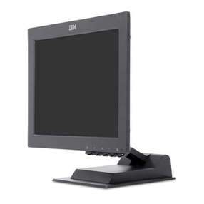
IBM 3276 Manual

IBt~1
3276 Control Unit Display Station
Setup Instructions GA1
S-2017-6
Please follow instructions, step by step,
in
the
sequence
that
follows.
Actions you should take are indicated by a box
(n),
~hich
is
also provided you
to
h~lp
you
k~rack
of
your progress.
Put
a check (
,J
)
in
the_
box (
~)
as you finish each action.
Note: DO
NOT
place objects
on
top
of
the display.
DO
NOT
block the display
vents.
CAUTION: The display station
weighs
about
45
kg
(100 lb).
Do
not
try
to
move
it
without
help. Communication Cable
"
ciz-~
Step 1
D
D
D
D
Obtain
the
following from
your
supervisor:
a. 3276 Device Cable
Attachment
chart,
required for Step
11.
b. 3276 Switch Settings chart, required for
Step
12.
c. Communication Cable Connection Instruc-
tions chart, required for Step 14
or
18.
Illustrations
of
the
above are shown on
the
last
page.
If
the
Encrypt/Decrypt feature (Identified
in
Step
13)
is
in.stalled, get help from your
security representative
at
Step 14.
© Copyright International Business Machines Corporation 1977, 1978, 1979, 1980.
Step 2
D Remove
the
Problem Determination Guide
and
the
Maintenance Information manual
from
the
envelope.
D Open
the
front
cover by pressing on
the
tab.
Printed
in
U.S.A.
1/80

D Remove the backing paper from
the
Problem
Determination Guide.
D Insert
the
Problem Determination Guide
in
the
keyboard with
the
hinged edge toward
the
front, tap it
int~
place, and close
the
cover.
Step 3
D Turn
the
keyboard over.
D Release the
document
holder by pressing the
catch.

D Place the Maintenance Information manual
in
the holder, and snap it closed.
Step 4
D Slide
the
communication cable [1.8
to
12
meters (6
to
40
feet) long] under
the
display
station, so
that
the
connector end shown
at
left
is
accessible from
the
front
of
the
3276.
D Remove the plastic safety catch
if
present, from the power
cord by breaking the catch.
Position
the
power cord
under
the
display station
and extend it toward
the
power outlet,
but
do
not
plug it
in
at
this time. Plastic Safety
Catch
Steps
-
Latch
,,,::.;:,...
_______
_
,,,.
...
11Pivot Pin
""'
/
,,
...
,
-=====
=.§-~
(behind cover)
D Open
the
front
cover by pushing
the
latch
away from you (toward
the
machine).
D Remove
the
front
cover by lifting it
off
the
pivot pins.

Step 6
Note: the voltage and frequency requirements for
this
unit
are
indicated on the label.
D Unlatch
the
retainer wire by pressing
in
and
to
the left
to
clear
the
latch; then lift and swing
to
the
left.
Don't
be afraid
to
apply
the
necessary force.
DRemove the wing nuts.
Retainer
Wire
in
Open
Position Stud
Fuse
\
'o
\ \
Power
Cord
~ ~
Step 7
Keyboard
~--...,Cable
DRemove
the
protective bag from
the
keyboard
cable connector.
D Place
the
keyboard cable clamp over
the
right-
hand stud.
Don't
be afraid
to
apply
the
neces-
sary force. Plug
the
keyboard cable connector
into
the
cable socket above
the
letters KEYBD.
D Install and tighten the wing nut.
Step 8
Ground
D Plug the communication cable connector into
the
cable socket above
the
letters 1/0.

Step 9
Ground
Wire ..... Replace
Lug
D
D
Retainer Wire
Bottom First
Swing
the
retainer wire across
the
cable
connectors. Insert
the
bottom
of
the
retainer
wire in
the
slot, and latch it
in
place. The
retainer wire keeps
the
connectors tightly
in
place; it therefore takes some extra force
to
latch it. Don't be afraid
to
apply
the
necessary
force.
Place
the
ground wire lug over
the
stud; install and tighten
the
wing nut.
Step 10
C'.l
I
On/Off 0
~
Switch
CJ @
®
D Place
the
power cord, communication cable,
keyboard cable, etc., so
they
do
not
interfere
with closing
the
front
cover.
~
D Install
the
front cover
on
the
pivot pins. Close
the cover, and slide
the
cover latch toward
you.
D Push
the
On/Off switch
(located to
the
left
of
the
screen)
to
Off.
\1\J
On
~~Off
D Plug
the
power cord
into
the
power outlet.
Step
11
To Other Terminal
Device Cable
CAUTION: Do
not
connect
or
disconnect
the
device cables during an electrical storm.
D Connect
the
device cables
to
the
ports on
the
back
of
the
3276, using
the
3276
Device
Cable Attachment
chart
obtained
in
Step
1.

Step 12 Address Keylock Key
in
Unlocked Position
D
D
g
Q
If
the
display station has an address keylock,
insert
the
key and turn it clockwise.
Grasp the
top
of
the
operator panel drawer in
the recess. Push it slightly
to
the
right, and
pull it toward you. The drawer will stop and
latch (at
the
first stop).
Drawer at
First Stop
Press Spring
Latch Here
Press the spring latch as shown, and continue
pulling until
the
drawer stops again (at
the
second stop).
Switches
Drawer
Fully Open
D
D
D
Release
Spring
Latch
Set
the
switches,.using
the
3276
Switch
Settings chart obtained
in
Step
1.
Ensure
the On/Off switch
is
Off before changing
any
of
the
switches.
Push
the
drawer into its original position.
If
the
display station has an address keylock,
turn
the
address keylock key counterclock-
wise
to
lock
the
drawer.
Step 13
Address Keylock
IL'--'---A,a/A Switch
Normal/Test Switch·
g-security
Keylock
Volume Control
Contrast Control
Brightness Control
Set
the
following (located
to
the
right of
the
screen) as indicated:
DD
Set
this switch
to
Normal.--"'--t•t]
Turn
the
volume
Test
control for
the
_____
___J.___
__,
audible alarm
(if present)
fully clockwise.
DTurn
the
contrast
control fully
__
__,,
counterclockwise.
D Turn
the
brightness
control fully
---"'
1------:=
clockwise.
DIf
the
display station
has a security keylock,
insert
the
key into
the
lock and
turn
the
key
clockwise (to
the
On
position).
_J-()t
(On)L~~
~(Off)
If
there
is
no security keylock,
the
cover
will have a filler plug
in
this location.
D
If
the
Encrypt/Decrypt
feature
is
installed,
the
security key will have three
positions, Off, On, and
_.
EWMK.
Do
not
turn
the security
key
to
the
EWM
K position.

Step 14
D
D
D
Move
the keyboard
to
a convenient position
in
front
of
the
display station.
If
the Loop Adapter feature
is
installed, refer
to the instruction obtained
in
step 1, and plug
the communication cable connector into
the
loop station connector.
Push the On/Off switch
to On (I).
1.
The on light should come on;
if
it does not, check with your
supervisor
to
make sure power
is
available at
the
power outlet.
~~On
~Off
On
~~
Light
~
2.
About 15 seconds after
the
unit
is
turned on:
a. A short horizontal line (cursor) will
appear at
the
upper-left corner
of
the
screen. Ignore any 8-digit number,
consisting
of
1
'sand/or
O's,
cursor
being under
the
first digit.
b. A horizontal line
will
appear across the
bottom
of
the
screen. (The area below
this line
is
the
Operator Information
Area.)
D Adjust
the
Brightness
~
control,
if necessary.
~
If
result 1
or
2 does
not
occur, retry by turning
the display station off, then
on
again.
If
result 1
or
2 still does
not
occur,
or
)C
~
nn
is
displayed record this step on a
3276/3278/
3279 Problem Report Form (GX23-0201
),
to
be
found with the papers shipped with the
display station.
D
If
the Encrypt/Decrypt feature
is
installed,
call your security representative
to
enter
a master key into
the
3276.
Step 15
Set
the
following switches (located
to
the
right
of
the
screen):
DFirst, set this switch
to
"A,a."...
a
A
Normal
DThen, set this switch to
Test.
~
...
)3
Expected Result: The screen, except on
Model 1
or
11, should fill up with characters.
Operator Information Area
Notes:
Model 1 or
11
All
Other Models
1.
The
cursor
appears
in
the upper-leftcorner,
the
first
position
of
the first line.
2.
There is a solidhorizontal line
at
the lower
part
of
the screen, below which
is
the
Operator Information Area.
If
the
above does not happen, fill
out
a
3276/3278/3279 Problem Report.Form
(GX23-0201), and notify your supervisor.

Step 16 Model No.
D
3276
I "
Serial
Nl.
Scan
the
top
two
lines
of
the
display. They should be
the
same as those shown below
for
the
model
number
of
your
display station. (The size and style
of
the
characters will vary by model.)
Model
1or11
!elouiC5)iaeelouu~~sbouaeiouael6unAEi0DA0YAEEIOUYCAEIOUAEi00AtiOoNabcdefehijklmnop
~rstuvwx~z••!~JjABCDEFGHIJKLMNOPQRSTUVWXYZ~SAC;*oT2345b7><[])()(
='"/''
:1!S¢t¥~~
Model
2,
3,
4,
12, 13,
or
14
Ae"IOuaeiouael6uiiAEi0DA0YAEEIOUYCAE"i00AE:i0uAEi0dNabcdefghijklmnopq,rstuvwxyzaigacJili
ABCDEFGHIJKLMNOPQRSTuvwxYzfllsAc;*·or2"34sb"7>
<c 1>c>c =·
..
/'
1:?
!
$¢£¥r.lt01234Sb7scia§
11
E!%_
D Scan
the
Operator Information Area
(bottom
of
screen, below
the
solid horizontal line).
The
characters
should be
the
same
as
those
shown below
for
the
model number
of
your display station. (The
_size
and
style
of
the
characters will vary by model.)
Model
1or11
Model
2,
3,
4,
12,
13,
or
14
oT234sit7>
<c1>c>c =·
..
/'
1:? !
S¢f.¥P.,lte1234Sb
7sqB§•e~-&.-.,
: +
...
-
............
",
.,
ae
1o~&ess;ae~1
o~u.c
If the lines
of
displayed characters are different from
the
above,
turn
the
display station
off
then
on,
and repeat this step.
If
the characters are still different, record this step on a
3276/3278/3279
Problem Report Form
(GX23-0201
),
to
be found with
the
papers shipped with the display station, and notify
your
supervisor.
/
Step 17
D
D
D
This step
is
to
ensure
that
each key
on
the
keyboard
works
correctly.
The
procedure
is
to
press each
key
on
the
keyboard,
observe
the
character
displayed
on
the
screen,
and
compare
this
character
with
that
shown in
the
keyboard
diagram below
for
the
key pressed.
In
this
diagram
the
keys are shown
with
the
character
that
should be displayed when
the
key
is
pressed.
Remember, go by
the
characters shown
in
the
diagram
not
by
the
characters
on
the
keyboard keytops.
The
cursor will move
tq
the
next
position
on
the
screen as each key
is
pressed. You may press
the
spacebar (blank)
after
each key
is
pressed
in
order
to
see
the
characters more easily as
they
appear
on
the
screen.
Notice
in
the
diagram
that
there
is
a
group
of
keys
at
the
extreme
right labeled
"a"
through
"I".
If
your
keyboard does
not
have
these
keys, cross
them
out
in
the
diagram.
Note: Some keys,
if
held
down
for
about
1second,
will
repeat the character. Also, during the
following
procedure, the
key
marked
CONTROL
in
the diagram must
not
be pressed.
Press,
one
at
a
time,
the
four
keys shown
in
the
diagram with
the
double
characters
mm, nn,
oo,
and pp,
and observe
the
characters displayed. These
four
keys each display
one
character
when
the
key
is
pressed and repeat
the
character
when
the
key
is
released.
Press
the
remaining keys,
one
by
one,
and
check
that
the
character
shown
in
the
diagram for
that
key
is
displayed.
If
the
displayed results differ
from
what
is
shown
in
the
diagram,
turn
the
display
station
off
and
on
again. Wait
for
the
display
to
reappear. Now
retry
this step.
If
the
displayed results
continue
to
be
different,
record this step
on
a
3276/3278/3279
Problem
Report Form (GX23-0201
),
to
be
found
with
the
papers shipped with
the
display station,
and
notify
your
supervisor.

Characters Displayed When
in
Test Mode
0BEE00000000000E-30ffi008
88
8@8~88000@0008
08000
08§3@008@@0@0888)08000
80
§800@3000@888§
00000
CONTROL~~
(blank) j@cB
L Labeled
"RESET"
on Typewriter
or
Data Entry keyboards
Labeled
"PF
10"
on Data Entry keypunch keyboards
If
present

Step 18
Again, use the diagram provided
in
Step 17, "Characters Displayed
When
in
Test Mode," not
the
charac-
ters on the keyboard,
to
identify
the
correct key to be pressed. The CONTROL key starts each check.
It
is
important
that
the
CONTROL key be used only when indicated.
If
a wrong key
is
used
or
a key
is
held down for more than 1 second, turn power off, then on,
to
restart this step.
D 1. Press
the
CONTROL key, then
the
C key, once.
-
thenC
All
previously entered characters are replaced
by
the test pattern.
D 2.
Press
the
CONTROL key, then
the
B key, once.
-
thenB
2
is
displayed
in
the first position of
the
Operator Information Area
at
the bottom
of
the screen.
D 3.
Press
the
CONTROL key, then
the
B key three times.
-then
B,
then
B,
then B
0appears
in
the
first position
of
the Operator Information Area.
D 4. Press
the
CONTROL key, then
the
M,
A,
B,
and C keys, once each.
-then
M,
then
A,
then
B,
then C
ABC
appears
at
the start
of
the first line
of
the display.
5. Set
the
Normal/Test switch
to
Normal. The test pattern
is
cleared from
the
screen.
Pull
out
the
operator panel drawer,
as
described
in
Step 12, until it stops and latches (at
the
first
stop). Check if the Machine Check light
is
off and the Test light
is
off
or
blinking;
if
so, push
the drawer
in
to
its original position; if not, report the symptom on a 3276/3278/3279 Problem
Report Form (GX23-0201
),
to be found with the papers shipped with the display station and
notify your supervisor.
One
of
the following 8-digit numbers should appear
in
the
first row on
the
screen.
11000000 Terminal adapter
is
not attached to the 3276.
11110000 One terminal adapter
is
attached
to
the
3276.
11111100 Two terminal adapters are attached to
the
3276.
11111111 Three terminal adapters are attached
to
the
3276.

The
3276
setup
is
completed.
If
your
display station has
the
Magnetic Accessory
Adapter
feature, a
cable with
connector
is
located on
the
left side
of
the
display. See
the
instruction
book
packed with
the
accessory
to
connect
it.
The
Selector Light Pen, APL,
Text,
and Magnetic
Slot
Reader features may now be checked by
performing
the
applicable checks
in
Section 4
of
the
3276
Problem Determination Guide, which
is
under
the
keyboard cover.
Notify
your
supervisor
that
the
3276
setup
is
completed, and
that
the
3276
communication
cable may
be
connected
to
the
communication facility according
to
the
instructions obtained
in
Step
1.
The
com-
munication cable must be
connected
in
accordance with local regulations.
After
the
communication cabl,e
is
connected,
the
3276
can
communicate
with
the
host.
Note: Retain this document for use
in
the event the units
are
relocated.

The following illustrations show charts
that
you are
to
obtain
in
Step 1, and
they
are taken from IBM
3270
Information Displav System:
IBM
3276
Control
Unit
Display Station Planning andSetup Guide,
GA
18-2041.
C.
Communications Cable Connection Instructions
Appendix C.
3276
Com
..
nkadon
Cable
Couection
lmlructionl
3276 Commanic.tionClble
CoRMCtion
lmtnlcliolll
3276
with
811
lntepated
M-
Albched too
N--
Uno
(11SIUOda-doonlyJ
B.
Switch Settings
3276 Swilch
~Uinp
Form
n.ooer-PM9!dr-t•locr9Wdto""9r•1olrtled1•..,•-·
To.-n-tom.-mi.
.•
._ltlelGOofthe~
......
._.
Putl'l11sl11hl1\ltottl9r
....
t.andpUHHl~¥0U.
Thtdr-"'ll1tc1PandlMCfl•tdlefirt11to11.
Ufltlel2J&hm
ft
Add,..
K..,1oc
..
fMIW<'tl,
in•rt
die..,
11110
die
loc
..
8llCf
tun!
die
U,
dodtwl•
un11I
1t
11C1C11.I
"-
Plftf
llaatld
Oft
tN
._..,,...,.oftflll
doorl,
9ndco1u1nue
1opWH
1111111
Ndr-
"°'"'•'"·
AIW¥Oll
"-wt
dle,..tdlel_..,.10
lfle
~
o.1-
.............
_ tNlck
IO
IH
cto.d
.........
Ill
"'9
J279Mltflll
Addr.-K•lock
,_,.,
1111'11
...,__,._.,.
clodi._and,......,.rtle...,J
8
Sw•ldt
off
....
3279
.,_-.
Sn
lttll
321•
.,....,._
,
.....
0r-
-l"'-510
m.-tlOJll
trM1-GMc:ir.t
...
""'
,....__
--
.....
DD
NOT
$1t...,
-tdln
itt1t
-
_,...,
w•itt...,.
t*"
ltl8• •re
cro-d
Ot.11.
D
s-•
on
...
J211.-....
0
Plytlhe
four-pronfAhlf
._....101heCGM111UnicdonCllble
...-.
NONSWITCHEO
9ntoftfour-pin
,...,_.~toft......._.lint.
A.
Device Cable
Attachment
DO
NOT
c'*""
CM
poli1oon
o1-1cn.
wt.ile POIWI'
"-·
°*""'9
• -•ldl
PIHi•ion
•;1e
.-
••on
'-no
Mfftt.
r---------------------------------.··
1u-1cftel,..t111d181'1111d"""'1
..
~11on.
Appendix
B.
3276
Onice
Cable Attadunen1
'271
....
0 UM
m.
table ano
ttw
fi.,re
below
10
connect
the
devK:e
cebl•
to
the 3276 por1L
..._
...
_._
1.
U•
• push·Mtd·1W•l1 mo11on
to
the
r.~1
to
connect
-1d
lock ttMde¥K:.
ublel
to
the
port
sockets.
2. Connect
IN
dnice
clble
MNntified for
port
1 to
the
pon
1 socket.
port
2
to
the
port
2 socket.
end'°
on. Connect
the
clbla
1n
numeric order, sterting
11
pon
1.
CAUTION
0o
.............
._.
......................
11Dnn.
INALU
.,._
---
L.n_
~--c.ai.
J2711.'!!!l!!I~
L_.,_
..
..
"'
ill
..
..
••
The
information
in
this publication
is
subject
to
change from time
to
time. Any such change will be reported in subsequent revisions.
··,Requests for copies
of
IBM
publications should be made
to
your
IBM
~'representative
or
the
IBM
branch office serving
your
locality.
th9
ON
or
0 Set
the
B
switdt
pos11ions
6, 7.
end
8
to
the
ON
or
OFF
P011it1ons
dtectld
in
the
tlbl•
below.
d
'"the
I
"'
c=:,
~
f:.:81:.:~I
i I ! !
d-t--1
Ou1ck
ref1n1na
of
SWttch wtt1ngs for
hne
1PMd wlec:t1on
"locetlld
below
the
Bswitch
1n
the
Clf)er1t0t
Panel
Drewer.
@@@
li:5J'•••
..
L!:!J
Sv•am
7 ...u..---
.......
j
5"..,.SOlCllSC
-ldlto-SOLC
F-':
I I
0Set
the Communie81e/
LOCllMia:ftlOlfle
Canwnunoat•
lupl
Oii
Laal
lctownl
posnoon
dleck8d1n
....
lllbl8
.......
__
-·
Address comments concerning
the
content
of
this publication
to
IBM
Corporation, Dept.
825J,
1133 Westchester Avenue, White Plains, N.Y.
10604. I
BM
may use
or
distributeany
of
theinformation you supply in any
way it believes appropriate
without
incurring any obligation whatever.
You may, of course, continue
to
use the information you supply.
IBM World Trade Americas/Far East Corporation
21
IBM
®
lnlernationat Business Machines Corporation
Data
Processing
Di¥ision Town
of
Mount Pleasant, Rout& 9, North Tarrytown. N.Y
.•
U.S.A. 10591
1133 Westchester Avenue. While Plains, N.Y. 10604 IBM World Trad&
Europe/Middle
East/Africa
Corporation
360 Hamilton Avenu&, While Plains,
N.
Y.,
U.S.A. 10601
Other IBM Monitor manuals

IBM
IBM ThinkVision L190 User manual

IBM
IBM T541A User manual

IBM
IBM ThinkVision L150 User manual

IBM
IBM 5154-001 Application guide

IBM
IBM ThinkVision 6734-AB9 User manual

IBM
IBM ThinkVision L190P User manual

IBM
IBM E74M User manual

IBM
IBM P275 User manual

IBM
IBM 3191 User manual

IBM
IBM ThinkVision L150 User manual

IBM
IBM 2250 3 User manual

IBM
IBM 7316-TF4 User manual

IBM
IBM T84H User manual

IBM
IBM T T 541 User manual

IBM
IBM ThinkVision L200p User manual

IBM
IBM C50 User manual

IBM
IBM 9497DG0 - T 86D - 18.1" LCD Monitor User manual

IBM
IBM 3274 Technical manual

IBM
IBM P260 Original operating instructions

IBM
IBM L190(9329-AB9) User manual