3 Operating
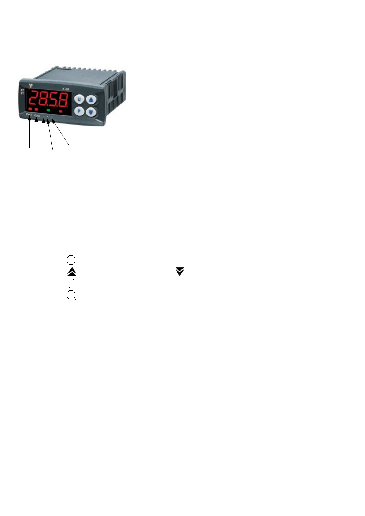
3.1 K3 display description
1 : OUT1 : pump of the wet air circuit in operation
2 : OUT2 : pump of the dry air circuit in operation
3 : - : value of the measured humidity is lower than the setpoint value
4 = : value of the measured humidity is stabilized at the setpoint value
5 : + : value of the measured humidity is higher than the setpoint value
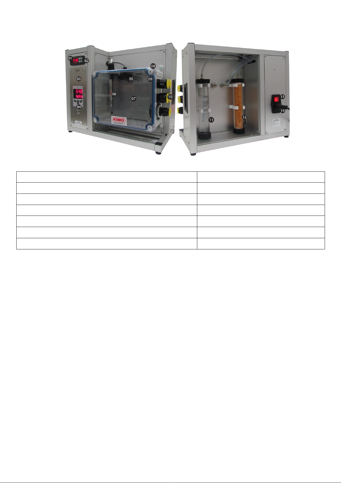
3.2 Operating principles
The GH 00 is a device which allows to generate points of relative humidity on a range from 10 to 8 % HR. It works on the
principle of a mix of moist air and dry air in different proportions, in order to obtain the required relative humidity value. For
the generator works optimally, it must be placed in the most stable room in temperature (between 20 and 2 °C). This
condition will define the homogeneity in humidity of the generator. Once the generator is properly installed and turned on,
simply select the threshold value of the required relative humidity.
3.3 Enter a setpoint value
To enter a setpoint value :
➢Press on The screen starts flashing in displaying SP1 and the actual setpoint value.
➢Press on to increase the setpoint value or on to decrease the setpoint value.
➢Press on to validate.
➢Press on during 3 seconds to return to the normal display.
3.4 Performances
The stability of the GH 00 regulation allows to have a regulated setpoint value at ± 0.1% RH. It is able to pass from 10 to
8 % RH in 3 minutes and from 8 to 10% RH in 30 minutes. However, the durations can vary according to the
consumables wear condition, if the rise and fall times become more longer, verify their conditions.
The homogeneity in dry temperature is 0,1°C in a restricted volume, it is therefore advised in order to have a precise
measurement to put the probe in the middle of the housing.
3.5 Use advice
The measuring chamber must be always airtight. The ball of the overpressure control exhaust outlet (see 08 instrument
description chapter) must turn when the pump is in operation.
If not, check that the front part of the measuring chamber is well closed and that the cable glands are well blocked.
7
P
P
U
123 4