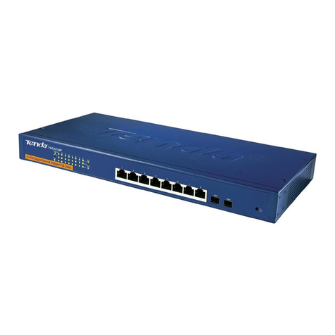
Tenda TEF1210P-8-150W User manual


- i -
Copyright Statement
© 2016 Shenzhen Tenda Technology Co., Ltd. All rights reserved.
Tenda is a registered trademark legally held by Shenzhen Tenda Technology Co., Ltd.
Other brand and product names mentioned herein are trademarks or registered trademarks
of their respective holders. Copyright of the whole product as integration, including its
accessories and software, belongs to Shenzhen Tenda Technology Co., Ltd. No part of this
publication can be reproduced, transmitted, transcribed, stored in a retrieval system, or
translated into any language in any form or by any means without the prior written
permission of Shenzhen Tenda Technology Co., Ltd.
Disclaimer
Pictures, images and product specifications herein are for references only. To improve
internal design, operational function, and/or reliability, Tenda reserves the right to make
changes to the products without obligation to notify any person or organization of such
revisions or changes. Tenda does not assume any liability that may occur due to the use or
application of the product described herein. Every effort has been made in the preparation of
this document to ensure accuracy of the contents, but all statements, information and
recommendations in this document do not constitute the warranty of any kind, express or
implied.

- ii -
Preface
Thank you for choosing Tenda! Before using your device, please read this guide carefully.
Conventions
This guide applies to TEF1210P-8-150W, TEF1218P-16-250W and TEF1226P-24-440W.
Model
Description
TEF1210P-8-150W
8+2G Web Smart PoE Switch
TEF1218P-16-250W
16+2G Web Smart PoE Switch
TEF1226P-24-440W
24+2G Web Smart PoE Switch
Typographical conventions in this User Guide:
Item
Presentatio
n
Example
Button
Bold
“Click the Save button” can be simplified as “Click
Save”.
Menu
Bold
“The menu Basic” can be simplified as Basic.
Continuous Steps
>
Click Wireless > Basic
Symbols in this User Guide:
Item
Meaning
Note
This format is used to highlight information of importance or special
interest. Ignoring this type of note may result in ineffective
configurations, loss of data or damage to device.
Tip
This format is used to highlight a procedure that will save time or
resources.

- iii -
How to Obtain Latest Product Info
For latest product information, visit Tenda official website http://www.tendacn.com and input
the corresponding product model in the search bar.
Technical Support
United States Hotline: 1-800-570-5892
Canada Hotline: 1-888-998-8966
HongKong Hotline: 00852-81931998
Skype: Tendasz
Website: http:// www.tendacn.com

- iv -
Contents
1 Device Login.................................................................................................................... 1
1.1 Login............................................................................................................................ 1
1.2 Logout ......................................................................................................................... 4
1.3 Layout Introduction...................................................................................................... 4
2 System Administration.................................................................................................... 6
2.1 System Info ................................................................................................................. 6
2.2 User Management....................................................................................................... 8
2.3 Reset........................................................................................................................... 9
2.4 Reboot......................................................................................................................... 9
2.5 Firmware Upgrade..................................................................................................... 10
3. Port Management ......................................................................................................... 13
3.1 Port Configuration...................................................................................................... 13
3.2 Port Mirroring............................................................................................................. 17
3.2.1 Overview ............................................................................................................. 17
3.2.2 Port Mirroring Configuration ................................................................................ 18
3.2.3 Application Scenarios.......................................................................................... 19
3.3 Port Statistics ............................................................................................................ 22
3.4 Rate Limit.................................................................................................................. 23
4 Link Aggregation........................................................................................................... 25
4.1 Overview ................................................................................................................... 25
4.2 Link Aggregation Configuration ................................................................................. 25
5 Network Extension ........................................................................................................ 27
6 PoE Management........................................................................................................... 29
7 VLAN Management........................................................................................................ 31
7.1 Overview ................................................................................................................... 31
7.2 Port VLAN ................................................................................................................. 37
7.2.1 Configuration Wizard........................................................................................... 37
7.2.2 VLAN Port Configuration..................................................................................... 37
7.2.3 Application Scenarios.......................................................................................... 42
7.3 ONE KEY VLAN........................................................................................................ 44
7.3.1 Configuration Wizard........................................................................................... 44
7.3.2 ONE KEY VLAN.................................................................................................. 44

- v -
7.4 802.1Q VLAN ............................................................................................................ 46
7.4.1 Configuration Wizard........................................................................................... 46
7.4.2 802.1Q VLAN Configuration................................................................................ 46
7.4.3 Application Scenarios.......................................................................................... 51
8 Device Management...................................................................................................... 55
8.1 MAC Binding ............................................................................................................. 55
8.1.1 Overview ............................................................................................................. 55
8.1.2 Configuring MAC Binding.................................................................................... 56
8.1.3 Application Scenarios.......................................................................................... 57
8.2 QoS........................................................................................................................... 59
8.2.1 Overview ............................................................................................................. 59
8.2.2 Configuring QoS.................................................................................................. 60
8.3 STP ........................................................................................................................... 62
8.3.1 Global setting of STP .......................................................................................... 67
8.3.2 Port setting.......................................................................................................... 71
8.4 IGSP.......................................................................................................................... 72
8.5 SNMP........................................................................................................................ 75
8.5.1 Overview ............................................................................................................. 75
8.5.2 Configure the SNMP ........................................................................................... 77
8.5.3 Application Scenarios.......................................................................................... 81
9 Exit.................................................................................................................................. 84
10 Configuration Management ........................................................................................ 85
10.1 Back up the system configuration information......................................................... 85
10.2 Restore configuration information from files ............................................................ 85
Emission and Safety Statement...................................................................................... 87

Device Login
- 1 -
1 Device Login
1.1 Login
The switch has the function of Web administration. Based on the function, administrators
could manage and maintain it in an intuitive way.
The first access to the switch allows you to enter the Web administration page through a
web browser by the default login info. The default info of Web login includes:
Login info
Default settings
IP address
192.168.0.1
Username
admin
Password
admin
Log in to the Web administration page: (suppose that the login info is default)
1. Use an Ethernet cable to connect a computer and the RJ45 port of the switch;
2. Set the local IP address as “192.168.0.X” (X is 2~254), sharing the same network
segment with but different from the IP address of the switch. Subnet mask is set as
255.255.255.0;

Device Login
- 2 -
3. Launch a web browser, input IP address of the switch “192.168.0.1”, and then tap Enter
on the keyboard;
4. In the Web administration page, input “admin” for username and password respectively,
then click Login
5. Upon entering into the Web administration page, you can review or modify configuration
of the switch.

Device Login
- 3 -
Tip
The Web administrations of 8/16/24-Port 10/100Mbps + 2 Gigabit Web Smart PoE Switches
are similar, with just a little difference in port numbers. We take 16-Port 10/100Mbps + 2
Gigabit Web Smart PoE Switch as an example. (Model: TEF1218P-16-250W).

Device Login
- 4 -
1.2 Logout
Click Logout in the left navigation bar and you will safely exit the page.
1.3 Layout Introduction
The Web administration page is totally divided into three parts: the first and second-level
navigation bar, the third-level navigation bar, configuration zone, as shown below:
Click to safely exit the page.
1
2
3

Device Login
- 5 -
S/N
Name
Description
1
The first and
second-level
navigation bar
The navigation bar takes advantage of navigation tree to arrange
Web function menu. It is very easy for users to select the function
menu. The selected functions will be displayed in the navigation
zone.
2
The third-level
navigation bar
3
Configuration
zone
It is designed for users to configure and review the device.
Tip
Click at the top right corner and you can get a view of brief introduction of the page
settings.

- 6 -
2 System Administration
System Administration consists of five parts: System Info, User Management, Reset,
Reboot, and Firmware Upgrade.
2.1 System Info
Here you can see the basic info of the switch, and configure the IP address or MAC aging
time.
Click Administration to enter page.
Parameter specification:
Header Entry
Description
Software Version
Display version info and release time
Hardware Version
Display hardware version info
MAC address
Display MAC address of the switch

System Administration
- 7 -
Header Entry
Description
VLAN
Management
When VLAN mode is 802.1Q VLAN, the management VLAN of the
switch is 1 and unavailable to be modified.
Note
The switch only can be visited when the computer is connected to the
VLAN port member (PVID of the port is 1).
Device Name
The model of the device, e.g, the name of 16-Port 10/100Mbps + 2
Gigabit Web Smart PoE Switch is “TEF1218P-16-250W”.
DHCP Client
Enable/Disable DHCP client function
Enable: The switch will automatically acquire IP address, subnet
mask and gateway from the DHCP server
Disable: Manual settings are required for IP address, subnet mask
and gateway to manage the device and connect to the Internet.
Note
When DHCP Client is enabled, you must check the switch’s IP address
from DHCP server before your next access to the Web administration
and use this IP address to login.
IP address
The IP address of the switch. The default one is 192.168.0.1 and can be
modified when DHCP client is disabled.
Also, it is the management IP address of the switch which can be used
to log in to the Web administration.
Note
Once IP address is altered, it is necessary to change the IP address of
the governing computer to keep its network segment consistent with that
of new one. And only the new IP address can be used to log in to the
Web administration.
Subnet Mask
The subnet mask of the IP address. The default one is 255.255.255.0,
and can be modified when DHCP client is disabled.
Gateway
It is the gateway address of the switch by default. It can be modified
when DHCP client is disabled.
MAC Aging
It is the dynamic MAC aging time and suggested to keep the default

System Administration
- 8 -
Time
value “300s”.
Tip
Less aging time will drive the dynamic MAC address table to refresh
more frequently and destination addresses in the received data
packages cannot be found. As a result, the switch is only capable of
broadcasting these Packages to all ports, at the price of damaging the
switch performance.
Much aging time will force the dynamic MAC address table to save up
more stale addresses until it uses up all address tables. Eventually, the
switch fails to refresh them upon changing network.
2.2 User Management
Click User Management and you can modify the login User Name and Password, thus to
prevent unauthorized users from accessing to the Web administration to change settings
and bring about negative effects on your network.
Click Administration > User Management to enter the page below.
Configuration Steps:
1. User Name: the character size is 1~15, only made up of English letters, digits and
underline, and is started with a letter;
2. Password: the character size is 1~15, only made up of English letters, digits, underline
and hyphen;

System Administration
- 9 -
3. Confirm Password: enter the password once again;
4. Click OK
The switch will reboot automatically when new user name and password are created. The
new user name and password are required for the next access to the Web administration.
2.3 Reset
The function of reset is available when you want to clear all configurations and restore the
switch to factory default settings.
Click Administration > Reset to enter the page below.
In case of forgetting IP login address or user name/password, you can use the Reset button
to reset the switch. The procedures are shown below:
1. Under power-up state, use a needle-shaped object to press the Reset button on the front
panel of the switch for 6s seconds;
2. Wait for about 20 seconds until SYS LED is blinking again.
Tip
Upon resetting the switch”, IP address is “192.168.0.1”, user name and password are both
“admin”.
2.4 Reboot
Reboot the switch to release partial cache, remove unwanted messages, thus to keep it

System Administration
- 10 -
running freely. Sometimes, reboot the switch to solve some problems such as deadlocks,
inability to access to the Web administrator page.
Click Administration > Reboot to enter the page below.
Note
During reboot, please note that powering off will damage the switch.
2.5 Firmware Upgrade
Go to Tenda official website http://www.tendacn.com to download the latest firmware
corresponding to the switch for more value-added functions and more stable performance.
The login password is required to enter prior to firmware upgrade (the default login
password is “admin”).
Click Administration > Firmware Upgrade to enter the verification page of firmware
upgrade.

System Administration
- 11 -
How to upgrade software:
1. Go to http://www.tendacn.com to download the latest upgrading file corresponding to the
switch to the local computer;
2. Log in Web administration page, then click Administration > Firmware Upgrade to
enter the verification page of Firmware Upgrade;
3. Input the login password of the Web Administration in the input box after “Password”,
then click OK
4. Pop up a dialog box, click OK

System Administration
- 12 -
Note
During upgrade, please note that powering off will damage the switch. In case of abrupt
power outage, please re-upgrade it; if unable to access to the Web Administration after the
outage, please contact the technical support for maintenance.
5. Enter the page of Firmware Upgrade, click Choose file to select an upgrade file from the
local computer and load it;
6. Click Update;
7. Pop up a dialog box, click OK
Note
No interrupting. Wait for the button OK to appear and click OK when it turns highlighted.
Otherwise, upgrade it again.
8. A progress bar is shown. When no progress is left for the progress bar, wait for the
following page to appear and upon the button OK turning highlighted, click OK

- 13 -
3. Port Management
Port Management covers four parts: Port Configuration, Port Mirroring, Statistics, and Rate
Limit.
3.1 Port Configuration
Here you can check and set the basic parameters of all ports. Click Port Management to
enter the page below.
Parameter setting specification:
Header entry
Description
Check the box at the front of the corresponding port number to select
that port. Check the box at the top to select all of the ports.
Enable/Disable
Enable/Disable the port.
Enable: Enable the forwarding function of the selected port.
Disable: Disable the forwarding function of the selected port.

Port Management
- 14 -
Header entry
Description
Enable/Disable
(Continued)
Note
Only when the port is enabled can it forward data properly. Disable the
unused port; reopen it when needed, to reduce the power consumption.
Speed/Duplex
Select the transmission speed and mode of the port.
FDX refers to Full Duplex, meaning that the port can receive and send
messages at the same time; HDX refers to Half Duplex, meaning that
the port can either receive or send messages at the same time.
Port G1/SFP1 and G2/SFP2 support 1000M/FDX and Auto-negotiation;
other ports support 10M/FDX, 10M/HDX, 100M/FDX, 100M/HDX and
Auto-negotiation.
When the switch is being linked with the terminal network equipment,
make sure of the speed and duplex according with the two ports to keep
nice communication.
Generally, advise to keep the default setting Auto.The transmission
speed and mode will be determined by the auto-negotiation of the local
port and the terminal port.
Priority
Select the port priority when setting QoS.
Flow Control
Enable/disable the flow control function of the selected port.
When the flow control of the switch and the terminal equipment are all
enabled, if some port congestion of the switch occurs, the port will send
the pause frame to the terminal equipment that will be suspended to
send data after receiving the pause frame; meanwhile, when one port of
the switch receives a pause frame, the port also will be paused to send
data.
By default, the port flow control is enabled.
Note
Enable the flow control to avoid the data packet loss caused by the
inconsistency of the sending and receiving rate. Yet that will also affect
the communication rate of the data source port and other facilities.
Please be careful with this function when linking the network port.
Storm Control
Enable/disable the broadcasting storm control function of the selected
port. By default, the storm control is disabled.
This manual suits for next models
2
Table of contents
Other Tenda Switch manuals

Tenda
Tenda TEG1216T User manual

Tenda
Tenda TEG1008S User manual

Tenda
Tenda TEG1024D User manual

Tenda
Tenda TEG1210P User manual

Tenda
Tenda TEG1024G User manual

Tenda
Tenda S108 User manual

Tenda
Tenda TEG1224T User manual

Tenda
Tenda TEG3224P User manual

Tenda
Tenda TEG1016D User manual

Tenda
Tenda TEG3224T User manual