Ice-O-Matic Gourmet UCG Series Manual

MODELS‐UCG45,UCG65,UCG85,UCG105,UCG135,UCG165
InstallationandServiceManual
Ice‐O‐Matic
11100E.45
th
Ave.
Denver,Colorado80239
1‐866‐PURE‐ICE
PartNumber9081522‐02
Revision03/21
UCGGOURMETSERIESUNDERCOUNTER

UCGGOURMETSERIESUNDERCOUNTER
pg.2

UCGGOURMETSERIESUNDERCOUNTER
pg.3
GENERALINFORMATIONANDINSTALLATION
A. INTRODUCTION
Thismanualprovidesthespecificationsandthestep‐bystepproceduresfortheinstallation,startup,
operation,cleaning,andmaintenancefortheIce‐O‐MaticUCGUndercounterSeriesicemakers.To
retainthesafetyandperformancebuiltintothisicemaker, itisimportant thatinstallationand
maintenancebeconductedinthemanneroutlinedinthismanual.
Formoretechnicalinformation,refertowww.iceomatic.com.
B. UNPACKINGANDINSPECTION
1. CallyourauthorizedIce‐O‐MaticDistributororDealerforproperinstallation.
2. Visuallyinspecttheexteriorofthepackagingandskid.Anyseveredamagenotedshouldbe
reportedtothedeliveringcarrier.
3. Cutandremovetheplasticstripsecuringthecartonboxtotheskid.Cutopenthetopofthe
carton andremove the protection sheet. Pullout thecorner posts,and thenremovethe
carton.
4. Removethefrontpaneloftheunit,andinspectforanyconcealeddamage.Notifythecarrier
ofanyconcealeddamage.
5. Checkthatrefrigerantlinesdonotrubagainstortouchotherlinesorsurfaces,andthefan
blademovesfreely.
6. Checkthatthecompressorfitssnuglyontoallitsmountingpads.
7. Removeallinternalsupportpackagingandmaskingtape.
8. Useaclean,dampclothtowipethesurfacesinsidethestoragebinandtheoutsideofthe
cabinet.
9. Seedataplateontherearsideoftheunitandcheckthatlocalmainvoltagecorrespondswith
thevoltagespecifiedonit.
10. Registertheunitatwww.iceomatic.com/warranty.
11. Installandadjustlegsprovidedtoleveltheunit.
C. LOCATIONANDLEVELING
1. Positiontheunitintheselectedpermanentlocation.Criteriaforselectionoflocationinclude:
a. Minimum room temperature of 50˚F (10˚C) and maximum room temperature of
100˚F(40˚C).
CAUTION:Incorrectvoltagesuppliedtotheice
makerwillvoidyourpartsreplacementprogram.
WARNING:Thisicemakerisdesignedforindoorinstallationonly.
Extendedperiodsofoperationattemperaturesexceedingthefollowing
limitationswillconstitutemisuseunderthetermsoftheIce‐O‐Matic
Manufacturer’sLimitedWarranty,resultinginlossofwarrantycoverage.

UCGGOURMETSERIESUNDERCOUNTER
pg.4
b. Minimum water inlet temperature of 40˚F (5˚C) and maximum waterinlet
temperatureof90˚F(35˚C).
c. Wellventilatedlocation.
d. Serviceaccess:adequatespacemustbeleftforallserviceconnectionsthroughthe
rearoftheicemaker.Aminimumclearanceof6”(15cm)mustbeleftatthesidesof
theunitforroutingairdrawnintoandexhaustedoutofthecompartmenttomaintain
propercondensingoperation.
2. Leveltheunitinboththelefttorightandfronttoreardirections.
D. ELECTRICALCONNECTIONS
Seedataplateforcurrentrequirementstodeterminewiresizetobeusedforelectricalconnections.
AllIce‐O‐Maticicemakersrequireasolidearthwire.Theyaresuppliedfromthefactorycompletely
pre‐wiredandrequireonlyelectricalpowerconnectionstotherearoftheunit.Makesurethe
icemakerisconnectedtoitsowncircuitandindividuallyfused(seedataplateforfusesize).
Themaximumallowablevoltagevariationshouldnotexceed‐10%and+10%ofthedataplate
rating. Low voltage can cause faulty functioning and may be responsible for serious damage to the
overload switch and motor windings. Check voltage on the line and the ice maker’s data plate
beforeconnectingtheunit.
E. WATERSUPPLYANDDRAINCONNECTIONS
GENERAL
Whenchoosingthewatersupplyfortheicemakerconsiderationshouldbegivento:
a. Lengthofrun
b. Waterclarityandpurity
c. Adequatewatersupplypressure
Sincewateristhemostimportantsingleingredientinproducingice,thethreeitemslistedaboveare
extremelysignificant.Lowwaterpressure,below14psi(1bar),maycausemalfunctionoftheice
maker.Watercontainingexcessivemineralswilltendtoproducecloudyicecubes,inadditiontoscale
build‐uponpartsofthewatersystem.
WATERSUPPLY
Connectthe¾”malefittingofthesolenoidwaterinletvalve,usingtheflexibletubesupplied,tothe
cold‐water supply line with regularplumbing fitting and ashut‐off valve installed in an accessible
positionbetweenthewatersupplylineandtheunit.Ifwatercontainsahighlevelofimpurities,itis
advisabletoconsidertheuseofanappropriatewaterfilter.
NOTE:Allexternalwiringshouldconformtonational,
state,andlocalstandardsandregulations.

UCGGOURMETSERIESUNDERCOUNTER
pg.5
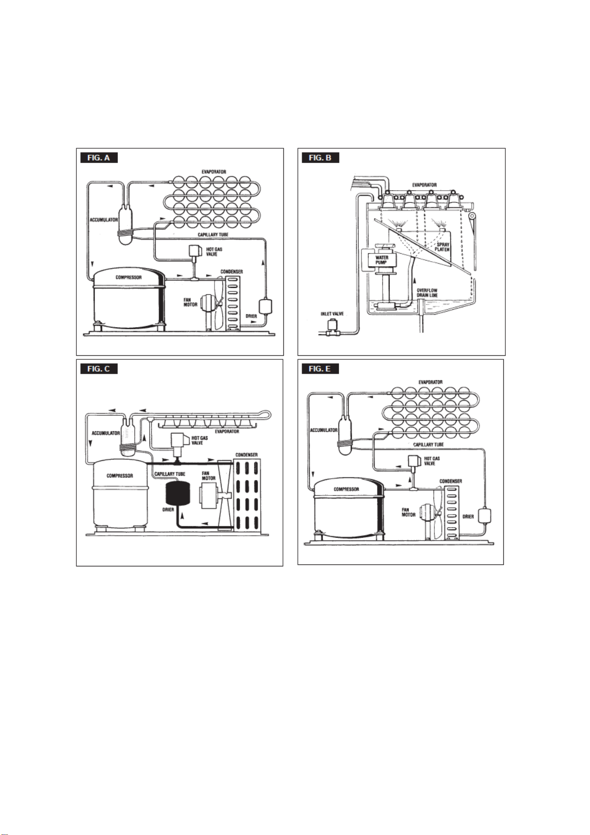
WATERSUPPLY‐Watercooledmodels(UCG165)
Thewatercooledversionsrequiretwoseparateinletwatersupplies,oneforthewatersprayedfor
makingtheicecubesandtheotherforthewatercooledcondenser.Connectthe3/4"malefittingof
thewaterregulatingvalveusingtheflexiblehosesuppliedwiththeunittothecoldwatersupplyline
with regular plumbing fitting and a shut‐off valve installed in an accessible position between the
watersupplylineandtheunit.
WATERDRAIN
Therecommendeddraintubeisaplasticorflexibletubewith18mm(3/4")I.D.runsto an open
trappedandventeddrain.Whenthedrainisalongrun,allow3cmpitchpermeter(1/4"pitchper
foot).Averticalopenvent,attheunitdrainconnection,isalsorequiredforpropersumpdrainage.
WATERDRAIN‐Watercooledmodels
Thewaterdrainlinefromthecondenser,onwatercooledversions,isinternallyconnectedwiththe
drainfittingoftheunit.Itisstronglyrecommendedthereforetoinstallaverticalopenventonunit
drainlinehighpointtoensuregooddrainingandtodirectthedrainlinetoatrappedandvented
floordrainreceptacle.Thistomakesureoftheproperflowofthedrainedwateras,incaseofpoor
drainage,thewaterranningoutfromthecondensermayinopportunelyflow,throughtheunitdrain
tubing,intotheicestoragebin.
F. FINALCHECKLIST
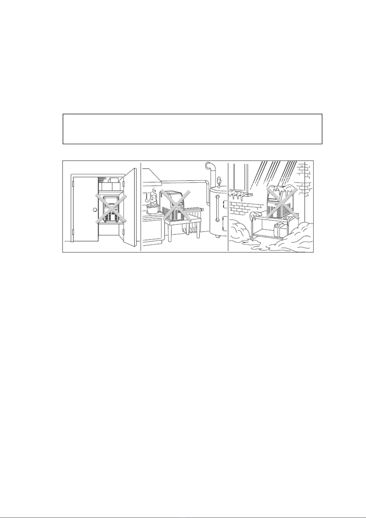
1. Istheunitinaroomwheretheambienttemperaturesarewithinaminimumof50˚F(10˚C)
eveninwintermonths?
2. Isthereatleasta6”(15cm)clearancearoundtheunitforproperaircirculation?
3. Istheunitlevel?(IMPORTANT)
4. Havealltheelectricalandplumbingconnectionsbeenmade,andisthewatersupplyshut‐off
valveopen?
5. Hasthevoltagebeentestedandcheckedagainstthedataplaterating?
6. Hasthewatersupplypressurebeencheckedtoensureawaterpressureofatleast14psi(1
bar)?
7. Checkallrefrigerantlinesandconduitlinestoguardagainstvibrationsandpossiblefailure.
8. Havetheboltsholdingthecompressordownbeencheckedtoensurethatthecompressoris
snuglyfittedontothemountingpads?
9. Havethebinlinerandcabinetbeenwipedclean?
10. Hastheowner/userbeengiventheInstallationandServiceManualandbeeninstructedon
theimportanceofperiodicmaintenancechecks?
11. Hastheunitbeenregisteredforwarranty?Checkforcorrectmodelandserialnumberagainst
theserialplate.
NOTE.Thewatersupplyandthewaterdrainmustbe
installedtoconformwiththelocalcode.Insomecasea
licensedplumberand/oraplumbingpermitisrequired.

UCGGOURMETSERIESUNDERCOUNTER
pg.6
12. HastheownerbeengiventhenameandthephonenumberoftheauthorizedIce‐O‐Matic
ServiceAgencyservinghim/her?
G. INSTALLATIONPRACTICE
H.OPERATINGINSTRUCTIONS
STARTUP
Afterhavingcorrectlyinstalledtheicemakerandcompletedtheplumbingandelectricalconnections,
performthefollowing“start‐up”procedure.
UCG45/65/85/105
A‐Removetheunitfrontpanelandlocatethecleaningswitchonthecontrolbox.
B‐Fill Reservoir with cleaningswitchincleaningposition(II).Thiswillclosetheelectricalcircuittothe
waterinletvalveandtothehotgasvalve.
C‐SwitchONthepowerlinedisconnectswitch.Unitwillstartupinwaterfillingphasemode.During
thisphasethecomponentsenergizedare:
WATERINLETSOLENOIDVALVE
HOTGASSOLENOIDVALVE
TheWaterpumpandtheFanmotorarealsoinoperation.
D‐Letunitstayinwaterfillingphasemodeforaboutthree/fourminutestillwateriscomingoutfrom
thedrainhose,thenmovethecleaningswitchtotheoperationposition(I).
WARNING:Thisicemakerisnotdesignedforoutdoorinstallationandwillnotfunctionin
ambienttemperaturesbelow50˚F(10˚C)andabove100˚F(40˚C).Thisicemakerwill
malfunctionwithwatertemperaturesbelow40
˚
F(5˚C)orabove90
˚
F(35˚C).

UCGGOURMETSERIESUNDERCOUNTER
pg.7
UCG135/165 (BOARD)
E‐GivepowertotheunittostartitupbyswitchingONthepowerlinemainswitch;theunitwill
startautomaticallyindefrostcyclewiththefollowingcomponentsenergized:
WATERINLETSOLENOID
VALVEHOTGASVALVE
COMPRESSOR
ELECTRONICTIMER
OPERATIONALCHECKS
A. Theunitnowstartsitsfirstfreezingcyclewiththefollowingcomponentsinoperation:
COMPRESSOR
WATERPUMP
FANMOTORinaircooledversion
B. Checktoseethroughtheicecurtainthatthespraysystemiscorrectlyseatedand
thatthewaterjetsuniformelyreachtheinterioroftheinvertedcupmolds;alsomakesurethat
theplasticcurtainishangingfreelyandthereisnotexcessivewaterspillingthroughit.
C. Theicemakingprocesstakesplacethereby,withthewatersprayedintothemoldsthatgets
graduallyrefrigeratedbytheheatexchangedwiththerefrigerantflowingintotheevaporator
serpentine.
D.OnunitsUCG45/65/85/105whentheevaporatortemperaturereachesapresetvaluethe
evaporatorthermostatorcubesizecontrolchangesitscontacts;thefreezingcycleendsandstarts
thedefrostorharvestcycle.
E. OnmodelsUCG135/165freezingcycleiscompletedthroughanelectronictimerenergizedby
theevaporatorthermostat.Itstartswhenthecubesizethermostat/controlbulb(pigtail)locatedon
theevaporatorserpentinereachesatemperatureofapprox.‐15°C(5°F).
F.
Check,duringthefirstdefrost/harvestcycle,thattheincomingwaterflowscorrectlyintothe
sumpreservoirinordertore‐fillitandthe
esurplus
overflowsthroughtheoverflowdraintube.
NOTE.Duringthedefrostcycle,thewaterinlet
solenoidvalveisenergized.Thewaterflows
throughthevalvetothebacksideofthe
evaporatorplatenandthendowntofillupthe
i c e m a k e r s u m p t a n k f o r t h e n e x t f r e e z i n g c y c l e .
OnunitsUCG135/165theadditionalTime(12')ofthefreezingcyclestartswhenthecubesize
thermostatcontrolbulb(pigtail)locatedontheevaporatorcoilreachesatemperatureofapprox.‐
15C.Freezingtimewillrangebetween20and22minutesina21Cambienttemperature,longerif
abovethistemperatureandshorterifbelow.ThentheunitgoesdirectlyintotheDefrostCycle.The
averagecompletecycletimeisbetween23and25 minutes.

UCG GOURMET SERIES UNDERCOUNTER
pg. 8
G.
Check the texture of ice cubes just released. Right size must have a small depression (about 5-6
mm) in their crown.If not, wait for the second defrost/harv before performing any adjustment.
H.
If required on model UCG 45/65/85/105, the length of the freezing cycle can be modified by
turning the knob of the cube size control or evaporator thermostat located in
frontofthe
machineuntilthedesiredsizeisachieved.
if the temperature
of the room in which
the machine is place
is below 20°C, the
cubes will tend to be
partly hollowed out
(see fig. on right).
If, on the other
hand, the room
temperature is
above 30°C the
cubes produced will
have a jagged rim of
ice around the
crown.

UCGGOURMETSERIESUNDERCOUNTER
pg.9
Ifitisthoughtnecessary,theabovesituationscanberectifiedby,inthefirstcase,turningthe
controlknob(aslittleorasmuchasisrequired)clockwiseand,inthesecondcase,turningthe
knobtotherightcounterclockwise.
Itshould,however,berememberedthatiftheroomtemperaturereturnslatertothe20 30C
range,theknobindicatormustonceagainbeturnedtothepreviousposition.
Iftheicecubesareshallowandcloudy,itispossiblethattheicemakerrunsshortofwater
duringtheendofthefreezingcycleor,thequalityofthesuppliedwaterrequirestheuseofan
appropriatewaterfilterorconditioner.
I.
Attheendofthedefrostorharvestcycleholdahandfuloficecubesagainstthebulbofthe
storagebinthermostat;theicemakerswitchOFFinaboutone‐twominutes.Takeouttheice
fromthestoragebinthermostat.Theicemakershouldrestartautomaticallyinthree‐four
minutes.
J.
Re‐fittheunitfrontpaneltheninstructtheowner/useronthegeneraloperationoftheice
machineandaboutthecleaningandcareitrequires
PRINCIPLEOFOPERATION
IntheIce‐O‐Maticcubeicemakers,thewaterusedtomaketheiceiskeptconstantlyincirculationby
anelectricwaterpumpwhichprimesittothespraysystemnozzlesfromwhereitisdivertedintotheinvertedmold
cupsoftheevaporator.Asmallquantityofthesprayedwaterfreezesintoice;therestofitcascadesbygravity
intothesumpassemblybelowforrecirculation.
NOTE.Thebinthermostatisfactorysetat1C
(35F)OUTand4C(39F)IN.

UCGGOURMETSERIESUNDERCOUNTER
pg.10

UCGGOURMETSERIESUNDERCOUNTER
pg.11
FREEZINGCYCLE
Thehotgasrefrigerantdischargedoutfromthecompressorreachesthecondenserwhere,beingcooled
down,condensesintoliquid.Flowingintotheliquidlineitpassesthroughthedrier/filter,thenitgoesall
thewaythroughthecapillarytubewhereitloosesitspressure.Nexttherefrigerantentersintothe
evaporatorserpentine(whichhasalargerdiameterthenthecapillarytube)andstartstoboiloff;this
reactionisemphasizedbytheheattransferredbythesprayedwater.Therefrigerantthenincreasesin
volumeandchangesentirelyintovapor.
Thevaporrefrigerantthenpassesthroughthesuctionaccumulator(usedtopreventthatanysmall
amountofliquidrefrigerantmayreachthecompressor)andthroughthesuctionline.Inboththe
accumulatorandthesuctionlineitexchangesheatwiththerefrigerantflowingintothecapillarytube
(warmer),beforeit issuckedinthecompressorandtoberecirculatedashotcompressedrefrigerant
gas.
ThefreezingcycleonUCG45/45/65/85/105iscontrolledbyonlytheevaporatorthermostatwhichhas
itsbulbincontactwiththeevaporatorserpentinewhileinUCG135/165thereisansecondphase
controlledbyatimer.
Theelectricalcomponentsinoperationduringthefreezingcycleare:
COMPRESSOR
WATERPUMP
FANMOTOR(inaircooledversion)
OnUCG45/65/85aircooledversionstherefrigerantheadpressureisgraduallyreducedfromavalueof
approx.11bars(155psig)atthebeginningofthefreezingcyclewiththeunitat21C(70F)ambient
temperature,toaminimunvalueofapprox.7bars(100psig)justattheendofthefreezingcyclefew
secondsbeforethestartingofthedefrostcycle.

UCGGOURMETSERIESUNDERCOUNTER
pg.12
OnUCG105/135/165aircooledversionstherefrigerantheadpressureiskeptbetweentwopre‐set
values(108,5bar‐140120psig)withtheunita21C(70F)ambienttemperature.Thedecliningof
thepressureisreliedtothereductionoftheevaporatingpressure,causedbytheprogressivegrowthof
theicethicknessintotheinvertedcupmoldsandtotheflowofairdrownthroughtheaircooled
condenserbythefanmotor.Theabovevaluesareinrelationaswelltotheambienttemperatureofthe
icemakersiteandtheyaresubjecttorisewiththeincreaseofthistemperature.
OnUCG45/65/85/105/135watercooledversionstherefrigerantheadpressurerangesbetween8.5and
10bars(120140psig)beingcontrolledbyanautomatichipressurecontrolthatenergizesawater
solenoidvalvelocatedonthewaterlinetothecondenser,whichratesthecoolingwatertothe
condenser.OnUCG165watercooledversionstheheadpressureisconstantat9.5bar(135psig)
controlledbyawaterregulatingvalve.
Atstartingoffreezingcycletherefrigerantsuctionorlo‐pressurelowersrapidlyto1.0bar‐14psigthen
itdeclinesgradually‐inrelationwiththegrowingoftheicethickness‐toreach,attheendofthecycle,
approx.00.1bar‐01.5psigonthemodelsUCG45/65/85and0.85and0.20.3bar(34psig)on
modelsUCG105/135/165withthecubesfullyformedinthecupmolds.Thetotallengthofthefreezing
cyclerangesfrom23to25minutes.
DEFROSTORHARVESTCYCLE
OnUCG45/65/85105thetemperatureoftheevaporatorthermostat,incontactwiththeevaporator
serpentine,dropstoapre‐setvalueitchangesitselectricalcontactsenergizingtheherebelowshown
components.OnUCG135/165whenthetimerchangesitselectricalcontactsenergizingthesame
components).
COMPRESSOR
WATERINLETSOLENOID
VALVEHOTGASSOLENOIDVALVE
Theincomingwater,passingthroughthewaterinletvalveandtheflowcontrol,runsoverthe
evaporatorplatenandthenflowsbygravitythroughthedribblerholesdownintothesump/reservoir.
Thewaterfillingthesump/reservoirforcespartofthesurpluswaterfromthepreviousfreezingcycle
togoouttothedrainthroughtheoverflowpipe.Thisoverflowlimitsthelevelofthesumpwater
whichwillbeusedtoproducethenextbatchoficecubes
Meanwhiletherefrigerant,ashotgasdischargedfromthecompressor,flowsthroughthehotgasvalve
directlyintotheevaporatorserpentineby‐passingthecondenser.
Thehotgascirculatingintotheserpentineoftheevaporatorwarmsupthecoppermoldscausingthe
harvestoftheicecubes.Theicecubes,releasedfromthecups,dropbygravityontoaslantedcube
deflector,thenthroughacurtainedopeningtheyfallintothestoragebin.

UCGGOURMETSERIESUNDERCOUNTER
pg.13
OnUCG45/65/85/105whenthetemperatureoftheevaporatorthermostatbulbreachesthevalueof
+3°F÷4°Ctheirelectricalcontactsmovebacktothepreviouspositionactivatinganewfreezingcycle
anddeenergizingboththehotgasandthewaterinletvalves(closed).OnUCG135/165assoonasthe
timercompletesit's cycle,itactivatesanewfreezingcycledeenergizingboththehotgasandthewater
inletvalves(closed).
COMPONENTSDESCRIPTION
WATERPUMP
Thewaterpumpoperatescontinuallythroughoutthefreezingcycle.Thepumppushesthewaterfrom
thesumptothespraysystemandthroughthespraynozzlesspraysitintotheinvertedcupmoldsto
befrozenintocrystalclearicecubes.
WATERINLETSOLENOIDVALVE‐3/4MALEFITTING
Thewaterinletsolenoidvalveisenergizedonlyduringthedefrostcycle.Whenenergizeditallowsa
meteredamountofincomingwatertoflowovertheevaporatorcavitytoassistthehotgasindefrosting
theicecubes.Thewaterrunningovertheevaporatorcavitydropsbygravity,throughthedribblerholes
oftheplaten,intothesumpreservoir.OnUCG45/65/85/105/135watercooledversionsthewaterinlet
solenoidvalvehasoneinletandtwooutletswithtwoseparatesolenoidsenergizedthefirst(ice
production)bythecontacts3‐2oftheevaporatorthermostatandthesecond(watercooledcondenser)
byaspecifichipressurecontrol.
HOTGASSOLENOIDVALVE
Thehotgassolenoidvalveconsistsbasicallyintwoparts:thevalvebodyandthevalvecoil.Duringthe
defrostcyclethehotgasvalvecoilisactivatedsotoattractthehotgasvalvepistoninordertogiveway
tothehotgasdischargedfromcompressortoflowdirectlyintotheevaporatorserpentinetodefrostthe
formedicecubes.
BINTHERMOSTAT
Thebinthermostatcontrolbodyislocatedinthefrontofcontrolboxbehindthefrontpanel.The
thermostatsensingtubeislocatedintoabulbholderonthesidewalloftheicestoragebinwhereit
automaticallyshutstheicemakerOFFwhenincontactwiththeiceandre‐startstheicemakerwhenthe
iceisremoved.Factorysettingsare1C(35F)OUTand4C(39F)IN.
CUBESIZECONTROL(EVAPORATORTHERMOSTAT)
Thecubesizecontrol(evaporatorthermostat)bodyislocatedinthecontrolboxbehindthefrontpanel;
it’sbasicallyareverseactingtemperaturecontrolwhichclosesthecontacts3‐2whenitstemperature
decreasesandclosestheoppositecontacts3‐4whenthetemperaturerises.
Thethermostatsensingbulbislocatedintoaplastictube(bulbholder)securedbytwoclipsdirectlyto
theevaporatorserpentine.Thiscontroldeterminesthelengthofthefreezingcycleandcorrespondingly
NOTE.OnmodelsUCG45,65,85and105thelengthofthedefrost/harvest
cycle(notadjustable)changesaccordingtotheambienttemperature
(shorterforhiambienttemperatureandlongerforlowone).

UCGGOURMETSERIESUNDERCOUNTER
pg.14
thesizeofthecubes.Alowersettingwillproducealargercube(oversize)whileahighersettinga
smallercuber(shallowsize).Whenclosedoncontacts3‐2itactivatesthedefrostorharvestcycle
components.Thecubesizecontrolissetupinthefactory(knobintheblackdotposition)anddoesn't
requireanyadjustmentwhentheambienttemperatureremainsbetween20and30C(70and90F).
UCG135–165
Theevaporatorthermostatwithitssensingbulbintimatelyincontactwiththerefrigerantoutlettube
fromtheevaporatorsensestheevaporatingrefrigeranttemperature(whichdeclinesinthecourseof
thefreezingcycle)andwhenthisonereachesthepre‐setvalue (5°F;-15°C)itswitchesitscontactsfrom
3‐4to3‐2toactivatethefinishingcycle(2ndphase)whichhasapre‐setextensiondeterminedbythe
largediameterlobeofthetimer.
FANMOTOR(Aircooledversion)
ThefanmotoronUCG45/65/85/105iselectricallyconnectedinparalleltothewaterpumpandit
operatescontinuouslyonlyduringthefreezingcyclekeepingtheproperheadpresscirculatingair
throughthecondenserfins.OnUCG135/165theoperationoffanmotoriscontrolledbyafan
pressurecontroladjustedatpresetvalues. (100-140 psi)
COMPRESSOR
Thehermeticcompressoristheheartoftherefrigerantsystemanditisusedtocirculateandretrieve
therefrigerantthroughouttheentiresystem.Itcompressesthelowpressurerefrigerantvaporcausing
itstemperaturetoriseandbecomehighpressurehotvapor(hotgas)whichisthenreleasedthroughthe
dischargevalve.
WATERSPRAYSYSTEM
Throughitsnozzlesitspraysthewaterineachindividualcuptobefrozenintoice.
SAFETYHITEMPERATURETHERMOSTAT
LocatedinthecontrolboxitisamanualresetswitchthattripsOFFtheoperationofthemachinewhen
itsbulb(locatedontheliquidlinejustbeforethedrier)reachesthetemperatureof70C(158F).
CLEANINGSWITCH(UCG45/65/85/105 Preset to position 2)
Locatedonthebottomleftsideofthecontrolboxisusedtoenergizethewaterinletandthehotgas
valvessotochargethewaterintothesumptankofthemachine.

UCGGOURMETSERIESUNDERCOUNTER
pg.15
HIPRESSURECONTROL(Watercooledversion)
UsedonlyonUCG45/65/85/105/135watercooledversionsitoperatestokeepbetweentwopreset
valuesthehi‐sideordischargepressureoftherefrigerantsystembyenergizingthecoilofthewaterinlet
solenoidvalvethatcontrolthecoolingwaterflowtothecondenser.
ELECTRONICTIMER(UCG135‐165)
EquippedwithaTwoKeysDipSwitchandonePotentiometer,itmanagethelengthofsecondfaseofthe
freezingcycleandtheentiredefrost/harvestcyclewithafactorypre‐settimes.Thefirstkey(1)replaces
the“CompressorSwitch”usedonthepreviouselectro‐mechanicalversion;factorysettingisONposition
toenergizethecompressorduringthestandardoperationoftheicemachine.Thesamekey(1)is
switchedtoOFFpositionwhenthecleaningcycleisrequiredkeepingthewaterpumponlyinoperation.
Thesecondkey(2)allowsthesettingofthetimedportion(Ta)ofthefreezingcycleaccordingtothe
modeloftheicemachine.
DipSwitchfactorysettingcombinations
N.1 N.2
UCG135/165 ON ON
R e s u m i n g C h a r t w i t h K e ys 1 & 2 f u n c t i o n s
N.1 N.2
ON
Standard Setting
Compressor ON Ta = 12'
OFF
Cleaning Mode
Compressor OFF Ta = 8'

UCGGOURMETSERIESUNDERCOUNTER
pg.16
Thepotentiometerisusedtoadjustthedefrosttimeanditissetdirectlyfromthefactoryaccordingto
themodeloftheicemachine.Itcanbeadjustablefromaminimumdefrosttimeof60"(turnclockwise),
toamaximumof180"(turncounterclockwise).
MASTERSWITCH(onlyUCG45/65/85/105 Switch Position 1)
Fittedinthecontrolboxthemasterswitchhastobeusedtostart‐upandtostoptheicemaker
operation.
COMPRESSORSWITCH(onlyUCG135/165)
Locatedinthecontrolboxisusedtode‐energizedthecompressorduringthecleaning.
FANPRESSURECONTROL(onlyUCG135‐135)
Usedonaircooledicemakerstomaintaintheheadpressurewithinthepresetvalues.
WATERREGULATINGVALVE(onlyUCG165Watercooledversiononly)
Thisvalvecontrolstheheadpressureintherefrigerantsystembyregulatingtheflowofwatergoingto
thecondenser.Aspressureincreases,thewaterregulatingval‐veopenstoincreasetheflowofcooling
water.
UNITREFRIGERANTCHARGES
TheUCGUndercounterSeriescontainsR134Arefrigerant.Seetablebelowforspecificsbymodel.
Model Electrical
(volts/Hz/phase)
Fuse
Size
(Amp)
Amps
(UnitRLA)
Refrigerant
Charge
R134A
UCG45A 230/50/1 10 2.2 250gr–8.82oz
UCG45W 230/50/1102.2 250gr–8.82oz
UCG65A 230/50/1102.4 260gr–9.17oz
UCG65W 230/50/1102.4 250gr–8.82oz
UCG85A 230/50/1103.2 290gr–10.2oz
UCG85W 230/50/1103.2 250gr–8.82oz
UCG105A 230/50/1103.5 320gr–11.3oz
UCG105W 230/50/1 10 3.5 250gr–8.82oz
UCG135A 230/50/1103.8 330gr–11.6oz
UCG135W 230/50/1103.8 300gr–10.6oz
UCG135A 230/50/1105.3 320gr–11.3oz
UCG135W 230/50/1105.3 330gr–11.6oz

SERVICE DIAGNOSIS
SYMPTOM POSSIBLE CAUSE SUGGESTED CORRECTION
Unit will not run Main switch in OFF position Turn switch to ON position
Safety device intervention Eliminate the stop motivation and
(thermostat - pressure switch) push the reset button or replace.
Loose electrical connections Check wiring
Inoperative bin thermostat Replace thermostat
Compressor cycles Low voltage Check circuit for overloading
intermittently Check voltage at the supply to
the building. If low, contact the
power company
Contactor with burnt contacts Clean or replace
Non-condensable gas in system
Purge the system
Compressor starting device Check for loose wires in starting
with loose wires device
To high room temperature Move the unit in a more
suitable place
Cubes too small Freezing cycle too short Review setting of DIP SWITCH
keys
Capillary tube partially restricted
Blow charge, add new
gas & drier, after evacuating
system with vacuum pump
Moisture in the system Same as above
Shortage of water
See remedies for shortage of water
Shortage of refrigerant Check for leaks & recharge
Inoperative evaporator thermostst
Replace thermostst
Cloudy cubes Shortage of water
See remedies for shortage of water
Dirty water supply Use water softner or water filter
Accumulated impurities cleaner Use Cleaner Ice Machine
Water pump loosing disch. pressure
Check bearings. Replace.
Shortage of water
Water spilling out through curtain
Check or replace curtain
Water solenoid valve not opening
Replace valve
Water leak in sump area Locate and repair
Water flow control plugged Remove and clean
pg. 17
UCG GOURMET SERIES UNDERCOUNTER

Irregular cubes Some jets plugged Remove jet cover and clean
size & some cloudy
Shortage of water See shortage of water
Unit not level Level as required
Cubes too large Freezing cycle too long Adjust evap. thermostat
Inoperative evaporator thermostat Replace thermostat
Decreased ice capacity Inefficient compressor Replace
Leaky water valve Repair or replace
Non-condensable gas in system Purge the system
Poor air circulation or excessive Relocate the unit or provide for
hot location more ventilation
(
Overcharge of refrigerant Correct the charge. Purge off slowly
Capillary tube partially restricted Blow charge, add new gas & drier,
after evacuating system with
vacuu pump
Hot gas solenoid valve leaking Replace valve
Undercharge of refrigerant Charge to data plate indication
Discharge head pressure too high See incorrect discharge pressure
Poor harvest Restriction in incoming water line Check water valve strainer and flow
control. If necessary enlarge the
flow control orifice
Water inlet valve not opening Valve coil with open winding
Replace valve
Hot gas valve orifice restricted Replace hot gas valve assy
Discharge head pressure too low See incorrect discharge pressure
Incorrect discharge pressure Inoperative fan pressure control Replace pressostat
Inoperative fan motor Replace
Water regulating valve misadjusted Adjust its setting stem
Excessive water in unit base Water tubing leaking Check. Tighten or replace
SERVICE DIAGNOSIS
SYMPTOM POSSIBLE CAUSE SUGGESTED CORRECTION
pg. 18
UCG GOURMET SERIES UNDERCOUNTER

UCGGOURMETSERIESUNDERCOUNTER
pg.19
CLEANING
Ice‐O‐Maticrecommendscleaningtheicemachineevery6months,butnotmorethanonceper
monthtoavoidpotentialdamagetothemachine.
ADJUSTMENTPROCEDURES
A. ADJUSTMENTOFTHECUBESIZE
NOTE: Before performing actual adjustment of the
cubesize,checkotherpossiblecausesforcubesize
problems,refertotheServiceDiagnosisSection
forproblemreviewandanalysis.Donotperform
any adjustment until the ice making system has
progressed through several complete freeze and
harvest cycles in order to observe the size and
qualityoficecubesandwhetherornotthecube
sizeproblemexists.
WARNING:Beforeproceedingwithanycleaningand
maintenanceoperation,makesurethepowerisdisconnected
andwatersupplyisturnedoff.
ifthetemperatureoftheroominwhichthemachineis
placeisbelow20°C,thecubeswilltendtobepartly
hollowedout(seefig.onright).
If,ontheotherhand,theroomtemperatureisabove
30°Cthecubesproducedwillhaveajaggedrimofice
around the crown.

UCG 45-65-85-105
WIRING DIAGRAM
AIR & WATER COOLED
230/50-60/1
pg. 20
UCG GOURMET SERIES UNDERCOUNTER
Other manuals for Gourmet UCG Series
1
This manual suits for next models
6
Table of contents
Other Ice-O-Matic Undercounter manuals