Ice Qube QD-ENG-68 Instruction Manual

QD-ENG-68 Rev0 7/12/16 - 1 -
QD-ENG-68
Controller for Thermoelectric Thermal Management
INSTALLING THE CONTROLLER
The Ice Qube TMS controller is shipped complete with mounting hardware and electrical cables for easy installation. Cables
include a power cable for connecting to VDC power supply, VDC power and controller function cables for connecting the
controller to the thermoelectric thermal management system.
NOTE: Installation should be done by a qualified technician. All electrical connections should be made with
circuits de-energized. Check local codes or with authority having jurisdiction.
1. Determine a location for
the controller. See drawing for
mounting hole dimensions and
requirements. Check that cable
length is sufficient to interface
with power supply and
thermoelectric unit.
2. Route the DC power
cable and controller cable
exiting from the bottom of the
controller to the thermoelectric
unit. Insert the cable connectors
into the mating connector on the
thermoelectric unit. Check the
connectors are secure.
3. Insert the power cable
connector (shipped loose) into
the DC power interface on the
front of the controller. Route the
power cable to Class 2 DC
power supply. Check that the
power supply is properly
grounded and of sufficient
capacity to meet the power
requirements of the
thermoelectric unit. See model
specifications or label for
electrical power requirements.
Connect the wires labeled
positive, negative and ground
(PE) to the corresponding
terminals on the power supply.
Check that all connections are
proper and secure.
Figure 1. Controller Mounting (not to scale)

QD-ENG-68 Rev0 7/12/16 - 2 -
OPERATING THE CONTROLLER
1. When connected to power the temperature controller’s version number (1.20 or later) will be shown on the LCD display
for two seconds.
2. Next, the system will now test the temperature sensors. There are two temperature sensors in Ice Qube TMS: The
temperature sensor A is located in the internal return air section and measures the enclosure air temperature; and
temperature sensor B. Sensor B is not used for this application. If sensor A is abnormal, the controller will display
+ + +‘---’; if sensor B is abnormal, it shows + + +‘---’ and the audible alarm will also be activated.
3. If temperature sensors pass the test, fan testing will follow. The fans in the Ice Qube TMS are numbered as follows:
1: Internal Fan 1
3: External Fan 1
NOTE: Depending on the product model, the number of operating internal and external fans may vary. Detection
only works for the operating fans for each specific model.
If the fan speed is abnormal, the controller will display and and the audible alarm will be activated.
NOTE: If the fans do not pass the test, the detection will stop with an alarm. Press any button to exit self-detection.
The initial test procedure will take less than 60 seconds and varies based on the number of fans in the unit. After the initial
test procedure, the TMS will start its normal operation. The internal circulation fan(s) will start to operate. This fan will run
continuously so that the controller can monitor the enclosure’s internal temperature. The enclosure temperature will be
displayed on the face of the controller. When the temperature inside the enclosure is higher than the factory setting 80°F
(27°C), will be displayed. This signifies that the cooling system has begun operation to remove heat and from the
enclosure. The system may take 20 to 30 minutes before it reaches full capacity.
If the heat load within the enclosure is less than the cooling capacity of the cooling system, the temperature on the digital
display will begin to decrease. When the temperature inside the enclosure decreases 7 degrees Fahrenheit below the
“Cooling on” set point, the outside fan(s) will cycle off. The cool air fan(s) will continue to operate at low speed, circulating
air within the enclosure. The controller has a factory programmed 7 degrees Fahrenheit (4 degrees Celsius) cooling
differential. Example: “Cooling on” @ 80°F (27°C); “Cooling off” @ 73°F (23°C).
The cooling capacity of the Ice Qube TMS can be adjusted through the fan speed. The external fan speed is at its lowest
when the temperature inside the enclosure is equal to the Cool-on set point (80°F per factory settings) and reaches its
maximum when the temperature inside the enclosure reaches the factory setting of 98°F. The system reaches its largest
cooling capacity when fan(s) operate at their highest speed. Refer to "Programming the Controller". When the temperature
inside the enclosure is in the 80°F (27°C) to 98°F (37°C) range, the external fan speed will be in a linear relationship with
the enclosure temperature.
The internal circulating fan speed also changes with the enclosure temperature. The fan will be at its full speed when the
cooling starts or heating starts. When cooling or heating is not required, the internal fan will operate at low speed. The
controller monitors the fan speeds and if anything abnormal is observed regarding the fan speeds, two icons and
will appear on the controller display.
The Ice Qube TMS also offers a heating feature. If the enclosure temperature is below the factory heating set point of 50ºF
(10°C), the heat status icon will be shown on the controller display. This indicates the heat circuit has been energized
and is providing heat to the enclosure. When the temperature of the enclosure rises 7 degrees Fahrenheit (4 degrees
Celsius) above the set point, the controller will cycle the heater circuit off.
NOTE: Review the cooling and heating set points to assure both cooing and heating modes will not be
active simultaneously. A minimum of 8 deg. F is required between the cooling start temperature and the
heating start temperature.

QD-ENG-68 Rev0 7/12/16 - 3 -
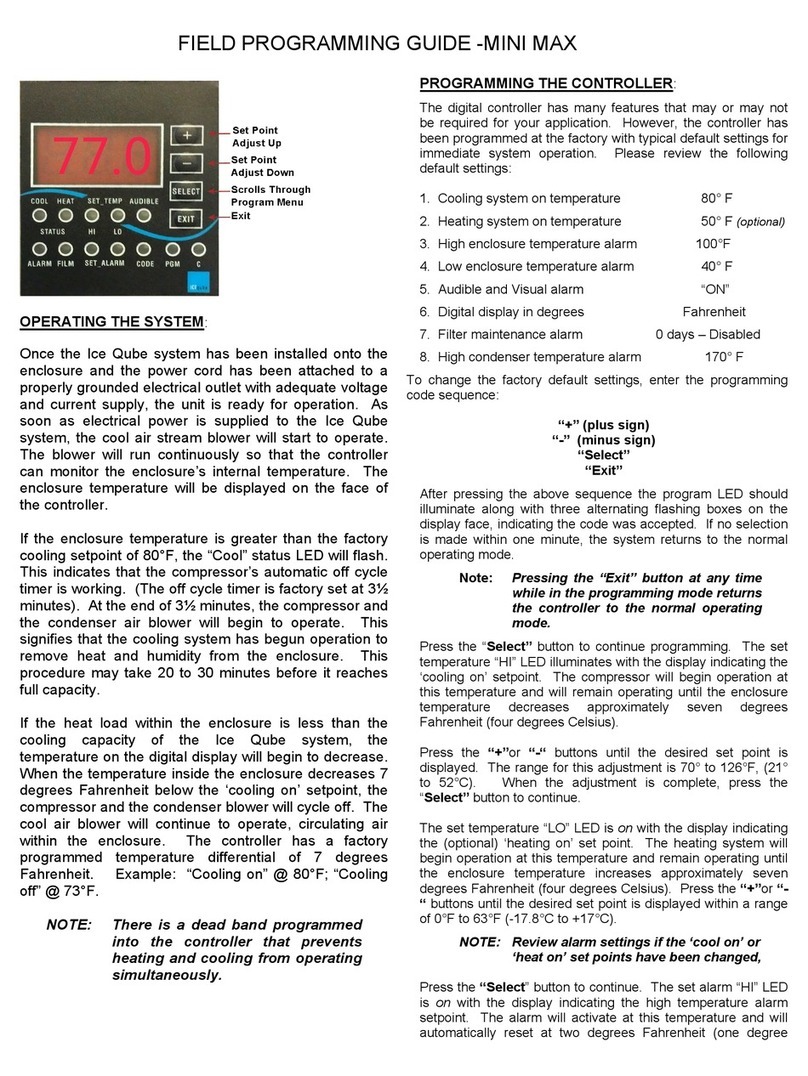
PROGRAMMING THE CONTROLLER:
The digital controller has many function settings that may or may not be required for your application. However, the controller
has been set at the factory with typical default settings for immediate system operation. Please review the following default
settings.
Cooling Start Temperature 80ºF (27°C)
Heating Start Temperature 50ºF (10°C)
High Temperature Alarm 100ºF (38°C)
Low Temperature Alarm 40ºF (4°C)
Full Speed Temperature 98ºF (37°C)
Visual Alarm “ON”
Audible Alarm “ON”
Default Temperature Unit Fahrenheit
User Pin code Setting “+” “–“ “Select” “Exit” (1,2,3,4)
Filter Maintenance Alarm 0 days-disabled
CommunicationAddress 1 (not used)
To change the controller settings, please follow the sequence below to enter the pin code 1234 into the program modification:
“+” 1
“-” 2
“Select” 3
“Exit” 4
Figure 2: Digital Tap Sensitive Controller
After entering the above sequence, three alternating flashing boxes should be shown on the display face, indicating the
code was accepted. If no selection is made within one minute, the system returns to the normal operating mode.
NOTE: If entering the PIN code fails the first time, please wait until the key icon disappears and then enter the pin code again.
Press “Exit” to go back to normal mode from the controller programming mode.
Press the “SELECT” button to continue programming. and icons indicate the 'cooling on' set point is shown on the
controller display. The cooling system will begin operation at this temperature and will remain operating until the enclosure
temperature decreases approximately seven degrees Fahrenheit (four degrees Celsius) below the cooling on set point.
Press the “+” or “-” button until the desired set point is displayed. The range for this adjustment is 70° to 126°F, (21° to
52°C).
Press the “SELECT” button to continue programming. When and is displayed on the screen, it indicates the 'heating
on' setting. The heating system will begin operation at this temperature and remain operating until the enclosure temperature
increases approximately seven degrees Fahrenheit (four degrees Celsius) above the 'heating on' set point. Press the “+”
or “-” until the desired set point is displayed within a range of -22°F to 68°F (-30°C to +20°C).
NOTE: Review alarm settings if the ‘cool on’ or ‘heat on’ set points have been changed.
Press “SELECT” to continue programming. and icons appearing on the screen indicate the setting for high
temperature alarm set point. The alarm will activate at this temperature and will automatically reset at two
degrees Fahrenheit (one degree Celsius) below this temperature. Press the “+” or “-” button to change the
alarm set point within a range of 7ºF (or 4ºC) above the 'cooling on' set point, to 140°F (60°C).

QD-ENG-68 Rev0 7/12/16 4
Press “SELECT” to continue the setting. and icons appear on the screen, indicating the setting for low
temperature alarm. The alarm will activate at this temperature and will automatically reset at two degrees Fahrenheit (or
one degree Celsius) above this temperature. Press the “+” or “-” button to change the alarm setpoint within a range of -
31ºF (-35ºC) to 7º F (4ºC) below the 'heating on' set point.
Press “SELECT” to continue the setting. When and appears on the screen, the display will show the temperature at
which all fans will be running at full speed. Press the “+” or “-“ key pads to change the high speed set point within a range
from the ‘cooling on set point’ to 72°F (30°C) above ‘cooling on set point’.
Press “SELECT” to enter the alarm function setting. The screen shows the current status of the alarm. When “off” is shown
on the screen, all the alarm functions will stop. Press “+” or “-” to change the alarm switches accordingly. If the “OFF” mode
is selected, no alarms will activate and the audible on/off select function is skipped.
Press “SELECT” to enter the audible alarm setting. When or is lit, “on” or “off” will appear accordingly on the LCD
screen to show the status of the audible alarm. Press “+” or “-” to toggle the mode as desired.
Press “SELECT” to enter the temperature unit setting. Press “+” or “-” to select the desired temperature unit of Fahrenheit
or Celsius.
Press “SELECT” to continue. The display shows “PIN”. If you need to set a new pin code, press “+” on the key pad.
When “0” shows on the screen, the controller is ready to accept the new pin code. Use the keys “+”, “-”, “SELECT” and
“EXIT” to reset a new 4-digit pin code. (The four keys can be set as pin code in any order). When the first key is pressed
on the key pad, the controller display shows -1-, indicating the first digit of the pin code has been entered. Numbers -2-, -
3-, and -4- are displayed sequentially after pressing the other keys. When the fourth-digit of the pin code is entered, the
controller will move on to the next step of the programming. If the fourth pin code is not entered within 60 seconds, the
system will log out automatically. The pin code setting fails and the system will continue to use the previous pin code.
*** CAUTION***
Always record the selection sequence (PIN code) and store in a secure place.
Press "SELECT” to continue. The and icons are displayed and the filter maintenance reminder setting is shown.
Press “+” or “-” to change the alarm setting. Its setting range is 0-180 days. Programming 0 days will disable the alarm.
NOTE: The required number of days to set this alarm will be determined by the ambient air conditions. The
filter alarm should be set to “0” to disable the filter alarm for systems that do not have a filter.
Press “SELECT” to enter the communication address setting. The LCD screen is will show the current communication
address. Press “+” or “-” to change the address value within range of 1-255. The factory setting of the communication
address is 1. This function is not available for certain models.
Programming of the controller is now complete. Press the “SELECT” button to review all of the settings. Press the
“EXIT” button to enter the selected settings and to return to the normal operating mode.
NOTE: If “EXIT: button is not pressed, any changes to the program will NOT be saved.
Recovering the Factory Settings
In order to recover the default factory settings in the controller, press 442213 under the normal operation condition. When
the LCD screen shows “---” for 3 seconds, the controller restarts. Then the controller parameters are set back to factory
default settings.

QD-ENG-68 Rev0 7/12/16 5
ALARM OPERATION:
1. The enclosure temperature is above or below the alarm set point:
The display flashes, + + or + + icons will also flash with the display and the audible alarm
sounds (if activated). The enclosure temperature must rise or fall by 2°F (1°C) before the alarm resets.
2. A fan failure is detected:
The controller in the Ice Qube TMS will test its fan speeds regularly. When a fan malfunctions or its speed is over 35%
of the set range, the controller will give a fan malfunction alarm, and the
icons + + “fan No.” will appear on the screen. The fan numbers “1” and “2” refer to internal circulating fans; “3”,
“4” and “5” refer to external circulating fans; and “6” refers to the hydrogen fan. The hydrogen fan option is not available
for TEC Series.
3. The filter day timer has expired:
The display flashes showing , and the audible alarm sounds (if activated). The filter alarm can be cleared by
pressing “EXIT”. Should be disabled for these models.
4. A sensor malfunction has been detected:
+ + +“---” indicates the evaporator sensor malfunction.
Table of contents
Other Ice Qube Controllers manuals