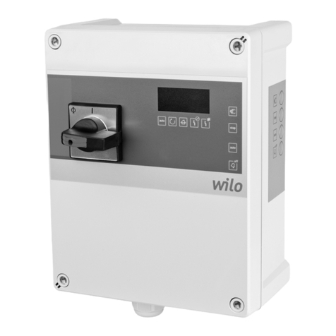
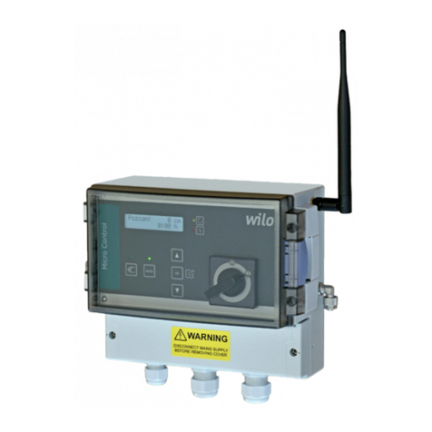
Wilo SC-HVAC SC User manual

Wilo-Control SC-HVAC (SC, SC-FC, SCe)
Pioneering for You
2 542 066-Ed.01 / 2014-02-Wilo
de Einbau- und Betriebsanleitung
en Installation and operating instructions
fr Notice de montage et de mise en service
nl Inbouw- en bedieningsvoorschriften


Fig. 1a:
1
2
4
3
Fig. 1b:
1
2
4
5
3

Fig. 1c:
1
2
4
5
3
Fig. 1d:
1
1
2
4
5
3

Fig. 1e:
1
2
4
6
7
8
5
3
Fig. 1f:
1
1
2
4
6
7
8
3
5

Fig. 1g:
1
1
2
4
6
7
8
3
5
Fig. 2:
123
4
X
Q/m3/h
Fig. 3:
23
X
Q/m3/h
Fig. 4a:
123
4
X
Q/m3/h
Fig. 4b:
123
4
X
Q/m3/h

Fig. 4c:
123
4
X
Q/m3/h
Fig. 5:
Fig. 6:
PL
off
PL
on
H
set
∆p-c
∆p/m
Q/m
3
/h
Fig. 7:
PL
off
PL
on
H
min
Q
max1
H
min
≥
0,4 · H
set
H
set
∆p-v
∆p/m
Q/m3/h
Fig. 8:
PL
off
PL
on
p
set
p-c
p/ bar
Q/m
3
/h
Fig. 9:
PL
off
PL
on
∆T
set
∆T-c
Q/m3/h
∆T/K

Fig. 10:
f
max
fall raise
T
max
T
min
f
min1
n = f (Tx)
Tx/°C
f/Hz
Fig. 11:
f
max
204
f
min1
n = f (AI)
Analog IN/mA
f/Hz

English
Installation and operating instructions Wilo-SC/SCe-HVAC 45
1 General ................................................................................................................................................. 46
2 Safety ................................................................................................................................................... 46
2.1 Symbols and signal words in the operating instructions ................................................................................ 46
2.2 Personnel qualifications ..................................................................................................................................... 47
2.3 Danger in the event of non-observance of the safety instructions .............................................................. 47
2.4 Safety consciousness on the job ....................................................................................................................... 47
2.5 Safety instructions for the operator ................................................................................................................. 47
2.6 Safety instructions for installation and maintenance work ........................................................................... 48
2.7 Unauthorised modification and manufacture of spare parts ......................................................................... 48
2.8 Improper use ........................................................................................................................................................ 48
3 Transport and interim storage ........................................................................................................... 48
4 Intended use ........................................................................................................................................ 48
5 Product information ........................................................................................................................... 49
5.1 Type key ............................................................................................................................................................... 49
5.2 Technical data ...................................................................................................................................................... 49
5.3 Scope of delivery ................................................................................................................................................. 49
5.4 Accessories .......................................................................................................................................................... 49
6 Description and function .................................................................................................................... 50
6.1 Description of the product ................................................................................................................................. 50
6.1.1 Function description ........................................................................................................................................... 50
6.1.2 Set-up of the control device .............................................................................................................................. 50
6.2 Function and operation ....................................................................................................................................... 51
6.2.1 Operating modes of the switchgear .................................................................................................................. 51
6.2.2 Control modes ..................................................................................................................................................... 54
6.2.3 Motor protection ................................................................................................................................................. 55
6.2.4 Operation of the switchgear .............................................................................................................................. 56
6.2.5 Menu structure .................................................................................................................................................... 62
6.2.6 Operation levels .................................................................................................................................................. 78
7 Installation and electrical connection .............................................................................................. 78
7.1 Installation ........................................................................................................................................................... 78
7.2 Electrical connection .......................................................................................................................................... 79
7.2.1 Mains connection ................................................................................................................................................ 79
8 Commissioning .................................................................................................................................... 84
8.1 Factory setting .................................................................................................................................................... 84
8.2 Checking the motor direction of rotation ........................................................................................................ 84
8.3 Adjusting the motor protection ......................................................................................................................... 85
8.4 Signal transmitters and optional modules ........................................................................................................ 85
9 Maintenance ........................................................................................................................................ 85
10 Faults, causes and remedies .............................................................................................................. 85
10.1 Fault display and acknowledgement ................................................................................................................. 85
10.2 History memory for the faults ........................................................................................................................... 86
11 Spare parts ........................................................................................................................................... 87
12 Disposal ................................................................................................................................................ 87

English
46 WILO SE 02/2014
Installation and operating instructions
1General
About this document The language of the original operating instructions is German. All
other languages of these instructions are translations of the original
operating instructions.
These installation and operating instructions are an integral part of
the product. They must be kept readily available at the place where
the product is installed. Strict adherence to these instructions is a
precondition for the proper use and correct operation of the product.
These installation and operating instructions correspond to the rele-
vant version of the product and the underlying safety standards valid
at the time of going to print.
EC declaration of conformity:
A copy of the EC declaration of conformity is a component of these
operating instructions.
If a technical modification is made on the designs named there with-
out our agreement or the declarations made in the installation and
operating instructions on product/personnel safety are not observed,
this declaration loses its validity.
2Safety These operating instructions contain basic information which must
be adhered to during installation, operation and maintenance. For this
reason, these operating instructions must, without fail, be read by the
service technician and the responsible specialist/operator before
installation and commissioning.
It is not only the general safety instructions listed under the main
point “safety” that must be adhered to but also the special safety
instructions with danger symbols included under the following main
points.
2.1 Symbols and signal words in the
operating instructions
Symbols General danger symbol
Danger due to electrical voltage
NOTE
Signal words DANGER!
Acutely dangerous situation.
Non-observance results in death or the most serious of injuries.
WARNING!
The user can suffer (serious) injuries. ’Warning’ implies that (seri-
ous) injury to persons is probable if this information is disregarded.
CAUTION!
There is a risk of damaging the product/unit. ’Caution’ implies that
damage to the product is likely if this information is disregarded.
NOTE:
Useful information on handling the product. It draws attention to
possible problems.

English
Installation and operating instructions Wilo-SC/SCe-HVAC 47
Information that appears directly on the product, such as:
• Direction of rotation arrow
•Connectionmarks
• Rating plate
• Warning stickers
must be strictly complied with and kept in legible condition.
2.2 Personnel qualifications The installation, operating and maintenance personnel must have the
appropriate qualifications for this work. Area of responsibility, terms
of reference and monitoring of the personnel are to be ensured by the
operator. If the personnel are not in possession of the necessary
knowledge, they are to be trained and instructed. This can be accom-
plished if necessary by the manufacturer of the product at the request
of the operator.
2.3 Danger in the event of non-
observance of the safety
instructions
Non-observance of the safety instructions can result in risk of injury
to persons and damage to the environment and the product/unit.
Non-observance of the safety instructions results in the loss of any
claims to damages.
In detail, non-observance can, for example, result in the following
risks:
• Danger to persons from electrical, mechanical and bacteriological
influences
• Damage to the environment due to leakage of hazardous materials
• Property damage
• Failure of important product/unit functions
• Failure of required maintenance and repair procedures
2.4 Safety consciousness on the job The safety instructions included in these installation and operating
instructions, the existing national regulations for accident prevention
together with any internal working, operating and safety regulations
of the operator are to be complied with.
2.5 Safety instructions for the operator This appliance is not intended for use by persons (including children)
with reduced physical, sensory or mental capabilities, or lack of expe-
rience and knowledge, unless they have been given supervision or
instruction concerning use of the appliance by a person responsible
for their safety.
Children should be supervised to ensure that they donot play with the
appliance.
• If hot or cold components on the product/the unit lead to hazards,
local measures must be taken to guard them against touching.
• Guards protecting against touching moving components (such as the
coupling) must not be removed whilst the product is in operation.
• Leakages (e.g. from the shaft seals) of hazardous fluids (which are
explosive, toxic or hot) must be led away so that no danger to persons
or to the environment arises. National statutory provisions are to be
complied with.
• Highly flammable materials are always to be kept at a safe distance
from the product.
• Danger from electrical current must be eliminated. Local directives or
general directives [e.g. IEC, VDE etc.] and instructions from local
energy supply companies must be adhered to.

English
48 WILO SE 02/2014
2.6 Safety instructions for installation
and maintenance work
The operator must ensure that all installation and maintenance work
is carried out by authorised and qualified personnel, who are suffi-
ciently informed from their own detailed study of the operating
instructions.
Work on the product/unit must only be carried out when at a stand-
still. It is mandatory that the procedure described in the installation
and operating instructions for shutting down the product/unit be
complied with.
Immediately on conclusion of the work, all safety and protective
devices must be put back in position and/or recommissioned.
2.7 Unauthorised modification and
manufacture of spare parts
Unauthorised modification and manufacture of spare parts will impair
the safety of the product/personnel and will make void the manufac-
turer’s declarations regarding safety.
Modifications to the product are only permissible after consultation
with the manufacturer. Original spare parts and accessories author-
ised by the manufacturer ensure safety. The use of other parts will
absolve us of liability for consequential events.
2.8 Improper use The operating safety of the supplied product is only guaranteed for
conventional use in accordance with Section 4 of the operating
instructions. The limit values must on no account fall under or exceed
those specified in the catalogue/data sheet.
3 Transport and interim storage Immediately after receiving the product: Check the product for trans-
port damage. If transport damage is detected, the necessary steps
involving the carrier must be taken within the specified period.
CAUTION! Risk of property damage!
Incorrect transport and interim storage can cause damage to the
product.
• The switchgear is to be protected against moisture and mechanical
damage.
• The switchgear must not be exposed to temperatures outside the
range between -10°C and +50°C.
4 Intended use
Purpose The SC/SCe switchgear is used for automatic, convenient control of
single-pump and multi-pump systems.
Fields of application The field of application includes heating, ventilation and air-condi-
tioning systems in residential buildings, hotels, hospitals and admin-
istrative and industrial buildings.
When used in conjunction with suitable signal transmitters, the
pumps offer low-noise and energy-saving operation. The perfor-
mance of the pumps is adapted to the constantly changing require-
ments in the heating/water-supply system.
CAUTION! Risk of property damage!
Incorrect use/handling can lead to damage to the product.
• Intended use also includes compliance with these instructions.
• Any other use is considered to be outside the intended use.

English
Installation and operating instructions Wilo-SC/SCe-HVAC 49
5 Product information
5.1 Type key The type key consists of the following elements:
Tab. 1 – Type key
5.2 Technical data
Tab. 2 – Technical data
Please provide all the information on the rating plate when ordering
spare parts.
5.3 Scope of delivery • SC/SCe-HVAC switchgear
• Wiring diagram
• Installation and operating instructions for SC/SCe-HVAC
• Installation and operating instructions for frequency converter (only
for SC ... FC version)
• Test report acc. to EN 60204-1
5.4 Accessories Accessories must be ordered separately:
Tab. 3 – Accessories
Example: SC-HVAC 4x3.0 DOL FC WM
SC
SCe
Smart Controller for pumps with fixed speed
Smart Controller for electronic pumps
HVAC Application in heating, ventilation and air-condi-
tioning systems
4x Number of pumps
3.0 Max. rated motor power P2[kW]
DOL
SD
Direct online (direct start)
Star-delta starting
FC With frequency converter
WM
BM
Wall mounted
Base mounted
Property Value Remarks
Mains supply voltage 3~400 V (L1, L2, L3, PE)
Frequency 50/60 Hz
Control voltage 24 V DC, 230 V AC
Max. current consumption See rating plate
Protection class IP 54
Max. fuse protection on mains side See wiring diagram
Max. permissible ambient temperature 0 to +40°C
Electrical safety Pollution degree II
Accessory Description
Signal board Relay output module for outputting individual run signals and fault signals
LON communication module Bus communication module for “LON” networks
BACnet communication Connection to BACnet MSTP (RS485)
ModBus RTU communication Connection to ModBus RTU (RS485)

English
50 WILO SE 02/2014
6Descriptionandfunction For a description of the product, see also Fig. 1a to Fig. 1g.
6.1 Description of the product
6.1.1 Function description The Smart control system, controlled by a microcontroller, is used to
control pump systems with up to 4 single pumps. The control variable
of a system is measured with corresponding signal transmitters and
controlled load-sensitively.
In the SC version, all pumps are fixed speed pumps – the control is a
2-point control. Non-controlled peak-load pumps are switched on
and off automatically depending on the load requirement.
In the SC-FC version, the controller acts on a frequency converter,
which in turn influences the speed of the base-load pump. A modifi-
cation of the speed changes the volume flow and thus the power out-
put of the pump system. Non-controlled peak-load pumps are
switched on and off automatically depending on the load require-
ment.
In the SCe version, each pump has an (integrated) frequency con-
verter, with only the base-load pump undertaking the speed control.
6.1.2 Set-up of the control device The set-up of the control device is dependent on the performance of
the pumps that are tobe connected,and the version(SC, SC-FC, SCe),
see
Fig. 1a: SCe WM
Fig. 1b: SC direct starting WM
Fig. 1c: SC star-delta starting WM
Fig. 1d: SC star-delta starting BM
Fig. 1e: SC-FC direct starting WM
Fig. 1f: SC-FC direct starting BM
Fig. 1g: SC-FC star-delta starting BM
It consists of the following main components:
•Main switch:
Switches the switchgear on/off (item 1).
•Human-machine interface (HMI):
LCD for displaying operating data (see menus), LEDs for displaying the
operating status (operation/fault), operating knob for menu selection
and parameter input (item 2).
•Base board:
Printed circuit board with microcontroller; version corresponding to
device version (SC/SC-FC or SCe) (item 3).
•Fuse protection of drives and the frequency converter:
Fuse protection of the pump motors and the frequency converter.
In DOL version devices: Motor protection switch.
In the SCe version: Circuit breaker to protect the pump mains power
cable (item 4).
•Contactors/contactor combinations:
Contactors for switching on the pumps. In SD version devices, includ-
ing the thermal tripping devices for excess current protection (set
value: 0.58 x IN) and the time relay for the star-delta switching
(item 5).
•Frequency converter:
Frequency converter for load-sensitive speed control of the base-
load pump – only in the SC-FC version (item 6).
•Motor filter:
Filter for ensuring a sinusoidal motor voltage and for suppressing
voltage peaks – only in the SC-FC version (item 7).
•EMC filter:
Filter for suppressing EMC interference on mains side – only in the
SC-FC version up to 7.5 kW (item 8).

English
Installation and operating instructions Wilo-SC/SCe-HVAC 51
6.2 Function and operation DANGER! Risk of fatal injury!
When working on the open switchgear, there’s a danger of electric
shock from touching the live components.
• The work must be carried out only by qualified personnel!
• Adhere to regulations for accident prevention!
NOTE:
After connecting the switchgear to the supply voltage, as well as after
every mains interruption, the switchgear returns to the operating
mode set before the power interruption.
6.2.1 Operating modes of the switchgear
Normal operation of SC switchgear
with frequency converter (FC)
(see Fig. 2)
An electronic signal transmitter (measurement range to be set in
menu 5.2.1.0) supplies the control variable actual value as a 4...20 mA
current signal. Then the controller holds the current control variable
constant by comparing the setpoint and the actual value (for setting
of the reference setpoint (see Fig. 2, item 1), see menu 1.2.1.1). If
there is no “external off” signal and no fault, at least the base-load
pump runs at minimum speed. If the power requirement rises, the
speed of the base-load pump is first increased. If the power require-
ment cannot be met by this pump, the control system switches on a
peak-load pump and, if the requirement increases further, other
peak-load pumps (activation threshold: see Fig. 2, item 2; can be set
individually for each pump; menu 1.2.2.3/5/7). The peak-load pumps
run at constant speed; the speed of the base-load pump is controlled
to the setpoint in each case (see Fig. 2, item 4).
If the requirement drops until the controlling pump is working in its
lower performance range and no peak-load pump is required any
longer in order to meet the requirement, then the peak-load pump
switches off (deactivation threshold: see Fig. 2, item 3; can be set
individually for each pump; menu 1.2.2.4/6/8).
Delay times can be set in the menus 1.2.5.2 and 1.2.5.3 for activation
and deactivation of the peak-load pump.
If the frequency converter has a fault, the switchgear behaves like
switchgear without a frequency converter (see next section).
Normal operation of SC switchgear
without frequency converter
(see Fig. 3)
An electronic signal transmitter (measurement range to be set in
menu 5.2.1.0) supplies the control variable actual value as a 4...20 mA
current signal. Because there is no possibility for load-sensitive speed
adaptation of the base-load pump, the system works as a two-point
controller and keeps the control variable in the range between the
activation and deactivation thresholds (menus 1.2.2.3 to 1.2.2.8).
These must be set inrelation to the reference setpoint (menu 1.2.1.1).
If there is no “external off” signal and no fault, at least the base-load
pump runs. If the power requirement cannot be met by this pump, the
control system switches on a peak-load pump and, if the requirement
increases further, other peak-load pumps (activation threshold: see
Fig. 3, item 2; can be set individually for each pump; menu 1.2.2.3/5/7).
If the requirement drops until no peak-load pump is required any
longer in order to meet the requirement, then the peak-load pump
switches off (deactivation threshold: see Fig. 3, item 3; can be set
individually for each pump; menu 1.2.2.4/6/8).
Delay times can be set in the menus 1.2.5.2 and 1.2.5.3 for activation
and deactivation of the peak-load pump.
Normal operation of SCe switchgear
(see Fig. 3)
An electronic signal transmitter (measurement range to be set in
menu 5.2.1.0) supplies the control variable actual value as a 4...20 mA
current signal. Then the controller holds the control variable constant
by comparing the setpoint and the actual value (for setting of the ref-
erence setpoint (see Fig. 3, item 1), see menu 1.2.1.1). If there is no

English
52 WILO SE 02/2014
“external off” signal and no fault, at least the base-load pump runs at
minimum speed (Fig. 4a). If the power requirement can no longer be
met by this pump at the speed that can be set in menu 1.2.3.1,
another pump starts when the reference setpoint is undershot (see
Fig. 3, item 1) and takes over the speed control (Fig. 4b). The previous
base-load pump continues to run at max. speed as a peak-load pump.
This procedure is repeated with increasing load until the maximum
number of pumps is reached (here: 3 pumps – see Fig. 4c).
If the requirement drops, then the controlling pump is switched off
when the speed that can be set in menu 1.2.3.2 is reached and the
reference setpoint is exceeded at the same time; then, a former peak-
load pump takes over control.
Delay times can be set in the menus 1.2.5.2 and 1.2.5.3 for activation
and deactivation of the peak-load pump.
Pump cycling Various mechanisms of pump cycling are applied optionally in order to
ensure that the loads on all pumps are as uniform as possible and to
balance the running times of the pumps.
The base-load pump is cycled on each requirement (after deactiva-
tion of all pumps).
Furthermore, a cycling of the base-load pump can also be activated
(menu 5.6.1.0). The running time between 2 cycling procedures can
be set in menu 5.6.2.0.
Standby pump One pump can be defined as the standby pump. When this operating
mode is activated, this pump is not activated in normal operation. It is
switched on only if a pump fails due to a fault. However, the standby
pump is subject to standstill monitoring and is included in the test run.
Service life optimisation ensures that every pump becomes a standby
pump once.
This function is preset at the factory and can be changed only by Wilo
customer service.
Pump test run A cyclic test run of the pumps can be activated in order to avoid
lengthy standstill periods (menu 5.7.1.0). The time between two test
runs can be defined in menu 5.7.2.0 for this purpose. In the SCe and
SC...FC versions, the speed of the pump (during the test run) can be
set (menu 5.7.3.0).
A test run only happens when the system is at standstill. A test run
does not happen when the switchgear is in “external off” status.
Low water
(only for control mode Δp-c)
A low-water signal can be fed to the control system via a normally
closed contact by means of the signal from a suction-side pressure
switch or break tank float switch. The pumps are switched off after a
delay time that can be set in menu 1.2.5.4 has expired. If the signal
input is closed again within the delay time, this does not lead to deac-
tivation.
The system restart after a deactivation due to low water is performed
automatically after the signal input closes (delay time acc. to menu
1.2.5.5).
The fault signal is reset automaticallyafter the restart. However, it can
be read out from the history memory.
Monitoring of maximum and mini-
mum pressure (only for control mode
Δp-c)
The limit values for safe system operation can be set in menu 5.4.0.0.
Exceeding the maximum pressure (menu 5.4.1.0) leads to delayed
(menu 5.4.4.0) deactivation of all pumps. The collective fault signal is
activated.
Normal operation is enabled again after the pressure has dropped
below the activation threshold.

English
Installation and operating instructions Wilo-SC/SCe-HVAC 53
In menu 5.4.2.0, it is possible to set the pressure threshold of the min-
imum pressure monitoring, and in menu 5.4.5.0, the delay time. The
behaviour of the switchgear when this pressure threshold is under-
shot can be selected in menu 5.4.3.0 (deactivation of all pumps or
continued operation). The collective fault signal is activated in all
cases.
External off It is possible to deactivate the control device externally using a nor-
mally closed contact. This function takes priority; all pumps running in
automatic mode are switched off.
The pumps can be started in manual mode. The frost protection func-
tion is active.
Operation in the event of a sensor
fault
In the event of a sensor fault (e.g. wire break), the behaviour of the
switchgear can be defined in menu 5.2.3.0. The system is either
switched off or continues to run with a pump. In the SCe and SC...FC
versions, the speed of this pump can be set in menu 5.2.4.0.
Operating mode of the pumps The operating mode of the pumps can be selected in menus 3.2.1.1,
3.2.2.1, 3.2.3.1 and 3.2.4.1 (hand, off, auto). In the SCe version, the
speed in “hand” operating mode can be set (menus 3.2.1.2, 3.2.2.2,
3.2.3.2 and 3.2.4.2).
Setpoint changeover The control system can work with two different setpoints. They are
set in menus 1.2.1.1 and 1.2.1.2.
Setpoint 1 is the reference setpoint. A changeover to setpoint 2 is
performed by closing the external digital input (acc. to wiring dia-
gram).
If setpoint 2 is set to 0, all pumps are switched off and the frost pro-
tection function is activated.
Remote setpoint adjustment Using the corresponding terminals (in accordance with the wiring dia-
gram), remote adjustment of the setpoint is possible using an ana-
logue current signal (4-20 mA). This function can be activated in
menu 5.3.1.0.
The input signal is always in relation to the sensor measuring range
(e.g. DDG 40: 20 mA corresponds to 40 m (water column)).
In control mode T-c, 4-10 mA corresponds to 0-150 K.
If the external setpoint is 0, all pumps are switched off and the frost
protection function is activated.
Function of the collective run signal
(SBM)
The desired function of the SBM can be set in menu 5.5.1.0. In this
case, it is possible to select between “Ready” (switchgear is ready for
operation) and “Run” (at least one pump is running).
Logic reversal of the collective fault
signal (SSM)
The desired logic of the SSM can be set in menu 5.5.2.0. In this case, it
is possible to select between negative logic (falling edge in case of a
fault = “fall”) or positive logic (rising edge in case of a fault = “raise”).
Frost protection (not for control
mode Δp-c)
A frost protection signal can be fed to the control system via a nor-
mally closed contact by means of the signal from a frost protection
thermostat. If the signal input is opened, a pump is activated at min-
imum speed with a delay, and the collective fault signal is activated.
After the normally closed contact closes, the system returns to the
specified automatic mode. The fault signal is reset automatically, but
can be read out from the history memory.
Frost protection operation is possible only if the system is switched
off by setpoint 2, analogue external setpoint or external OFF.

English
54 WILO SE 02/2014
Fault-actuated switchover of multi-
pump system
SC switchgear with frequency converter (FC):
If the base-load pump has a fault, it is switched off and another pump
is switched onto the frequency converter. If the frequency converter
has a fault, the switchgear works like an SC switchgear without fre-
quency converter.
SC switchgear without frequency converter:
If the base-load pump has a fault, it is switched off and one of the
peak-load pumps is managed by the control system as a base-load
pump.
SCe switchgear:
If the base-load pump has a fault, it is switched off and another pump
takes over the control function.
A fault of a peak-load pump always leads to its deactivation and to
the activation of another peak-load pump (possibly also the standby
pump).
6.2.2 Control modes The basic control mode of the system can be preselected in menus
1.1.1.0 to 1.1.1.8.
An electronic signal transmitter (measurement range to be set in
menu 5.2.1.0) supplies the control variable actual value, e.g. as a
4...20 mA current signal. For the devices with temperature sensor
inputs, the resistance change of Pt100 or Pt1000 sensors is detected
(depending on the jumper setting; see Fig. 5).
The following control modes can be selected:
p-c (constant differential pressure – see Fig. 6)
The differential pressure (between two system points) is held con-
stant in accordance with the setpoint under changing load conditions
(volume flow).
Multi-pump operation is possible.
p-v (variable differential pressure – see Fig. 7) (only SCe/SC…FC)
The control setpoint of the exclusively running base-load pump is
adjusted and corrected as a function of the volume flow between
Hmin (menu 1.2.1.3) and setpoint (setpoint ≥Hmin ≥0.4 x setpoint).
Furthermore, the zero-delivery head (H0) of the pump must be input
(menu 1.2.1.1).
After load-sensitive cut-in of one or more peak-load pumps, the sys-
tem operates in the p-c mode.
Multi-pump operation is possible. External analogue setpoint specifi-
cation is possible.
p-c (constant absolute pressure – see Fig. 8)
The output pressure of the system is held constant in accordance with
the setpoint under changing load conditions (volume flow).
Multi-pump operation is possible.
T-c (constant differential temperature – see Fig. 9)
The differential temperature (between two system points; feed/
return) is held constant in accordance with the setpoint under chang-
ing load conditions (volume flow).
Multi-pump operation is possible.

English
Installation and operating instructions Wilo-SC/SCe-HVAC 55
n=f(xT) (speed-controller – dependent on temperature –
see Fig. 10)
The speed of the base-load pump is set in dependence on the input
temperature (select the control mode in accordance with the desired
temperature input). You can choose between rising and falling
dependence on the control input (menu 1.2.4.4).
The speed of the base-load pump is set between fmin and fmax
(1.2.6.1 and 1.2.6.2) and Tmin and Tmax (1.2.1.1 and 1.2.1.2).
Multi-pump operation is not possible.
n=f(AI) (manual control mode – see Fig. 11)
Using the corresponding terminals (in accordance with the wiring dia-
gram), remote adjustment of the speed of the base-load pump is pos-
sible using an analogue current signal (4-20 mA).
The speed of the base-load pump is set between fmin and fmax (1.2.6.1
and 1.2.6.2) (4 mA corresponds to fmin; 20 mA corresponds to fmax).
Multi-pump operation is not possible.
6.2.3 Motor protection Excess temperature protection
Motors with WSK (thermal winding contact) signal an excess winding
temperature to the control device by opening a bimetal strip contact.
The WSK is connected according to the wiring diagram.
Faults of motors that are equipped with a temperature-dependent
resistor (PTC) for excess temperature protection can be detected
using optional evaluation relays.
Excess current protection
Direct-starting motors are protected by motor protection switches
with thermal and electromagnetic tripping devices. The trigger cur-
rent (Inom) must be set directly at the motor protection switch.
Motors with Y-∆starting are protected by thermal overload relays.
These are installed directly on the motor contactors. The trigger cur-
rent must be set and is 0.58 x Inom with the Y-∆starting of the pumps
used.
All motor protection devices protect the motor during operation with
the frequency converter or in mains operation. Pump faults which
reach the switchgear result in deactivation of the corresponding
pump and activation of the SSM. After the cause of the fault has been
rectified, it is necessary to acknowledge the fault.
The motor protection is also active in manual mode and leadsto deac-
tivation of the corresponding pump.
In the SCe version, the pump motors protect themselves by mecha-
nisms integrated in the frequency converters. The error messages
from the frequency converters are handled in the switchgear as
described above. Acknowledgement is not required after the errors
have been corrected.
This manual suits for next models
2
Table of contents
Other Wilo Controllers manuals

Wilo
Wilo Wilo-Control SC-Fire Electric A2P User manual

Wilo
Wilo AlarmControl 1 User manual

Wilo
Wilo Stratos Demo User manual

Wilo
Wilo Control MS-L User manual

Wilo
Wilo fluidcontrol ek User manual

Wilo
Wilo Control EC-HVAC User manual

Wilo
Wilo SK 602N User manual

Wilo
Wilo Wilo-Control MS-L User manual

Wilo
Wilo ER 2 User manual

Wilo
Wilo HiControl 1 User manual