ICG IC5 User manual

MANUFACTURED BY:
Cy-Tech GmbH
Happurger Str. 86
90482 NUERNBERG | Germany
www.indoorcycling.com
Phone: +49(0)911 / 54 44 50
CAUTION!
READ ALL PRECAUTIONS AND INSTRUCTIONS IN THIS MANUAL BEFORE YOU START
USING THIS EQUIPMENT. PLEASE KEEP THIS MANUAL FOR FUTURE REFERENCE.
IMPROPER ASSEMBLY, USE OR MAINTENANCE CAN VOID THE WARRANTY TERMS.
ADDITIONAL LANGUAGES AVAILABLE FOR DOWNLOAD AT WWW.INDOORCYCLING.COM
Version 2.0 2021 IC-IC5B1-01 Copyright by Cy-Tech GmbH 2021 | www.indoorcycling.com
ENG
IC5
MODEL NO:IC-IC5B1-01

Version 2.0 2021 IC-IC5B1-01 Copyright by Cy-Tech GmbH 2021 | www.indoorcycling.com
ATTENTION
Warning labels on the bikes must be replaced by warning labels
in your language during the assembly process.
A
B
A
B

3
ENG
ATTENTION
To download the owners manual in
your language, visit the IC5 support
section at: www.teamicg.com
Um das Handbuch in Ihrer Sprache
herunterzuladen, besuchen Sie bitte
den IC5 Support Bereich auf unserer
Webseite unter www.teamicg.com
Pour télécharger le manuel d‘utilisation
dans votre langue, consultez la section
Assistance IC5 sur: www.teamicg.com
Per scaricare il manuale nella vostra
lingua, visitate la sezione del supporto
per IC5 su: www.teamicg.com
Ga om de gebruiksaanwijzing in
uw taal te downloaden naar het IC5
supportgedeelte onder:
www.teamicg.com
Para descargarse el manual de usuario
en su idioma, por favor acceda a la
sección de soporte técnico de la bici IC5
en: www.teamicg.com
Para transferir o manual de utilizador no
seu idioma, visite a secção„Suporte“ da
IC5 em: www.teamicg.com
Besøg IC5 supportafsnittet www.
teamicg.com for at downloade
brugermanualen på dit sprog
Lataa omistajan käsikirja omalla
kielelläsi IC5-ohjeosiosta sivustolta:
www.teamicg.com
Du kan laste ned bruksanvisningen
på ditt eget språk ved å gå til IC5
støttesiden på: www.teamicg.com
Du kan hämta bruksanvisningen på ditt
språk under IC5-support på
www.teamicg.com
Aby pobrać podręcznik użytkowania w
swoim języku, należy wejść na zakładkę
IC5 support na stronie:
www.teamicg.com
Kullanıcı kılavuzunu kendi dilinizde
indirmek için www.teamicg.com
sayfasının IC5 deste bölümünü ziyaret
edebilirsiniz
在IC5的客户服务网站,您可以下载
各种语言的用户手册
www.teamicg.com
オーナーズマニュアルの各言語版
は、以下サイトの IC5 サポートペー
ジからダウンロードいただけます。
www.teamicg.com
IC5 지원 센터(www.teamicg.com)
에서 해당 언어 버전의 사용설명서를
다운로드할 수 있습니다..
EN
DE
FR
IT
NL
ES
PT
DK
FI
NO
SE
PL
TR
CN
JP
KR

Version 2.0 2021 IC-IC5B1-01 Copyright by Cy-Tech GmbH 2021 | www.indoorcycling.com
TECHNICAL SPECIFICATIONS:
The IC5 Bike is, according to EN ISO 20957-1 and EN ISO 20957-10, a Class S product for
use in a controlled environment such as sports or tness facilities
under the supervision of a trainer.
TABLE OF CONTENTS
IMPORTANT PRECAUTIONS P.5
GETTING STARTED P.6
HOW TO ASSEMBLE THE INDOOR CYCLE P.7-13
INSTALLATION AND SETUP P.14
INSTALLATION AND DISPOSAL OF BATTERIES P.15
HOW TO ADJUST THE INDOOR CYCLE P.16-18
HOW TO OPERATE THE INDOOR CYCLE P.19-21
PREVENTIVE MAINTENANCE P.22-25
MAINTENANCE ACTIVITY AND REQUIRED SCHEDULE P.26-27
SPARE PARTS P.28
WARRANTY P.29
WARNING!
Electronic components satisfy the EMV Directive 2014/53/EU, EMV Directive 99/519/EC,
and DIN EN 60335-1:2012/A14:2019 for electrical safety.
The declaration of Conformity can be viewed at www.indoorcycling.com
WEIGHT OF BIKE: 51 KG
MAX USER WEIGHT: 150 KG
USER HEIGHT: SUITABLE FOR USERS BETWEEN APPROX. 155 AND 215 CM
REQUIRED FOOT PRINT: APPROX. 132 X 52 CM
MAX SADDLE & HANDLEBAR HEIGHT: APPROX. 120 CM

5
ENG
1. It is the responsibility of the owner to ensure that
all users are informed of all warnings and precautions
for proper use, and are only authorized to use the
bike independently after being successfully briefed
by a qualied trainer or instructor.
2. Do not operate the bike until it has been properly
assembled and inspected as described in this manual.
3. Keep the indoor cycle indoors, away from moisture
and dust. Do not place the indoor cycle outdoors in
a garage or covered patio or near water or pools.
Operating temperature of the Indoor Cycle has to
be between 15°C~ 40°C Celsius (59°~104°F) at max.
humidity of 65%.
4. Always place the bike on a stable, level surface.
If the bike is to be placed on a hardwood oor or
carpet, it is recommended to place a oor mat
beneath the bike, to protect the oor
from becoming damaged.
5. The level of safety of the Indoor Bike can only
be guaranteed if it is regularly checked for possible
damage as well as wear and tear (e.g. xing
points, E-Brake, Pedals, toe straps, etc.). Consult an
authorized service provider or the manufacturer
direct to ensure the regular inspections are properly
carried out.
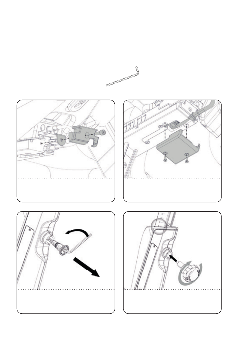
6. Carry out all maintenance, care and service
procedures as described in this manual on a regular
basis. Defective parts must be replaced immediately,
and the device must not be used until the repairs
have been carried out.
Only use original parts from the manufacturer.
Repairs must only be carried out by manufacturer
authorized service technicians.
7. Unsupervised children should be kept away from
the training device at all times.
8. WARNING: The training equipment can be used
by children aged from 14 years and above and
persons with lack of experience and knowledge if
they have been given supervision or instruction
concerning use of the appliance in a safe way and
understand the hazards involved. Persons with
reduced physical, sensory or mental capabilities
are prohibited from using the training equipment.
Children shall not play with the training equipment.
Cleaning and user maintenance shall not be made
by children without supervision.
9. The indoor cycle must not be used by persons
exceeding weight of 330 lbs/150 kg.
10. Always wear appropriate tight-tting cycling
or athletic attire and sturdy shoes, preferably
cycling shoes, while operating the bike. Unfastened
shoelaces may become caught in the drive system
and lead to injury.
11. The bike does not have an independently-moving
ywheel. The pedals will continue to move with the
ywheel until the ywheel stops. The movement can
only be stopped by using the emergency brake or
by reducing the pedaling frequency in a controlled
manner. Always ride with resistance load to ensure
that your pedaling motion is controlled. Do not
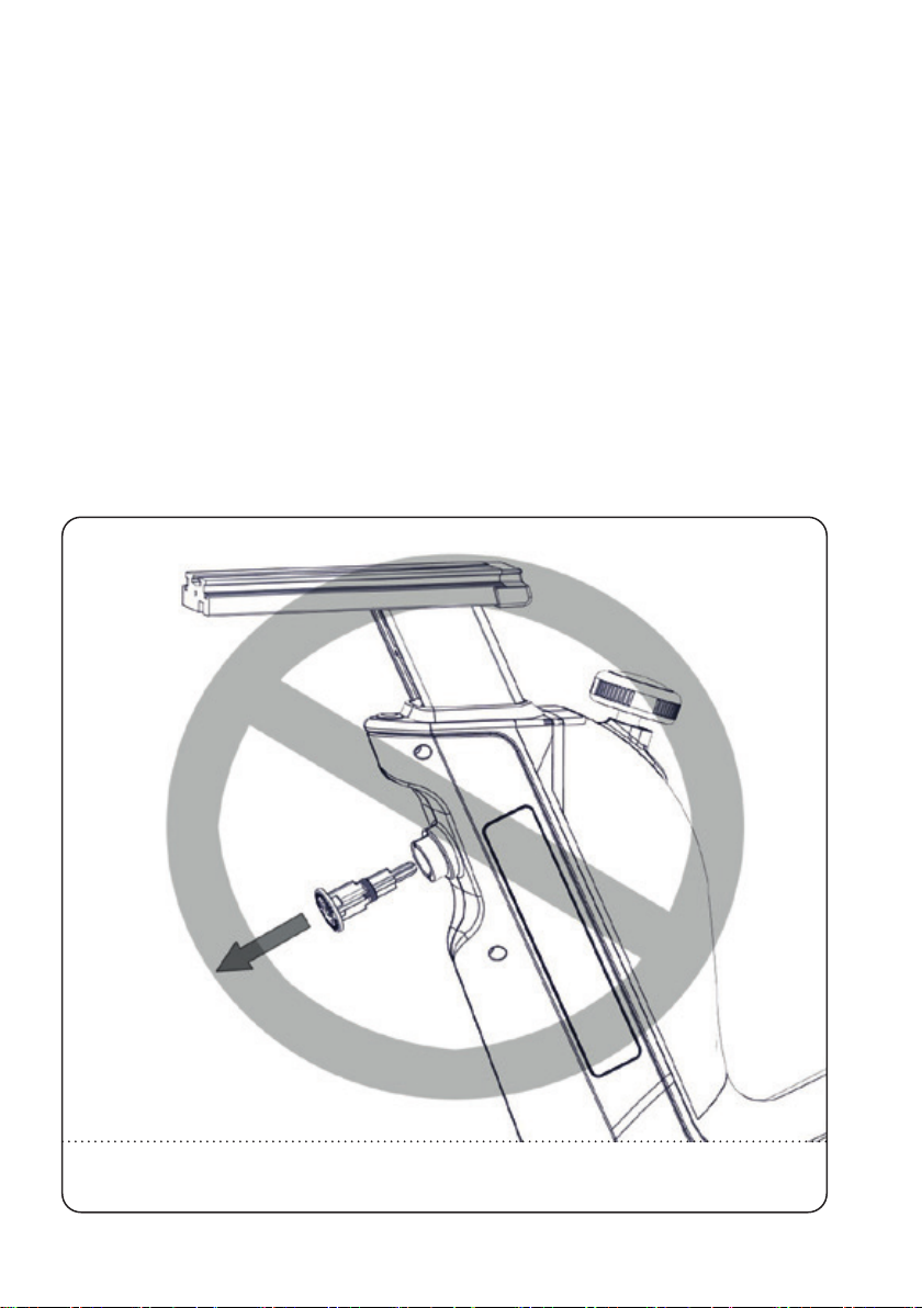
adjust handlebar or saddle during workout.
Do not pedal backwards.
12. If you feel pain or dizziness while exercising, stop
immediately. It is recommended that you consult
a doctor if the pain does not subside for an
extended period of time.
13. All data shown on the display, especially
the Watt values generated by the integrated
power sensor serve merely as information
and to help guide training. Only exercise
within your physical limitations.
IMPORTANT
PRECAUTIONS
WARNING!
To reduce the risk of serious injury due to improper
use of the equipment, carefully read and adhere
to the following important precautions and
information before operating the indoor cycle!
WARNING!
If you have pre-existing health problems or a disability,
it is recommended that you consult your physician, in
order to find the training method which is best suited
to you. Incorrect or extensive training can result
in serious health injuries.
The manufacturer expressly assumes no responsibility for health
risks, personal injury, property damage or consequential damages
sustained by or through the use of this device, unless it is a case of
consequential damage which can be traced back to faulty material
and/or manufacturing, and which come under the
responsibility of the manufacturer.

Version 2.0 2021 IC-IC5B1-01 Copyright by Cy-Tech GmbH 2021 | www.indoorcycling.com
DEAR CUSTOMER,
We would like to thank you for your condence and purchase. With the Indoor Cycle, you have
chosen a high-quality product, which is designed according to the latest technical developments
and thus fulls the highest standards in quality and reliability.
This high level of reliability can however only be ensured with regular care and maintenance.
Adhering to the maintenance procedures outlined in this manual will ensure a maximized
stability and prolonged lifespan with a minimal maintenance eort. This will guarantee long-
standing, interruption-free operation.
Instructions on operation and managing training for the WattRate® LCD Computer can be found
in the computer user manual also included with delivery.
GETTING STARTED
WARNING!
You will nd the production code for the IC5 Bike on the tag plate which is located on top of the lateral frame tube of the
Indoor Bike. Please enter this production code into care and maintenance lists.
It is a strict requirement to provide the production code in all warranty claims.
ADJUSTMENT KNOB FOR
VERTICAL SADDLE ADJUSTMENT
SADDLE
THUMB LEVER FOR
HORIZONTAL
SADDLE ADJUSTMENT
FLYWHEEL
SHROUD
DUAL SIDED SPD PEDAL
THUMB LEVER
FOR HORIZONTAL
HANDLEBAR
ADJUSTMENT
ADJUSTMENT KNOB FOR
VERTICAL HANDLEBAR
ADJUSTMENT
HANDLEBAR
RESISTANCE DIAL/
EMERGENCY BRAKE
TRANSPORT WHEELS
LEVELING FEET

7
ENG
HOW TO ASSEMBLE THE
INDOOR CYCLE
TORQUE WRENCH 17MM 2
PEOPLE
WARNING!
Avoid high uctuations in temperature whilst transporting the bike from the store to the installation site.
If there are nevertheless large uctuations in temperature, please allow the bike to acclimatize to the surrounding
temperature before proceeding with assembly.
1. 2.
1.
50 NM
50 NM
WARNING!
Please ensure that bolts are tightened with the specied force to minimize loosening during use. If bolts are loosened
after initial assembly, we recommend using medium-strength LOCTITE® 243 when reassembling.

Version 2.0 2021 IC-IC5B1-01 Copyright by Cy-Tech GmbH 2021 | www.indoorcycling.com
HOW TO ASSEMBLE THE
INDOOR CYCLE
THE VERTICAL HANDLEBAR STEM OF THE INDOOR CYCLE IS SPRING LOADED AND WILL EXTEND QUICKLY UNLESS THE
HANDLEBAR IS MOUNTED ONTO THE SLIDER. EXTENSION OF THE STEM WITHOUT THE MOUNTED HANDLEBAR MAY
CAUSE INJURY OR/AND DAMAGE TO THE INDOOR CYCLE.
DANGER OF INJURY!
DO NOT REMOVE THE SAFETY PIN BEFORE
THE HANDLEBAR HAS BEEN MOUNTED ON THE
UPPER HORIZONTAL HANDLE BAR SLIDER!

9
ENG
HOW TO ASSEMBLE THE
INDOOR CYCLE
ALIGN WITH POSITION “0”.
DO NOT REMOVE THE CARDBOARD WHICH
COVERS THE T-NUT. THE CARDBOARD WILL
SLIDE OUT DURING INSTALLATION AND GUIDES
THE T-NUT FOR EASY INSTALLATION.
3.
5.
TURN THE THUMB LEVER TO THE LEFT (FIG. A). SLIDE
THE HANDLEBAR ON THE STEM.
4.
THE CARDBOARD WILL SLIDE OUT WHEN THE
HANDLEBAR IS POSITIONED ON THE STEM.
6.
A

Version 2.0 2021 IC-IC5B1-01 Copyright by Cy-Tech GmbH 2021 | www.indoorcycling.com
HOW TO ASSEMBLE THE
INDOOR CYCLE
3 & 6MM
MOUNT THE METAL LIMIT STOP (FIG. A) AND THE
PLASTIC CAP (FIG. B) WITH A 3 MM HEX KEY.
7.
PLUG IN BOTH CABLES. POSITION THE CABLE
INTO THE SLOT (FIG. A). FOLD THE CABLES SO
THEY FIT INTO POSITION (FIG. B). MOUNT THE
COVER WITH A 3MM HEX KEY (FIG. C).
8.
A
AB
C
B
LOOSEN THE SAFETY PIN AND REMOVE
IT USING A 6 MM HEX KEY.
9.
LIFT THE HANDLEBAR TO POSITION 6 AND
SCREW THE POP PIN KNOB COMPLETELY INTO
THE FRAME TO LOCK THE HANDLEBAR STEM.
10.

11
ENG
HOW TO ASSEMBLE THE
INDOOR CYCLE
2
PEOPLE
HAND TIGHT
11.
R
L
55 NM
WARNING!
Attach the pedal marked Ron the right
crank and tighten by turning clockwise (standard
right-hand thread). Attach the pedal marked Lon the
left crank and tighten by turning counter-clockwise
(left-hand thread). Please make sure that both pedals
are fastened with sufficient force (55 NM), to ensure that
the bolt does not become loose during use.
The threads are provided with TufLok® at the factory
to prevent them from becoming loose during use.
If bolts are loosened after initial assembly, we
recommend using medium-strength LOCTITE® 243
when reassembling.
15 MM PEDAL
WRENCH
REMOVE 2 SCREWS WITH A PHILIPS
SCREWDRIVER AND DETACH THE PANEL.
INSERT THE BATTERIES ACCORDING
TO THEIR POLARITY.
12. 13.
PHILLIPS
SCREWDRIVER

Version 2.0 2021 IC-IC5B1-01 Copyright by Cy-Tech GmbH 2021 | www.indoorcycling.com
HOW TO ASSEMBLE THE
INDOOR CYCLE
TEST FUNCTION OF HANDLEBAR AND SEAT HEIGHT ADJUSTMENT, HORIZONTAL SLIDERS AND EMERGENCY BRAKE.
14.
Test the function of the adjustable
handlebar and seat.
Turn the resistance dial left and right
multiple times
Move the handlebars and seat up and
down and the back and forth. Test the
function of the thumb levers on the sliders
and the function of the pop pin knobs.

13
ENG
INSTALLATION
AND SETUP
Instructions stated in this manual must be performed during initial installation of the
Indoor Cycle in order to ensure optimal performance and a long lifespan. Please read and
follow the following instructions carefully. If the Indoor Cycles are not installed and congured
as described, the components may be subjected to excessive wear and tear and the bike may
become damaged. If you have any questions regarding installation, please contact service@
indoorcycling.com.
Please note: Lubricants are required for some maintenance procedures. Please only use an
acid- and solvent-free spray lubricant and white lithium grease.
1. Make sure the bike is level. If bike rocks on the oor, turn the levelling feet underneath the
front and/or rear stabilizer until the rocking motion is eliminated. Make sure that the levelling
feet are not screwed out further than 10 mm
2. Verify emergency brake function to make sure that it is working properly.
3. Check that both crank arm Allen bolts, with which the cranks (on the right and left side of the
bottom bracket) are fastened, are secure (tightening torque 60 NM). These bolts are provided
with TufLok® at the factory to prevent them from becoming loose during use.
If the bolts become loose, we recommend applying medium-strength LOCTITE® 243 and then
reattaching the crank xing bolts with a tightening torque of 60 NM.
4. Wipe down bike frame with a rag moistened with acid and solvent-free spray lubricant.
5. Some parts of the bike may become loose during shipment. Check crank arms and all exposed
screws, bolts and nuts, and make sure that they are all secure and properly tightened.
CUSTOMER SERVICE
1. Provide the customer with basic maintenance instructions, and direct them to detailed
maintenance instructions.
2. Have the sign-o sheet for the manual, explanation of maintenance procedures and
verication of impeccable condition of the bikes conrmed by the customer when handing over
the goods. A copy of the conrmation should be counter signed by yourself and a copy of the
conrmation should also be left with the customer.
3. Repairs must only be carried out by manufacturer authorised service technicians.

Version 2.0 2021 IC-IC5B1-01 Copyright by Cy-Tech GmbH 2021 | www.indoorcycling.com
INSTALLATION AND
DISPOSING OF BATTERIES
BATTERIES MAY NOT:
• Come into contact with re
• Come into contact with coins or other metallic objects
Products or batteries labelled with this symbol may not be disposed of along with normal
household refuse. For proper disposal, please nd out about the applicable laws or guidelines
on disposing of electrical devices and batteries in your local area and adhere to them.
Signed products or batteries with this symbol may not be disposed of in normal domestic refuse.
Please familiarize yourself with relevant local laws or guidelines forthe disposal of electrical
devices and batteries and act accordingly.
If possible, please use rechargeable batteries to help save the environment. When doing so,
please make sure they deliver 1,5 V output. Before disposing of the console, please remove the
batteries.

15
ENG
The Indoor Cycle can be very easily adjusted, depending on the requirements of various user
groups. This enables maximum riding comfort to be ensured whilst achieving optimal training
results. The congurations described in the following paragraphs demonstrate just a few of the
most often used adjustment variations of which the Indoor Cycle is capable. It is up to the user
to adjust the Indoor Cycle to a riding position best suited to their requirements.
ADJUSTING THE SEAT HEIGHT:
Sit on the saddle and ensure that your hip is not tilted to one side when the pedal has assumed
the position as shown in the picture. Place your shoes in the toe clips (cages) on the pedals,
or in the SPD cleats if you are using cycling shoes.
HOW TO ADJUST THE
INDOOR CYCLE
VERTICAL HANDLEBAR
ADJUSTMENT
WARNING!
Do not adjust seat and handlebar during exercise. Ensure that the pop-pin-knobs used for the height adjustment of the
handlebar and seat are properly tightened and the thumb levers for horizontal adjustment are closed, before you sit on
the bike. Always step o the bike when making adjustments to the handlebars and/or saddle.
Start pedaling slowly, until the pedal has reached the position as shown in the picture. The saddle height should be
adjusted so that your knees are always slightly bent when the pedal is at its lowest position without dropping your hip
to one side. Rule of thumb: When standing next to the bike, the upper edge of the saddle should be a hand‘s width/four
ngers below your iliac crest. Please avoid cycling with your knees fully extended or your hip tilted to one side.
VERTICAL SADDLE
ADJUSTMENT
2. PULL
2. PULL
1. LOOSEN
1. LOOSEN

Version 2.0 2021 IC-IC5B1-01 Copyright by Cy-Tech GmbH 2021 | www.indoorcycling.com
WARNING!
Ensure that the pop-pin-knobs used for the height adjustment of the handlebar and seat are properly tightened and
the thumb levers for horizontal adjustment are closed, before you sit on the bike. Always step o the bike when making
adjustments to the handlebars and/or saddle.
ADJUSTING THE SADDLE HORIZONTALLY:
Properly positioning the saddle horizontally is very important in order to avoid injury to the
knees. Sit on the saddle and move the pedals until the crank arms are in the horizontal position.
The knee of your forward-facing leg should be positioned directly above the center of the pedal.
If this does not correspond to your bike‘s setting, please align the horizontal saddle adjustment
to the front or rear in order to attain this seat position.
HOW TO ADJUST THE
INDOOR CYCLE
HORIZONTAL
SADDLE ADJUSTMENT
HORIZONTAL
HANDLEBAR ADJUSTMENT
UNLOCKED
LOCKED
LOCKED
UNLOCKED

17
ENG
HOW TO ADJUST THE
INDOOR CYCLE
The next step is to adjust the horizontal position of the handlebars as precisely as possible to
your height. An ideal and comfortable seating position for inexperienced riders is achieved if
your back assumes an inclination angle of 45° in reference to the horizontal line (A).
The handlebars oer a wide variety of hand positions and adjustment possibilities, which provide
the experienced rider with every possibility to nd his/her ideal seating and hand positioning.
It is recommended to change hand positions frequently during extended workouts in order to
minimise one-sided and monotonous exertions on your muscles, ligaments and joints.
HANDLEBAR POSITIONING:
Begin with the top of the handlebars at approximately the same height as the saddle (dotted
horizontal line A in the drawing below) for inexperienced users set to the “0“ marking (see
dotted vertical line B in the drawing below). If your knees touch the handlebars or if you
experience back discomfort when pedalling in the standing riding position for extended periods,
the handlebars should rst be adjusted slightly higher.
A.
B.
Horizontally
adjusting the handlebars
using the thumb lock
lever
Vertically
adjustment the
handlebars using the
pop-pin-knob

Version 2.0 2021 IC-IC5B1-01 Copyright by Cy-Tech GmbH 2021 | www.indoorcycling.com
HOW TO OPERATE THE
INDOOR CYCLE
RESISTANCE ADJUSTMENT:
The resistance adjustment can be set precisely and regulated in ne increments according to the requirements of
the cyclist using the resistance adjustment knob with a range of motion of 300°. The resistance in % (where 0% is no
resistance and 100% is maximum resistance) is also displayed on the Indoor Cycle computer display.
To increase the resistance, turn the resistance adjustment knob clockwise. To decrease the resistance, turn it counter-
clockwise. For a magnetic brake system, like the one tted to this Indoor Cycle, the magnetic resistive eect also
increases with pedalling frequency.
Never pedal backwards under resistance, as this can loosen the screws between the pedals and the crank arm and the
two may even become detached. To stop the ywheel during use, the resistance knob/emergency brake knob must be
pressed down. During training, please make sure your shoes are placed in the toe clips (cages) provided or if you are
using cycling shoes, that they are connected with the SPD cleats.
The Indoor Bike does not have a free-moving flywheel. The flywheel is firmly connected to the pedals and does
not stop independently if the user stops pedalling. Please always check your movements and reduce speed
in a controlled manner to stop or simply press the red resistance/emergency brake knob down to quickly
slow down the movement and in so doing bring the flywheel to a stop and suspend the training session.
Emergency brake = press down red resistance/emergency knob.
If the emergency brake has been activated, it can only be disengaged again when the flywheel has come
to a complete standstill and the pressure has been removed from the pedals.
WARNING!
The Indoor Cycle shall only be operated in forward pedaling motion. The emergency brake functionality is limited when
pedaling backwards. Do not attempt to adjust seat and handlebar in vertical or horizontal position while riding or seated.

19
ENG
HOW TO OPERATE THE
INDOOR CYCLE
MOVING THE INDOOR CYCLE:
It is recommended that two people move the Indoor Cycle. In order to prevent accidents and damage to the plug-in
sockets of the handlebars it is necessary to rmly x the vertical handlebar adjustment before the wheel is tilted. Please
take extra care when moving the Indoor Cycle over uneven surfaces. A second person is advisable here, to prevent the
cycle from tilting to one side. Allow a minimum safety distance away from the nearest equipment, objects or walls
as illustrated below.
RESISTANCE DIAL
EMERGENCY BRAKE
(PUSH ADJUSTMENT DIAL)
For safety reasons, please always make sure you pedal in a controlled manner and adjust your pedalling frequency to
your own cycling capabilities.
3.9“
(10cm)
23.6“
(60cm) 23.6“
(60cm)
3.9“
(10cm)
23.6“
(60cm)
23.6“
(60cm)

Version 2.0 2021 IC-IC5B1-01 Copyright by Cy-Tech GmbH 2021 | www.indoorcycling.com
HOW TO OPERATE THE
INDOOR CYCLE
Check the stability of the Indoor Cycle where it is to be operated and if necessary adjust the levelling feet underneath
the front or rear stabilizers to ensure the desired stability.
IMPORTANT!
Please do not unscrew the levelling feet more than 10 mm! The free standing Indoor cycle shall only be installed and
operated on a stable and leveled oor.
LEVELING FEET
This manual suits for next models
1
Table of contents
Other ICG Exercise Bike manuals
Popular Exercise Bike manuals by other brands

NordicTrack
NordicTrack Gx 3.0 Gw Bike Uživatelská příručka

PhysioRoom.com
PhysioRoom.com IS-820 user manual

Tunturi
Tunturi E30R owner's manual

Sunny Health & Fitness
Sunny Health & Fitness SF-B910 manual

Weslo
Weslo Pursuit R 60 Bike Manuel de l'utilisateur

NordicTrack
NordicTrack Gx2 Sport Bike Manuel de l'utilisateur