NEREIX MASTER - Revision 3 of 03/2010 Page6
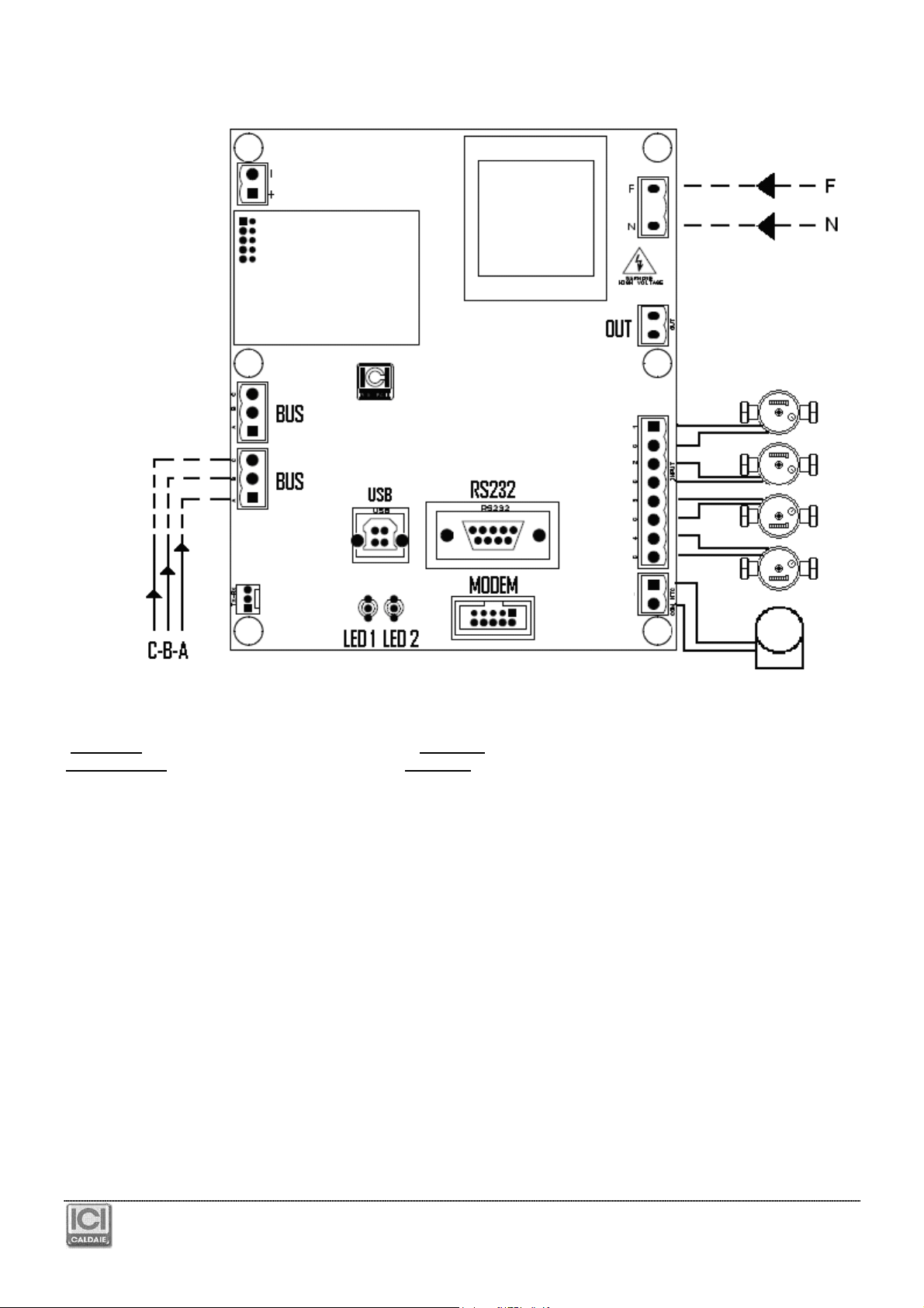
USB and RS232 CONNECTORS
allows board interfacing to a PC
MODEM CONNECTOR
allows the connection of the Master board to a specific optional GSM - GPRS modem (code CB 926)
LED DESCRIPTION
Every 10 seconds, the Master board interrogates all the boards to which it is connected.
Meaning of LED 1:
Green on flashing every 10”: The Master communicates with the slaves correctly.
Green on fixed: The Master is sending a configuration or a firmware.
Red on flashing: The Master does not find a board whose address it knows.
Meaning of LED 2:
Not used
3
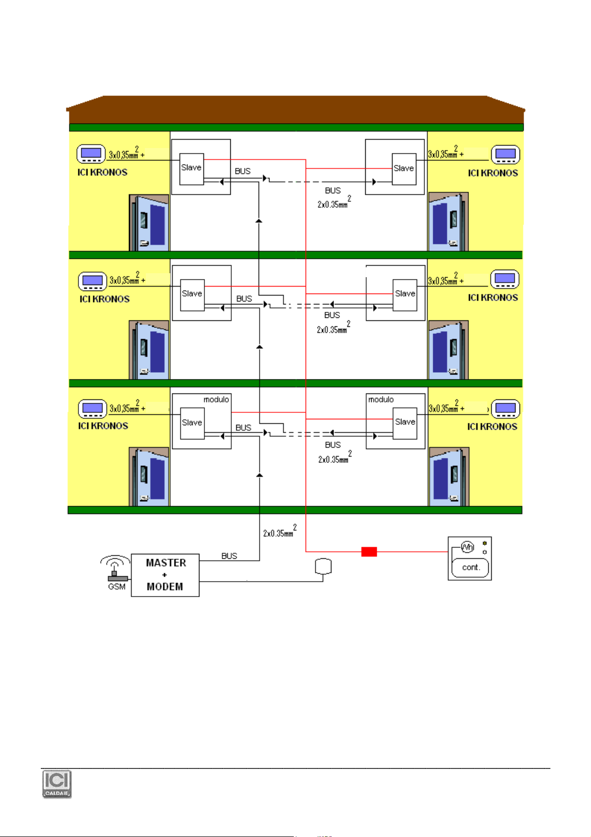
MODEM
The module is connected (or must be connected) to the Master with the appropriate flat.
The modem is power supplied directly by the board, through the flat.
Cut power from the Master when connecting the modem and when inserting the SIM card.
The SIM card must be enabled to the data traffic (not the voice!!).
The SIM must be pushed to the end run: a “click” means it is inserted.
Before inserting the SIM, deactivate the PIN using a cellular phone.
Main features:
●
GSM - GPRS Quad-Band MODEM
●
LED for logging status to GSM network
●
Buzzer for acoustic signalling
●
TTL interface
●
Compatible with NEREIX Master board
RADIO FEATURES
●
Quad-band EGSM 850/900/1800/1900 MHz
●
Emission output:
○
class 4 (2W) @ 850/900 MHz
○
class 1 (1W) @ 1800/1900 MHz
●
Sensitivity:
○
107 dBm (typ.) @ 850/900 MHz
○
106 dBm (typ.) @ 1800/1900 MHz
GPRS FEATURES
●
GPRS class 10
●
Class B mobile station
●
Coding layouts: from 1 to 4
●
PBCCH support
The green status LED means:
●
FAST FLASHING = Searching for the network
●
SLOW FLASHING = Logged onto the network
●
ON FIXED = Data connection in progress
In order to apply the optional antenna with the extension, remove the one as standard pulling the connector directly
from the module connector and insert the new one.