General information8
TECHNICAL DATA
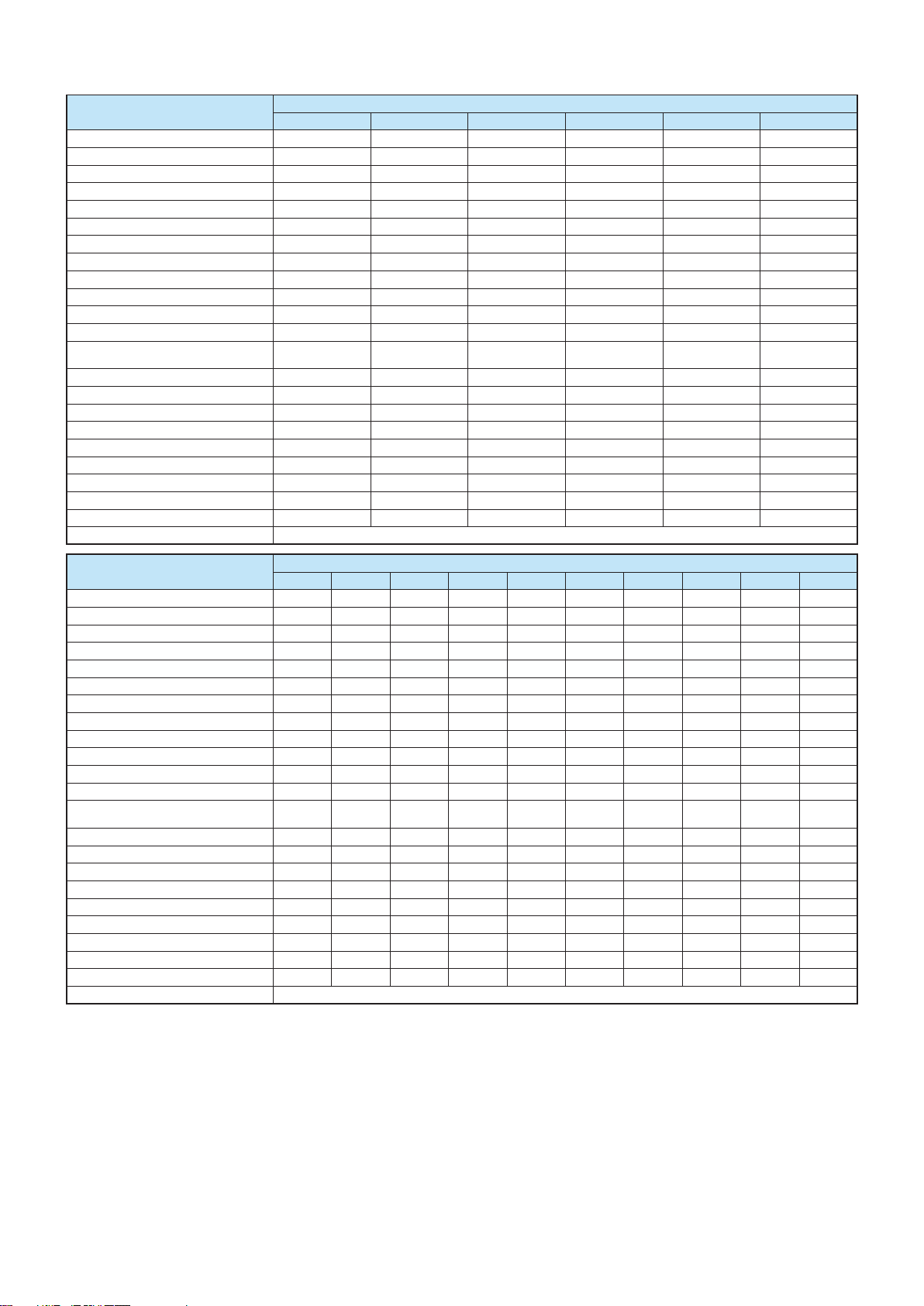
DESCRIPTION u.m. ASGX EN
3000 3500 4000 5000 6000 7000
Nominal power
kW 3000 3500 4000 5000 6000 7000
Thermal capacity
kW 3333 3888 4444 5555 6666 7777
100% efficiency (ref. NCV)
% 90 90 90 90 90 90
NG max flow rate G20
Stm3/h 352,65 411,47 470,28 587,92 705,43 822,94
NG max flow rate G30
kg/h 261,74 305,39 349,04 436,35 523,56 610,78
NG max flow rate G31
kg/h 258,9 302,08 345,26 431,62 517,89 604,16
Max flue gas flow rate
kg/h 5254,49 6130,9 7007,17 8760,01 10510,91 12261,81
100% efficiency (ref. NCV)
% 92 92 92 92 92 92
Pressure drop
mbar 15 18 15 20 13 15
Heat losses through the chimney
% 9,7 9,7 9,7 9,7 9,7 9,7
Heat losses through the casing
% 0,3 0,3 0,3 0,3 0,3 0,3
Heat losses with burner off
% 0,1 0,1 0,1 0,1 0,1 0,1
Flue gas temp. at boiler output and air
at 20 deg. C
°C 240 240 240 240 240 240
CO
2% 10 10 10 10 10 10
Hydraulic pressure drop
mbar 55 75 98 154 91 123
Rated pressure
bar 12 12 12 12 12 12
Total capacity
l 4520 5300 6650 8600 9150 10200
Total weight
kg 7000 7800 9000 11000 13000 14500
Electric supply
Volt ~ 230 230 230 230 230 230
Frequency
Hz 50 50 50 50 50 50
Insulation class
IP IP55 IP55 IP55 IP55 IP55 IP55
Electric power
W 1000 1000 1000 1000 1000 1000
Allowed fuels
Methane - LPG - Diesel - Naphtha
DESCRIPTION u.m. ASGX EN
8000 9000 10000 11000 12000 13000 14000 15000 16000 17000
Nominal power
kW 8000 9000 10000 11000 12000 13000 14000 15000 16000 17000
Thermal capacity
kW 8791 9890 10989 12087 13157 14285 15384 16339 17486 18681
100% efficiency (ref. NCV)
% 91 91 91 91 91,2 91 91 91,8 91,5 91
NG max flow rate G20
Stm3/h 930,23 1046,51 1162,91 1279,19 1392,4 1511,75 1628,03 1729,05 1850,38 1976,87
NG max flow rate G30
kg/h 690,41 776,71 863,11 949,41 1033,42 1122,01 1208,31 1283,29 1373,33 1467,21
NG max flow rate G31
kg/h 682,93 768,29 853,75 939,11 1022,22 1109,85 1195,21 1269,38 1358,45 1451,31
Max flue gas flow rate
kg/h 13860,43 15593 17327,36 19059,93 20746,76 22525,08 24257,65 25762,85 27570,66 29455,36
100% efficiency (ref. NCV)
% 93 93 93 93 93,2 93 93 93,8 93,5 93
Pressure drop
mbar 17,5 22,5 15 19 22 26 23,5 19,5 22 23
Heat losses through the chimney
% 8,7 8,7 8,7 8,7 8,5 8,7 8,7 7,9 8,2 8,7
Heat losses through the casing
% 0,3 0,3 0,3 0,3 0,3 0,3 0,3 0,3 0,3 0,3
Heat losses with burner off
% 0,1 0,1 0,1 0,1 0,1 0,1 0,1 0,1 0,1 0,1
Flue gas temp. at boiler output and air
at 20 deg. C
°C 212 212 212 212 208 212 212 195 201 212
CO
2% 10 10 10 10 10 10 10 10 10 10
Hydraulic pressure drop
mbar 161 98 66 79 94 111 128 86 98 111
Rated pressure
bar 12 12 12 12 12 12 12 12 12 12
Total capacity
l 14950 16200 20200 20200 21800 21800 23800 33000 33000 35100
Total weight
kg 15400 16300 24940 24940 25400 25400 28050 37500 37500 45000
Electric supply
Volt ~ 230 230 230 230 230 230 230 230 230 230
Frequency
Hz 50 50 50 50 50 50 50 50 50 50
Insulation class
IP IP55 IP55 IP55 IP55 IP55 IP55 IP55 IP55 IP55 IP55
Electric power
W 1000 1000 1000 1000 1000 1000 1000 1000 1000 1000
Allowed fuels
Methane - LPG - Diesel - Naphtha
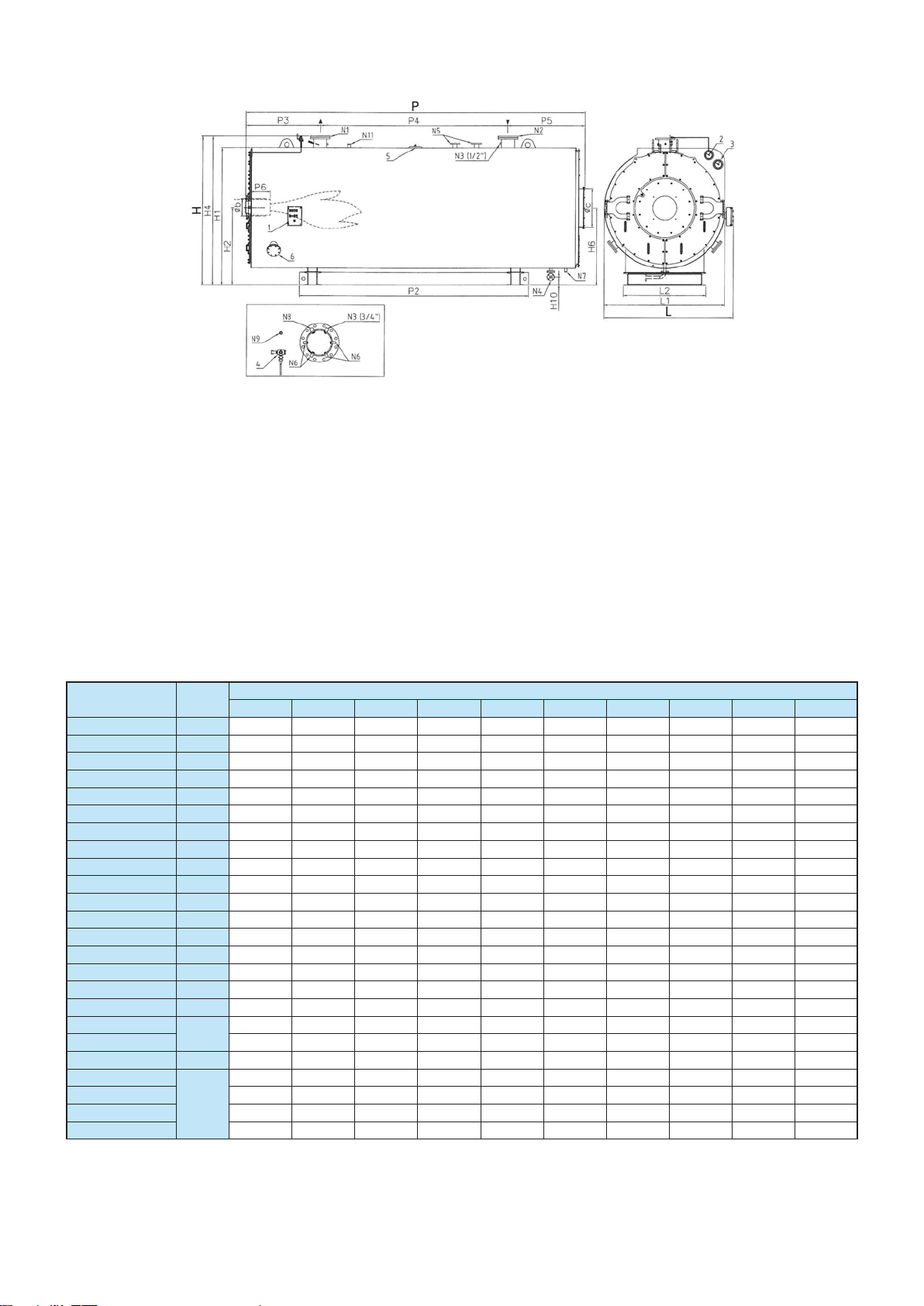
Water delivery ΔT max 30°C
Design data
Minimum/maximum temperature
-10°C / 191,7 °C
Cooke
Industries
-
Phone:
+64
9
579
2185
Email:
[email protected] Web:
www.cookeindustries.co.nz