Icom IC-M91D User manual

INSTRUCTION MANUAL
iM91D
VHF MARINE TRANSCEIVER

i
FOREWORD
Thank you for purchasing this Icom product. The IC-M91D
v h f m a r i n e t r a n s c e i v e r are designed and built with Icom’s
state of the art technology and craftsmanship. With proper
care this radio should provide you with years of trouble-free
operation.
IMPORTANT
READ ALL INSTRUCTIONS carefully and com-
pletely before using the transceiver.
SAVE THIS INSTRUCTION MANUAL—This
instruction manual contains important operating instructions
for the IC-M91D.
This instruction manual includes some functions which are
usable only when they are pre-programmed by your dealer.
Ask your dealer for details.
EXPLICIT DEFINITIONS
WORD DEFINITION
RDANGER! Personal death, serious injury or an ex-
plosion may occur.
RWARNING! Personal injury, fire hazard or electric
shock may occur.
CAUTION Equipment damage may occur.
NOTE
If disregarded, inconvenience only. No risk
of personal injury, fire or electric shock.
FEATURES
☞Floats on water
The transceiver floats in fresh or salt
water even when the supplied accesso-
ries are attached.
•Whenathird-partybatterypack,strap,an-
tenna, and so on is used, it may sink.
☞Floats and flashes
When the transceiver detects that it has
come in contact with water, the LCD
backlight, keys and trim start to blink,
making it easy to find the transceiver
even at night or in a dark environment.

ii
IN CASE OF EMERGENCY
If your vessel requires assistance, contact other vessels and
the Coast Guard by sending a distress call on Channel 16.
Or, transmit your Distress call using digital selective calling
on Channel 70.
USING CHANNEL 16
DISTRESS CALL PROCEDURE
1.“MAYDAY MAYDAY MAYDAY.”
2.“THIS IS ...............” (name of vessel).
3.Say your call sign or other indication of the vessel (AND
your 9-digit DSC ID, if you have one).
4.“LOCATED AT ...............” (your position).
5.State the nature of the distress and assistance re-
quired.
6.Give any other information which might facilitate the
rescue.
USING DIGITAL SELECTIVE CALLING (Ch 70)
DISTRESS CALL PROCEDURE
1.While lifting up the key cover, hold down [DISTRESS] for
3 seconds until you hear 3 short beeps and then one long
beep.
2.Wait for an acknowledgment on Channel 70 from a coast
station.
•Aftertheacknowledgementis received,Channel16 is
automatically selected.
3.Push and hold [PTT], then transmit the appropriate infor-
mation as listed to the left.

iii
RECOMMENDATION
CLEAN THE TRANSCEIVER THOROUGHLY WITH FRESH
WATER after exposure to saltwater. Otherwise, the trans-
ceiver's keys, switches and controllers may become inoper-
able due to salt crystallization.
NOTE: DO NOT wash the transceiver in water if there is any
reason to suspect the waterproofing may not be effective. For
example, in cases where the battery pack rubber seal is dam-
aged, the transceiver/battery pack is cracked or broken, or
has been dropped, or when the battery pack is detached from
the transceiver.
RWARNING! NEVER connect the transceiver to an
AC outlet. This may pose a fire hazard or result in an electric
shock.
RWARNING! NEVER hold the transceiver so that
the antenna is very close to, or touching exposed parts of
the body, especially the face or eyes, while transmitting. The
transceiver will perform best if the microphone is 5 to 10 cm
away from the lips and the transceiver is vertical.
RWARNING! NEVER operate the transceiver with
other audio accessories at high volume levels. Hearing ex-
perts advise against continuous high volume operation. If you
experience a ringing in your ears, reduce the volume level or
discontinue use.
DO NOT modify the transceiver. The transceiver warranty does
not cover any problems caused by unauthorized modification.
BE CAREFUL! The transceiver will become hot when
operating it continuously for long periods of time.
KEEP the transceiver and microphone at least 1 m away
from the vessel’s magnetic navigation compass.
KEEP the transceiver out of the reach of children.
PRECAUTIONS

iv
PRECAUTIONS
CAUTION: MAKE SURE the flexible antenna, bat-
tery pack and jack cover are securely attached to the trans-
ceiver, and that the antenna and battery pack are dry before
attachment. Exposing the inside of the transceiver to dust or
water will result in serious damage to the transceiver.
DO NOT operate the transceiver near unshielded electri-
cal blasting caps or in an explosive atmosphere.
DO NOT
push [PTT] when not actually intending to transmit.
DO NOT use or place the transceiver in direct sunlight or
in areas with temperatures below –15°C or above +55°C.
The basic operations, transmission and reception of the
transceiver are guaranteed within the specified operating
temperature range. However, the LCD display may not be
operate correctly, or show an indication in the case of long
hours of operation, or after being placed in extremely cold
areas.
DO NOT use harsh solvents such as benzine or alcohol
when cleaning, as they will damage the transceiver surfaces.
BE CAREFUL! The IC-M91D meets IPX7* requirements
for dust-tight and waterproof protection. However, once the
transceiver has been dropped, dust-tight and waterproof pro-
tection cannot be guaranteed because of possible damage to
the transceiver’s case or the waterproof seal.
* Only when the jack cover or the optional HM-167 is at-
tached.
Even when the transceiver power is OFF, a slight current still
flows in the circuits. Remove the battery pack or batteries
from the transceiver when not using it for a long time. Other-
wise, the installed battery pack or batteries will become ex-
hausted, and will need to be recharged or replaced.
BE CAREFUL! Even if the volume level is set low, the
beeps of the Float ’n Flash, DSC alarm and AquaQuake func-
tions are very loud.
MAKE SURE to turn the transceiver power OFF before
connecting the supplied/optional equipment.

v
FOREWORD ......................................................................... i
IMPORTANT.......................................................................... i
EXPLICIT DEFINITIONS....................................................... i
FEATURES............................................................................ i
IN CASE OF EMERGENCY................................................. ii
RECOMMENDATION .......................................................... iii
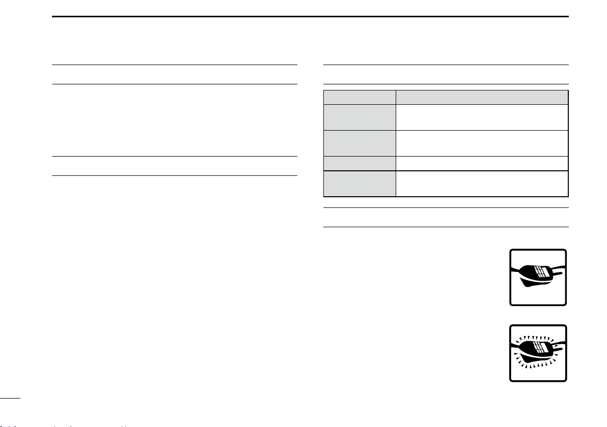
PRECAUTIONS...............................................................iii–iv
TABLE OF CONTENTS................................................... v–vi
COUNTRY CODE LIST ....................................................... vi
1 OPERATING RULES ........................................................1
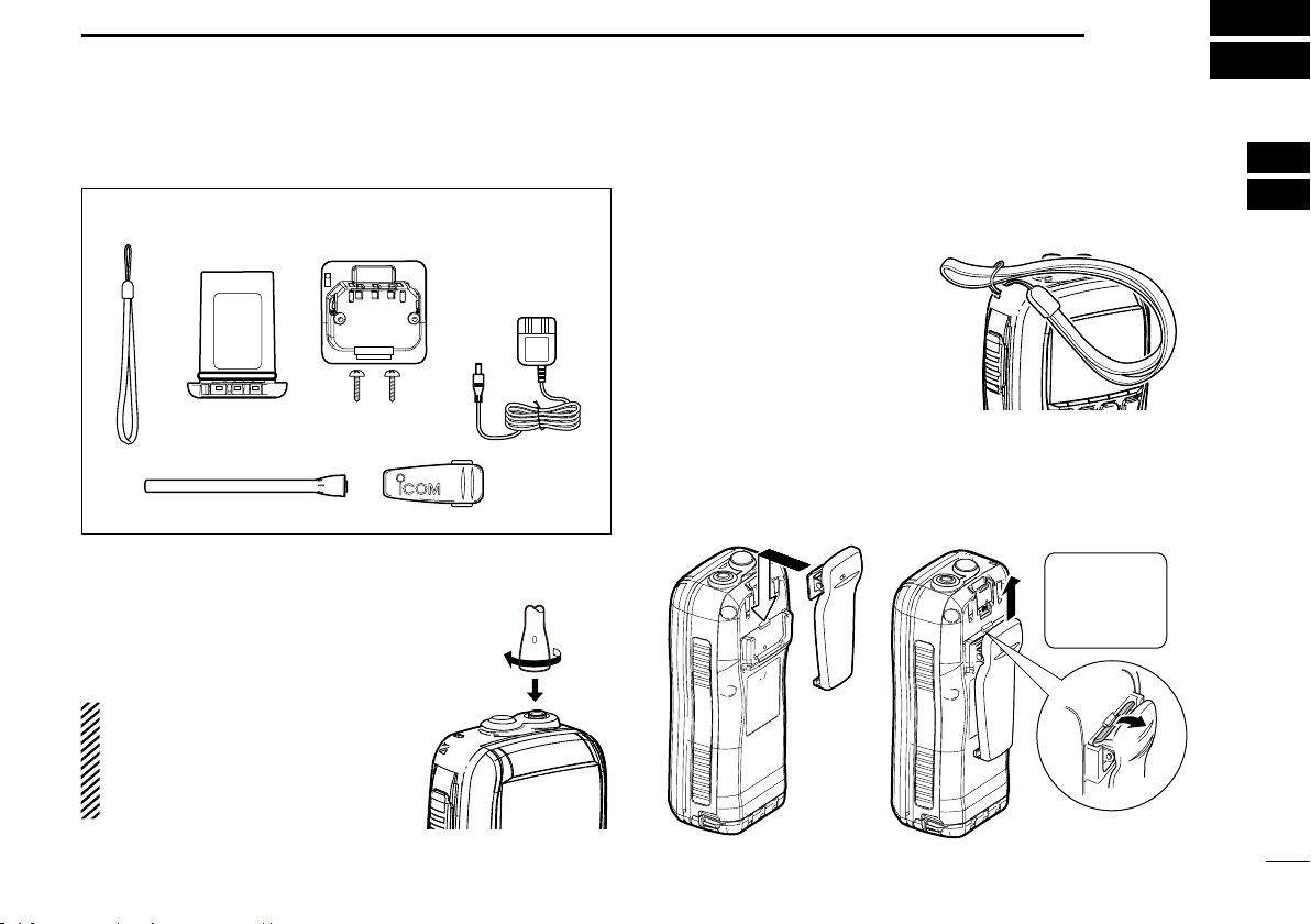
2 SUPPLIED ACCESSORIES AND ATTACHMENTS .....2–3
Supplied accessories■...................................................2
Attachments■.................................................................2
3 PANEL DESCRIPTION .................................................4–9
Front, top, side and rear panels■...................................4
Softkeys■.......................................................................6
Function display■..........................................................7
Softkey function■............................................................9
4 PREPARATION .........................................................10–11
MMSI code programming■...........................................10
ATIS code programmin■g.............................................11
5 BASIC OPERATION .................................................12–17
Channel selection■......................................................12
Call channel programming■.........................................13
Adjusting the volume level■..........................................14
Adjusting the squelch level■.........................................14
Receiving and transmitting■.........................................14
Lock function■..............................................................15
Monitor function■.........................................................15
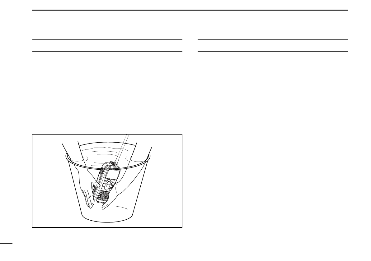
AquaQuake water draining function■...........................16
Backlight setting■.........................................................16
Channel name programming■......................................16
6 SCAN OPERATION (Except for the Dutch version)..18–19
Scan types■.................................................................18
Setting Favorite channels■...........................................19
Starting a scan■...........................................................19
7 DUALWATCH/TRIWATCH...............................................20
Description■.................................................................20
Operation■...................................................................20
8 DSC OPERATION.....................................................21–64
DSC address ID■........................................................21
Position and time programming■..................................24
Distress call■................................................................25
Transmitting DSC calls■...............................................29
Receiving DSC calls■..................................................46
Received Call log■.......................................................58
TABLE OF CONTENTS

vi
Icom, Icom Inc. and the Icom logo are registered trademarks of Icom Incor-
porated (Japan) in Japan, the United States, the United Kingdom, Germany,
France, Spain, Russia and/or other countries.
TABLE OF CONTENTS
• ISO 3166-1
Country Codes Country Codes
1
2
3
4
5
6
7
8
9
10
11
12
13
14
15
16
17
Austria
Belgium
Bulgaria
Croatia
Czech Republic
Cyprus
Denmark
Estonia
Finland
France
Germany
Greece
Hungary
Iceland
Ireland
Italy
Latvia
AT
BE
BG
HR
CZ
CY
DK
EE
FI
FR
DE
GR
HU
IS
IE
IT
LV
18
19
20
21
22
23
24
25
26
27
28
29
30
31
32
33
Liechtenstein
Lithuania
Luxembourg
Malta
Netherlands
Norway
Poland
Portugal
Romania
Slovakia
Slovenia
Spain
Sweden
Switzerland
Turkey
United Kingdom
LI
LT
LU
MT
NL
NO
PL
PT
RO
SK
SI
ES
SE
CH
TR
GB
COUNTRY CODE LIST
Transmitted Call log■....................................................60
DSC Settings■.............................................................61
9 OTHER FUNCTIONS ................................................65–75
MOB (Man OverBoard)■..............................................65
Waypoint■....................................................................68
Navigation■..................................................................72
Compass screen■........................................................74
GPS status screen■.....................................................74
10 MENU SCREEN OPERATION................................76–82
Menu screen operation■..............................................76
Menu screen items■.....................................................77
Radio Settings items■..................................................78
Configuration items■....................................................79
11 BATTERY CHARGING............................................83–87
Battery caution■...........................................................83
Regular battery charger■.............................................85
Optional battery chargers■...........................................86
12 OPTIONAL SPEAKER-MICROPHONE........................88
HM-167 descriptions■..................................................88
Attachment■.................................................................88
13 TROUBLESHOOTING...................................................89
14 SPECIFICATIONS AND OPTIONS.........................90–91
Specifications■.............................................................90
Options■.......................................................................91
15 CHANNEL LIST ............................................................92

1
1OPERATING RULES
PrioritiesD
•Read all rules and regulations pertaining to priorities and
keep an up-to-date copy handy. Safety and distress calls
take priority over all others.
•YoumustmonitorChannel16whenyouarenotoperating
on another channel.
•Falseorfraudulentdistresscallsareprohibitedunderlaw.
PrivacyD
•Informationoverheardbutnotintendedforyoucannotlaw-
fully be used in any way.
•Indecentorprofanelanguageisprohibited.
Radio licensesD
(1) SHIP STATION LICENSE
You must have a current radio station license before using
the transceiver. It is unlawful to operate a ship station which
is not licensed.
Inquire through your dealer or the appropriate government
agency for a Ship-Radiotelephone license application. This
government-issued license states the call sign which is your
craft’s identification for radio purposes.
(2) OPERATOR’S LICENSE
A Restricted Radiotelephone Operator Permit is the license
most often held by small vessel radio operators when a radio
is not required for safety purposes.
The Restricted Radiotelephone Operator Permit must be
posted or kept with the operator. Only a licensed radio opera-
tor may operate a transceiver.
However, non-licensed individuals may talk over a transceiv-
er if a licensed operator starts, supervises, ends the call and
makes the necessary log entries.
A current copy of the applicable government rules and regu-
lations is only required to be on hand for vessels in which
a radio telephone is compulsory. However, even if you are
not required to have these on hand it is your responsibility to
be thoroughly acquainted with all pertinent rules and regula-
tions.

2
2
SUPPLIED ACCESSORIES AND ATTACHMENTS
1
2
3
4
5
6
7
8
9
10
11
12
13
14
15
16
Supplied accessories■
Battery packHandstrap
Belt clip
Battery charger
(with 2 screws)
Antenna
AC adapter
(Not supplied or
different type may be
supplied, depending
on the version)
Attachments■
Flexible antennaD
Connect the supplied flexible antenna
to the antenna connector.
CAUTION:
•NEVER carry the transceiver by hold-
ing the antenna.
•Transmittingwithoutanantennamay
damage the transceiver.
HandstrapD
Pass the handstrap through
the loop on the back side of
the transceiver as illustrated
at right. This facilitates carry-
ing.
Belt clipD
Attach/detach the belt clip to
the transceiver as illustrated below.
To attach the belt clip To detach the belt clip
Be careful!
Do not break
your finger
nails.
w
q

3
2SUPPLIED ACCESSORIES AND ATTACHMENTS
Battery packD
To remove the battery pack:
Turn the screw counter clockwise one quarter turn, then pull
the battery pack in the direction of the arrow, as shown below.
To attach the battery pack:
Insert the battery pack completely into the transceiver, then
turn the screw clockwise one quarter turn.
NEVER remove or insert the battery pack when the trans-
ceiver is wet or soiled. This may result water or dust get-
ting into the transceiver or battery pack and may result in
the transceiver being damaged.
NOTE: When removing or attaching the battery pack, use
a coin or standard screwdriver to loosen or tighten the bot-
tom screw.
CAUTION:
When attaching or removing a battery pack, make sure
the rubber seal is set in the groove of the battery pack
correctly. If the seal is not correctly in the groove, it may
be damaged when attaching the battery pack. If the seal is
damaged, waterproof protection is not guaranteed.
Make sure the rubber seal is properly seated in the
groove and dust or other material does not adhere to it.
Battery pack Battery pack
Rubber seal
Groove
Correct position Incorrect position
NOTE:
When attaching a battery pack, make sure dust or other
material does not adhere to the rubber seal. If dust or other
material is on the seal when attaching a battery pack,
waterproof protection may not be guaranteed.
Screw position
when removing battery
Screw position
when attaching battery

4
3
PANEL DESCRIPTION
1
2
3
4
5
6
7
8
9
10
11
12
13
14
15
16
Front, top, side and rear panels■
Function
display
(pp. 7, 8, 9)
Microphone
r
e
y
w
q
!0
i
u
o
Speaker
!1
/+%
t
!2
Distress key
(p. 25)
q ANTENNA CONNECTOR (p. 2)
Connects to the supplied antenna.
w
SPEAKER-MICROPHONE CONNECTOR [SP MIC]
(p. 88)
Connects to the optional external speaker-microphone.
NOTE: Attach the [SP MIC] cap when the optional
speaker-microphone is not used. Otherwise, water will
get into the transceiver.
e PTT SWITCH [PTT]
Hold down to transmit; release to receive. (p. 14)
rMENU KEY
Push to enter or exit the Menu screen.
t LEFT AND RIGHT KEYS [Ω]/[≈]
Push to switch to the previous or next key function that➥
is assigned to the softkeys. (p. 9)
Push to select the desired character or number in the➥
table while in the channel name, position, MMSI code
programming mode, and so on. (pp. 10, 16, 24)
y VOLUME/SQUELCH KEY [VOL/SQL]
Push to enter the volume level adjustment mode.➥
(p. 14)
Push again while in the volume level adjustment mode➥
to enter the squelch level adjustment mode.
Hold down for 1 second to activate the monitor function.➥
(p. 15)
u POWER KEY [ ]
Hold down for 1 second to turn the power ON or OFF.

5
3PANEL DESCRIPTION
Front, top and rear panels (Continued)■
iCHANNEL 16 KEY [16/C]
Push to select Channel 16. (➥p. 12)
Hold down for 1 second to select the Call channel.➥
(p. 12)
Hold down for 3 seconds to enter the Call channel➥
programming mode when the Call channel is selected.
(p. 13)
oENTER KEY
Push to set the input data, selected item, and so on.
!0 CLEAR/LOCK KEY [ ]
Push to cancel the entered data, or to return to the pre-➥
vious screen.
Hold down for 1 second to turn the key lock function ON➥
or OFF. (p. 15)
!1
UP AND DOWN/CHANNEL SELECT KEYS [∫•CH]/[√•CH]
Push to select the operating channels, Menu items,➥
Menu settings, and so on. (p. 77)
➥
Push to check Favorite (TAG) channels, change the
scanning direction or manually resume a scan. (p. 19)
!2 SOFTKEYS
Slide the menu by pushing the [Ω]/[≈]keys, then push ei-
ther of the 4 softkeys to select a menu displayed at the
bottom of the LCD display.
See Softkeys on the next page for more details. (p. 6)
Function
display
(pp. 7, 8, 9)
Microphone
r
e
y
w
q
!0
i
u
o
Speaker
!1
/+%
t
!2
Distress key
(p. 25)

6
3
PANEL DESCRIPTION
1
2
3
4
5
6
7
8
9
10
11
12
13
14
15
16
Softkeys■
The desired functions as described below can be assigned
in the Menu screen.
Scan [ ]* (p. 18)
Push to start or stop a Normal or Priority scan.
* Except for the Dutch version.
Dualwatch/Tri-watch [ ](p. 20)
Push to start a Dualwatch or Tri-watch*.➥
Push to stop a Dualwatch or Tri-watch when either is➥
activated.
* Except for the Dutch version.
High/Low [ ](p. 14)
Push to set the power to high or low.
•Somechannelsaresettoonlylowpower.
Channel [ ] (p. 12)
Push to select either the regular channels.
AquaQuake [ ](p. 16)
While holding down, the AquaQuake function is activated
to clear water away from the speaker grill.
Favorite channel [ ] (p. 19)
Push to set or clear the displayed channel as a Favorite➥
(Tag) channel.
Hold down for 3 seconds to clear or set all Favorite➥
channels in the selected channel group.
Name [ ](p. 16)
Push to enter the channel name programming mode.
Backlight [ ](p. 16)
Push to enter the LCD and key backlight brightness ad-
justment mode.
•Whileintheadjustmentmode,push[∫]/[√][Ω]/[≈] to adjust the
brightness of the LCD and key backlight.
MOB [ ] (p. 65)
Push to enter “MOB” in the menu screen.➥
Hold down for 1 second to memorize the current position➥
as the MOB (Man OverBoard) point.
Waypoint [ ] (p. 68)
Push to enter “WAYPOINT” in the menu screen.➥
➥
Hold down for 1 second to memorize the current position
as a Waypoint.

7
3PANEL DESCRIPTION
Function display■
q
!4
wrtyui
!3
o
!0
!7
!6
!5
e
!2
!1
q BUSY/TRANSMIT INDICATOR (p. 14)
“BUSY” appears when receiving a signal or when the➥
squelch opens.
“TX” appears while transmitting.➥
“MONI” appears while the monitor function is activated.➥
w POWER ICON (p. 14)
“HI” appears when high power is selected.➥
“LOW” appears when low power is selected.➥
e
CHANNEL GROUP ICON (p. 13)
Shows which channel group is selected, a U.S.A. “USA,”
International “INT,” ATIS “ATIS” or DSC “DSC”, depending
on the transceiver version.
r CALL CHANNEL ICON (p. 12)
Appears when Call channel is selected.
Navigation [ ] (p. 72)
After holding down [MOB], or in the MOB or Waypoint list
screen, push this key to start navigating to the selected
position.
Compass [ ](p. 74)
Push to display the compass screen to show the vessel’s
course heading, SOG (Speed Over Ground) and COG
(Course Over Ground).
Log [ ] (p. 58)
Push to enter “RCVD CALL LOG” in the DSC CALLS menu.
Softkeys (Continued)■

8
3
PANEL DESCRIPTION
1
2
3
4
5
6
7
8
9
10
11
12
13
14
15
16
!3 KEY ICONS (p. 9)
Shows the programmed function of the softkeys on the
front panel.
!4 TIME ZONE INDICATOR
Shows the current time when GPS data is received, or➥
the time is manually programmed.
•“??” will blink when invalid GPS data is received for 30
seconds.
•“??” will blink when manually input GPS data is no longer
valid after 4 hours, and then “NO TIME” will appear after
23.5 hours.
“LOCAL” appears when the offset time is set.➥
➥“NO TIME” appears when no GPS data is received and
no time data is manually input.
➥
“MNL” appears when the time is manually programmed.
t DUPLEX ICON (p. 13)
Appears when a duplex channel is selected.
y FAVORITE CHANNEL ICON (p. 19)
Appears while a Favorite (TAG) channel is selected.
u MESSAGE ICON (p. 46)
Blinks when there is an unread message.
i GPS ICON
Stays ON while the GPS data is received, and a valid➥
position is received.
Blinks when an invalid position is being received.➥
o SWITCH ICON (p. 62)
Appears when the “CH 16 SWITCH” in DSC Settings is set
to ‘OFF.’
!0 LOCK ICON (p. 15)
Appears while the lock function is activated.
!1 CHANNEL NUMBER READOUT
Shows the selected operating channel number.
•Whenasimplexchannelisselected,“A”appears.
!2 CHANNEL NAME FIELD (p. 16)
The channel name appears, if programmed.➥
“DSC CHECK” blinks while receiving on channel 70.➥

9
3PANEL DESCRIPTION
Softkey function■
Various functions can be assigned to the softkeys.
When the key function is assigned, the key icon is displayed
above the softkeys, as shown below.
Softkey function selectionD
When “Ω” or “≈” is displayed beside the key icon, pushing [Ω]
or [≈] sequentially displays the previous or next key function
that is assigned to the softkey.
Push Push
*Push this key to start or stop a scan.
*
The order of the key icons may differ, depending on the
preprogramming.
Function Display (Continued)■
!5 POSITION INDICATOR
Shows the current position when valid GPS data is re-➥
ceived or the position is manually programmed.
•“??” will blink when invalid GPS data is received for 30
seconds.
•“??” will blink when manually input GPS data is no longer
valid after 4 hours, and then “NO POSITION” will appear
after 23.5 hours.
•“NOPOSITION” appearswhen noGPS data is received,
and no position is manually input.
!6 SCAN INDICATOR*
“SCAN 16” is displayed during a Priority scan; “SCAN”➥
appears during a Normal scan. (p. 18)
“DUAL 16” appears during Dualwatch;“TRI 16” appears➥
during Tri-watch. (p. 20)
* Except for the Dutch version.
!7 BATTERY INDICATOR
Shows the battery’s remaining power.
Indication
Full Middle Charging
required No battery
Battery level
blinks when the battery is over charged.

10
4
PREPARATION
1
2
3
4
5
6
7
8
9
10
11
12
13
14
15
16
MMSI code programming■
The 9 digit MMSI (Maritime Mobile Service Identity: DSC self
ID) code can be programmed at power ON.
This initial code setting can be performed only once.
After being set, it can be changed by only your dealer
or distributor. If your MMSI code has already been pro-
grammed, this programming is not necessary.
Hold down [q] to turn ON the power.
•Threeshortbeepssound,and“NODSCMMSI”isdisplayed.
Push [ENTER] to start the MMSI code programming.w
•Push[CLEAR]twicetocanceltheprogramming,andgotothe
normal operating screen. In this case, the transceiver cannot
make a DSC call. To program the MMSI code, turn OFF the
power, then turn it ON again.
Enter your MMSI code in the following manner:e
•Selectadesirednumberusing[∫]/[√]/[Ω]/[≈].
•Push[ENTER]tosetit.
•Tomovethecursor,selecteitherarrow,“←” or “→,” then push
[ENTER].
Repeat stepr e to enter all 9 digits.
After entering the 9 digit code, “FINISH” is automaticallyt
selected, and then push [ENTER] to set it.
The “MMSI CONFIRMATION” screen is displayed.y
Enter your MMSI code again for confirmation.u
•Enterinthesamemannerasstepsethrough t.
When your MMSI code programming is successfully com-i
pleted, the screen as shown below is briefly displayed.
•Afterthat,thenormaloperatingscreenisdisplayed.
The programmed MMSI code can be checked in the MENU
screen. (p. 77)
NOTE: Depending on the transceiver version, the ATIS
code programming is required after programming the
MMSI code. See the next page for details.

11
4PREPARATION
The 10 digit ATIS (Automatic Transmitter Identification Sys-
tem) code can be programmed at power ON.
This initial code setting can be performed only once.
After being set, it can be changed by only your dealer
or distributor. If your ATIS code has already been pro-
grammed, this programming is not necessary.
After programming the MMSI code, “Push [ENTER] toq
Register Your ATIS” is displayed.
Push [ENTER] to start the ATIS code programming.w
•Push[CLEAR]twicetocanceltheprogramming,andgotothe
normal operating mode. In this case, the ATIS function is dis-
abled. To program the ATIS code, turn OFF the power, then
turn it ON again.
Enter your ATIS code in the following manner:e
•Selectadesirednumberusing[∫]/[√]/[Ω]/[≈].
•Push[ENTER]tosetit.
•Tomovethecursor,selecteitherarrow,“←” or “→,” then push
[ENTER].
Repeat stepr e to enter all 10 digits.
After entering the 10 digit code, “FINISH” is automaticallyt
selected, and then push [ENTER] to set it.
The “ATIS CONFIRMATION” screen is displayed.y
Enter your ATIS code again for confirmation.u
•Enterinthesamemannerasstepsethrough t.
When your ATIS code programming is successfully com-i
pleted, the screen as shown below is briefly displayed.
•Afterthat,thenormaloperatingscreenisdisplayed.
The programmed ATIS code can be checked in the MENU
screen. (p. 77)
ATIS code programming■(For Dutch and German versions)

12
5
BASIC OPERATION
1
2
3
4
5
6
7
8
9
10
11
12
13
14
15
16
Channel selection■
IMPORTANT: Prior to using the transceiver for the first
time, the battery pack must be fully charged for optimum
life and operation. To avoid damage to the transceiver,
turn the power OFF while charging.
Channel 16D
Channel 16 is the distress and safety channel. It is used for
establishing initial contact with a station and for emergency
communications. Channel 16 is monitored during both Dual-
watch and Tri-watch*. While in the standby condition, you
must monitor Channel 16.
* Except for the Dutch version.
Push [16/C] to select Channel 16.q
Push [wCHAN] to return to the selected channel before
Channel 16, or push [∫](CH) or [√](CH) to select an op-
erating channel.
Call channelD
Each regular channel group has separate leisure-use call
channels. The call channel is monitored during Tri-watch*.
The call channels can be programmed and are used to store
your most often used channel in each channel group for quick
recall. (p. 13)
* Except for the Dutch version.
Hold down [16/C]qfor 1 second to select Call channel.
•“CALL”andthecallchannelnumberaredisplayed.
•Callchannelcanbere-programmed.Seethe“Callchannelpro-
gramming” on page 13 for details.
Pushw[CHAN]to return to the selected channel before the
call channel, or push [∫](CH) or [√](CH) to select the op-
erating channel.
Hold down [16/C] key
for 1 second
Push [16/C] key

13
5BASIC OPERATION
Channel group selectionD
There are preprogrammed international channels for the IC-
M91D. For U.K. transceiver version, there are preprogrammed
U.S.A. channels in addition to International channels. For
Dutch and German versions, there are preprogrammed ATIS
and DSC* channels in addition to International channels.
Except for the Europe version, a channel group suitable for
your operating area is selectable, as described below.
Push [MENU].q
Push [wY]/[Z] to select “Radio Settings”.
Push [eY]/[Z] to select “CHAN Group”, and then push [EN-
TER].
r Push [Y]/[Z] to select the desired channel group, and then
push [ENTER].
t Push [EXIT] to exit the Menu screen.
Pushy[Y](CH)/[Z](CH) to select a channel.
•“DUP”appearsforduplexchannels.
•“A”appearsforsimplexchannel.
* German version only.
Call channel programming■
You can program the call channel with your most often-used
channels in each channel group for quick recall.
Select theqdesired channel group to be programmed, as
described to the left.
Hold down [16/C] for 1 second to select the call channel ofw
the selected channel group.
•“CALL”andcallchannelnumberaredisplayed.
Hold down [16/C] again for 3 seconds until long beep stopse
with two short beeps.
•Thechannelprogrammingmodescreenisdisplayed.
r Push [Y](CH)/[Z](CH) to select the desired channel.
t Push [ENTER] to program the selected channel as the call
channel.
•
The display automatically returns to the normal operating mode.
When the U.S.A. channel group is
selected.
Other manuals for IC-M91D
3
Table of contents
Other Icom Transceiver manuals