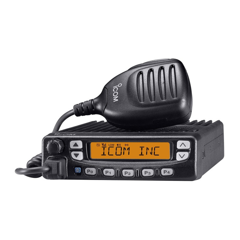
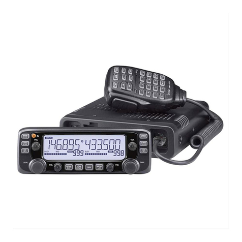
Icom ID-50A Installation guide

BASIC MANUAL
This device complies with part 15 of the FCC
Rules. Operation is subject to the condition that
this device does not cause harmful interference.
VHF/UHF TRANSCEIVER
ID-50A
ID-50E
WARNING: MODIFICATION OF THIS DEVICE
TO RECEIVE CELLULAR RADIOTELEPHONE
SERVICE SIGNALS IS PROHIBITED UNDER
FCC RULES AND FEDERAL LAW.

i
BASIC MANUAL
Thank you for choosing this Icom product. This product is designed and built with Icom’s
state of the art technology and craftsmanship. With proper care, this product should
provide you with years of trouble-free operation.
This product combines traditional analog technologies with Digital Smart Technologies for
Amateur Radio (D-STAR), for a balanced package.
■Important
READ ALL INSTRUCTIONS carefully and completely before using the transceiver.
SAVE THIS INSTRUCTION MANUAL— This instruction manual contains basic operating
instructions for the ID-50A/ID-50E. For advanced operating instructions, see the
Advanced manual for details.
The Advanced manual can be downloaded from the following internet address:
https://www.icomjapan.com/support/
■Features
zD-STAR operation: The ID-50A/ID-50E has the D-STAR Repeater (DR) function.
zThe Dualwatch function can simultaneously receive two dierent bands or modes.
zA built-in GPS receiver to check your current location.
zThe Voice recorder records your QSO conversation, voice audio for TX, and
microphone voice audio.
zA microSD card slot that can accept dierent cards to backup settings, various
memories, the GPS log, and so on.
zA USB connector for data transmission or battery charging.
zThe waterfall display of the Band Scope function to display signal strengths over time.
■Explicit denitions
WORD DEFINITION
RDANGER! Personal death, serious injury or an explosion may occur.
RWARNING! Personal injury, re hazard or electric shock may occur.
CAUTION Equipment damage may occur.
NOTE If disregarded, inconvenience only. No risk of personal injury, re or
electric shock.
Icom is not responsible for the destruction, damage to, or performance of any Icom or
non-Icom equipment, if the malfunction is because of:
• Force majeure, including, but not limited to, res, earthquakes, storms, oods,
lightning, or other natural disasters, disturbances, riots, war, or radioactive
contamination.
• The use of Icom transceivers with any equipment that is not manufactured or approved
by Icom.
About weld lines
This product’s surfaces may have streaks called “weld lines,” that occur during the
molding process, and are not cracks or aws.

ii
BASIC MANUAL
1
7
4
10
15
18
2
8
13
5
11
16
3
9
14
6
12
17
■Supplied Accessories
Antenna
Hand strap Belt clipBattery pack
NOTE: Some accessories are not supplied, or the shape is dierent, depending on the
transceiver version.
■FCC information
This equipment has been tested and found
to comply with the limits for a Class B digital
device, pursuant to part 15 of the FCC
Rules. These limits are designed to provide
reasonable protection against harmful
interference in a residential installation.
This equipment generates, uses, and can
radiate radio frequency energy and, if not
installed and used in accordance with the
instructions, may cause harmful interference
to radio communications. However, there is
no guarantee that interference will not occur
in a particular installation. If this equipment
does cause harmful interference to radio or
television reception, which can be determined
by turning the equipment o and on, the user
is encouraged to try to correct the interference
by one or more of the following measures:
• Reorient or relocate the receiving antenna.
• Increase the separation between the
equipment and receiver.
• Connect the equipment into an outlet on
a circuit dierent from that to which the
receiver is connected.
• Consult the dealer or an experienced
radio/TV technician for help.
CAUTION: Changes or modications to this
device, not expressly approved by Icom
Inc., could void your authority to operate this
device under FCC regulations.
■Disposal
The crossed-out wheeled-bin
symbol on your product, literature,
or packaging reminds you that in
the European Union, all electrical
and electronic products, batteries,
and accumulators (rechargeable batteries)
must be taken to designated collection
locations at the end of their working life. Do
not dispose of these products as unsorted
municipal waste. Dispose of them according
to the laws in your area.
■About CE and DOC
Hereby, Icom Inc. declares that
the versions of ID-50E which
have the “CE” symbol on the
product, comply with the essential
requirements of the Radio Equipment Directive,
2014/53/EU, and the restriction of the use of
certain hazardous substances in electrical and
electronic equipment Directive, 2011/65/EU.
The full text of the EU declaration of conformity
is available at the following internet address:
https://www.icomjapan.com/support/
For Canada:
This device contains licence-exempt
transmitter(s)/receiver(s) that comply
with Innovation, Science and Economic
Development Canada (ISED)’s licence-
exempt RSS(s). Operation is subject to the
following two conditions: (1) this device may
not cause interference, and (2) this device
must accept any interference, including
interference that may cause undesired
operation of the device.
USB cable

iii
BASIC MANUAL
■About the ID-50A/ID-50E manuals
You can use the following manuals to understand and operate this transceiver.
(As of December 2023)
TIP: You can download each manual and guide from the Icom website:
https://www.icomjapan.com/support/
Enter “ID-50A” or “ID-50E” into the Search box on the site.
Basic manual (This manual)
Instructions for basic operations and precautions.
Advanced manual (PDF type)
Instructions for the advanced operations, as shown below.
• Using a microSD card • Memory operation
• Battery operation • Scan operation
• FM Radio operation • Repeater and duplex operations
• D-STAR operation • Set mode
• GPS operation • Other functions
• Voice TX operation • Firmware updating
• Voice recorder operation • Options
Updating the repeater list (PDF type)
Instructions for the steps to update the repeater list.
Using the GPS Logger function (PDF type)
Instructions for operating the GPS Logger function, that saves location data from a GPS
receiver onto a microSD card as a log.
About the DV Gateway function (PDF type)
Instructions for the system requirements or operations to use the DV Gateway function.
CI-V Reference Guide (PDF type)
Describes the control commands used in remote control operation (serial communication using
CI-V).
LIf necessary, you can see a glossary of HAM radio terms that can be downloaded from the
Icom website.
LTo read the manuals or Guide, Adobe®Acrobat®Reader®is required. If you have not
installed it, please download the Adobe®Acrobat®Reader®and install it on your PC. You can
download it from Adobe Systems Incorporated’s website.
■About UKCA DOC
To obtain the UKCA Declaration of Conformity, please contact Icom UK Limited by email

iv
BASIC MANUAL
1
7
4
10
15
18
2
8
13
5
11
16
3
9
14
6
12
17
■Important Notes
DWhen using the GPS receiver
• GPS signals cannot pass through metal objects. When using the transceiver inside a
vehicle, you may not receive GPS signals. We recommend you use it near a window.
• The Global Positioning System (GPS) is built and operated by the U.S. Department of
Defense. The Department is responsible for accuracy and maintenance of the system.
Any changes by the Department may aect the accuracy and function of the GPS system.
• The GPS receiver is installed under the transceiver’s top panel. Therefore, when the
GPS receiver is activated, do not cover the top with anything that will block the satellite
signals.
• The GPS receiver may not work if used in the following locations:
- Tunnels or high-rise buildings
- Underground parking lots
- Under a bridge or viaduct
- In remote forested areas
- Under bad weather conditions (rainy or cloudy day)
• The GPS receiver may not work if the transceiver operates near 467.090 MHz on the A
band, or 468.000 MHz on the B band. This is due to signals made in the internal circuit,
and does not indicate a transceiver malfunction.
DSpurious signals
Using the Dualwatch function, or monitoring the broadcast FM radio band while using
the Dualwatch function, may generate certain spurious signals, or noise may be heard,
depending on the combination of the operating band and mode. These do not indicate a
transceiver malfunction.
DAbout charging with the power ON
When the battery pack is attached, and the optional CP-12L or OPC-254L external
DC power cable is connected to [DC IN], the battery pack can be charged even if the
transceiver is ON. This operation may generate certain spurious signals, and the S-meter
may appear, or noise may be heard.
NOTE:
• The charging time with the power ON may dier, depending on the operating condition.
• The external DC power supply voltage must be between 10 ~ 16 V, and the current capacity
must be more than 2.5 A to charge the battery pack with the power ON.
• When you operate the transceiver while charging, and if you cannot receive signals
correctly, set “Charging (Power ON)”* to “OFF.”
* [MENU] > SET > Function > Charging (Power ON) (Default: ON)
The GPS receiver
is installed here.

v
BASIC MANUAL
■Unique functions
This section introduces unique functions built into the ID-50A/ID-50E.
LSee the Advanced manual or “About the DV Gateway function” that can be downloaded
from the Icom website for more details.
1DV Gateway function
Even if you cannot access a D-STAR repeater, you can make a direct Gateway call
through the Internet.
NOTE:
• A Global IP connection is necessary for your Windows or Android device.
• Download and install the RS-MS3W or RS-MS3A application software from the Icom
website or Google Play.
• See “About the DV Gateway function” that can be downloaded from the Icom website for details.
Terminal mode
The Terminal mode enables you to make a direct Gateway call through the Internet
using a USB cable and a Windows or Android device.
Access Point mode
The Access Point mode enables a D-STAR transceiver to make a Gateway call through
an ID-50A/ID-50E using a USB cable and a Windows or Android device.
IMPORTANT: Before you set up an access point, check any regulations or laws in your country.
INTERNETINTERNET
INTERNETINTERNET

vi
BASIC MANUAL
1
7
4
10
15
18
2
8
13
5
11
16
3
9
14
6
12
17
You can select nearby repeaters using the DR function.
The function can nd only repeaters that are in your
transceiver’s repeater list. (Advanced manual)
4Near Repeater (DV/FM) search function
You can send a picture that is saved onto a microSD card, or save a received picture onto
a microSD card using the optional ST-ID50A application. (Advanced manual)
LA microSD card (user supplied) is required to use the function.
2Share Pictures function
When you receive a call addressed to your own call sign, but are in a situation that makes
it di cult to operate the transceiver, this function automatically replies with your own call
sign and transmits your position data. (Advanced manual)
3Auto Position Reply function
2Your position is automatically
transmitted.
1A call addressed to
your own call sign.
Your station
Destination
(ID-50A/ID-50E)
3After receiving, the
screen shows your
position data.

vii
BASIC MANUAL
■Precautions
RDANGER! NEVER operate the
transceiver near unshielded electrical
blasting caps or in an explosive
atmosphere. This could cause an explosion
and death.
RDANGER! NEVER use Icom battery
packs with non-Icom transceivers. Only
Icom battery packs are tested and
approved for use with Icom transceivers.
Using third-party or counterfeit battery
packs may cause smoke, re, or cause the
battery to burst.
RWARNING RF EXPOSURE! This
transceiver emits Radio Frequency
(RF) energy. Extreme caution should be
observed when operating this transceiver.
If you have any questions regarding RF
exposure and safety standards, please
refer to the Federal Communications
Commission Oce of Engineering
and Technology’s report on Evaluating
Compliance with FCC Guidelines for
Human Radio Frequency Electromagnetic
Fields (OET Bulletin 65).
RWARNING! NEVER hold the
transceiver so that the antenna is very
close to, or touching exposed parts of the
body, especially the face or eyes, while
transmitting.
RWARNING! NEVER operate or touch
the transceiver with wet hands. This could
cause an electric shock or damage the
transceiver.
RWARNING! NEVER operate the
transceiver with earphones, a headset, or
other audio accessories at high volume
levels. If you experience a ringing in your
ears, reduce the volume or discontinue
use.
CAUTION: DO NOT short the terminals of
the battery pack. Shorting may occur if the
terminals touch metal objects such as a
key, so be careful when placing the battery
packs (or the transceiver) in bags, and so
on. Carry them so that shorting cannot
occur with metal objects. Shorting may
damage not only the battery pack but also
the transceiver.
■Voice Coding Technology
The AMBE+2™ voice coding Technology
embodied in this product is protected by
intellectual property rights including patent
rights, copyrights and trade secrets of Digital
Voice Systems, Inc. This voice coding
Technology is licensed solely for use within
this Communications Equipment.
The user of this Technology is explicitly
prohibited from attempting to extract, remove,
decompile, reverse engineer, or disassemble
the Object Code, or in any other way convert
the Object Code into a human-readable form.
U.S. Patent Nos.
#8,359,197 and #7,970,606.
This product includes “mbed TLS” open
source software, and is licensed according
to the open source software license.
Refer to the “About the Licenses” page
at the end of the manual in English for
information on the open source software
being used in this product.
■Trademarks
Icom and the Icom logo are registered
trademarks of Icom Incorporated (Japan) in
Japan, the United States, the United Kingdom,
Germany, France, Spain, Russia, Australia,
New Zealand, and/or other countries.
Adobe, Acrobat, and Reader are either
registered trademarks or trademarks of Adobe
Systems Incorporated in the United States
and/or other countries.
AMBE+2 is a trademark and property of
Digital Voice Systems Inc.
All other products or brands are registered
trademarks or trademarks of their respective
holders.

viii
BASIC MANUAL
1
7
4
10
15
18
2
8
13
5
11
16
3
9
14
6
12
17
CAUTION:
DO NOT operate the transceiver
unless the exible antenna, battery pack,
and jack cover are securely attached to the
transceiver and that the antenna and battery
pack are dry before attachment. Exposing
the inside of the transceiver to dust or
water will result in serious damage to the
transceiver. After exposure to water, clean
the battery contacts thoroughly with fresh
water and dry them completely to remove
any water or salt residue.
CAUTION: DO NOT operate the
transceiver while driving a vehicle. Safe
driving requires your full attention—
anything less may result in an accident.
CAUTION: DO NOT use harsh solvents
such as benzine or alcohol when cleaning.
This could damage the equipment
surfaces. If the surface becomes dusty or
dirty, wipe it clean with a soft, dry cloth.
CAUTION: DO NOT place or leave the
transceiver in direct sunlight or in areas
with temperatures below –20°C (–4˚F) or
above +60°C (+140˚F).
CAUTION: DO NOT operate the
transceiver if it becomes hot after
continuously transmitting for long periods of
time. This may damage the transceiver.
NEVER place in an insecure place to avoid
inadvertent use by unauthorized persons.
DO NOT push PTT unless you actually
intend to transmit.
BE CAREFUL! The transceiver meets
IPX7* requirements for waterproof
protection. However, once the transceiver
has been dropped, or the waterproof seal
is cracked or damaged, the waterproof
protection cannot be guaranteed because
of possible damage to the transceiver’s
case or waterproof seal.
*
Only when the BP-271, BP-272, or BP-307
(option), exible antenna, [MIC/SP] cover,
[USB/DC IN] cover, and [microSD] slot cover
are attached.
NOTE: When the BP-273 is attached to the
transceiver, it meets IPX4 requirements for
splash resistance. When it is connected,
the transceiver corresponds to IPX4.
Even when the transceiver power is OFF,
a slight current still ows in the circuits.
Remove the battery pack or batteries from
the transceiver when not using it for a long
time. Otherwise, the installed battery pack
or batteries will become exhausted and will
need to be recharged or replaced.

ix
BASIC MANUAL
■Battery cautions
DBattery cautions
Misuse of Li-ion batteries may result in
the following hazards: smoke, re, or
the battery may rupture. Misuse can
also cause damage to the battery or
degradation of batteryʼs performance.
RDANGER! NEVER incinerate used
battery packs. Internal battery gas may
cause an explosion.
RDANGER! NEVER strike or otherwise
impact the battery pack. Do not use
the battery pack if it has been severely
impacted or dropped, or if the pack has
been subjected to heavy pressure. Battery
pack damage may not be visible on the
outside of the case. Even if the surface of
the battery does not show cracks or any
other damage, the cells inside the battery
may rupture or catch re.
RDANGER! NEVER leave the battery
pack in places with temperatures above
60˚C (140˚F). A High-temperature buildup in
the battery cells, such as could occur near
res or stoves, inside a sun-heated vehicle,
or in direct sunlight for long periods of time,
may cause the battery cells to rupture or
catch re. Excessive temperatures may also
degrade the pack’s performance or shorten
the battery cell’s life.
RDANGER! NEVER place battery packs
near a re. Fire or heat may cause them to
rupture or explode. Dispose of used battery
packs in accordance with local regulations.
RDANGER! NEVER solder the battery
terminals, or NEVER modify the battery pack.
This may cause heat generation, and the
battery may burst, emit smoke or catch re.
RDANGER! NEVER let uid from inside
the battery get in your eyes. This can
cause blindness. Rinse your eyes with
clean water, without rubbing them, and
immediately go to a doctor.
RWARNING! NEVER use deteriorated
battery packs. They could cause a re.
RWARNING! NEVER let uid from inside
the battery cells come in contact with your
body. If it does, immediately wash with
clean water.
RWARNING! NEVER put the battery
pack in a microwave oven, high-pressure
container, or in an induction heating cooker.
This could cause a re, overheating, or
cause the battery cells to rupture.
CAUTION: DO NOT expose the battery
pack to rain, snow, saltwater, or any other
liquids. Do not charge or use a wet pack.
If the pack gets wet, be sure to wipe it dry
cloth before using.
CAUTION: DO NOT use the battery if it
emits an abnormal odor, heats up, or is
discolored or deformed. If any of these
conditions occur, contact your Icom dealer
or distributor.
CAUTION: DO NOT use the battery pack
out of the specied temperature range
–20˚C ~ +60˚C (–4˚F ~ +140˚F). Using the
pack out of this range will reduce the pack’s
performance and battery cell life.
CAUTION: DO NOT leave the pack fully
charged, completely discharged, or in an
excessive temperature environment (above
50˚C, 122˚F) for an extended period of
time. Otherwise, a shorter battery pack
life could occur. If the battery pack must
be left unused for a long time, it must
be detached from the transceiver after
discharging. You may use the pack until the
remaining capacity is about half, then keep
it safely in a cool, dry place in the following
temperature range:
–20˚C (–4˚F) ~ +50˚C (+122˚F)
(within a month).
–20˚C (–4˚F) ~ +35˚C (+95˚F)*
(within three months).
–20˚C (–4˚F) ~ +20˚C (+68˚F)
(within a year).
* BP-307: –20˚C (–4˚F) ~ +40˚C (+104˚F)
x
BASIC MANUAL
1
7
4
10
15
18
2
8
13
5
11
16
3
9
14
6
12
17
BE SURE to replace the battery pack
with a new one approximately ve years
after manufacturing, even if it still holds
a charge. The material inside the battery
cells will become weak after a period of
time, even with little use. The estimated
number of times you can charge the pack is
between 300 and 500. Even when the pack
appears to be fully charged, the operating
time of the transceiver may become short
when:
• Approximately ve years have passed
since the pack was manufactured.
• The pack has been repeatedly charged.
The battery cells may deteriorate and
swell due to their characteristics if used in
an environment and conditions such as:
frequently charged, recharged immediately
after full charge, used or saved in a hot
place, or charged by methods other than
the instructions. If the battery pack swells,
it has reached the end of its life due to
deterioration. Replace it with a brand new
one.
DCharging cautions
RDANGER! NEVER charge the battery
pack in areas with extremely high
temperatures, such as near res or stoves,
inside a sun-heated vehicle, or in direct
sunlight. In such environments, the safety/
protection circuit in the pack will activate
and stop the charging.
RDANGER! NEVER charge the
transceiver during a lightning storm. It may
result in an electric shock, cause a re, or
damage the transceiver. Always disconnect
the power adapter before a storm.
RWARNING! NEVER charge or leave
the battery in the battery charger beyond
the specied time for charging. If the pack
is not completely charged by the specied
time, stop charging and remove it from the
battery charger. Continuing to charge the
pack beyond the specied time limit may
cause a re, overheating, or the battery
may rupture.
RWARNING! Occasionally observe the
battery pack condition while charging. If
any abnormal condition occurs, discontinue
using the battery pack.
CAUTION: DO NOT insert the transceiver
with the battery pack attached into the
charger if it is wet or soiled. This could
corrode the battery charger terminals or
damage the charger. The charger is not
waterproof.
CAUTION: DO NOT charge the battery
pack outside of the specied temperature
range: 0˚C ~ 40˚C (32˚F ~ 104˚F). Icom
recommends charging the pack at 25˚C
(77˚F). The pack may heat up or rupture if
charged out of the specied temperature
range. Additionally, battery performance or
battery life may be reduced.
CAUTION: DO NOT use the battery
charger unless the power outlet is easily
accessible and near the unit. Remove it
from the AC power outlet when not in use.

xi
BASIC MANUAL
■Table of contents
■Important......................................... i
■Features.......................................... i
■Explicit denitions............................ i
■Supplied Accessories......................ii
■FCC information..............................ii
■Disposal ..........................................ii
■About CE and DOC.........................ii
■About UKCA DOC..........................iii
■About the ID-50A/ID-50E manuals
...iii
■Important Notes..............................iv
DWhen using the GPS receiver .......iv
DSpurious signals ............................iv
DAbout charging with the power ON
...iv
■Unique functions ............................ v
■Voice Coding Technology..............vii
■Trademarks ...................................vii
■Precautions ...................................vii
■Battery cautions .............................ix
DBattery cautions.............................ix
DCharging cautions.......................... x
1 PANEL DESCRIPTION���������������������� 1
■Front, top, and side panels............. 1
■Function display ............................. 3
2 INITIAL SETUP���������������������������������� 5
■Attaching the Battery pack ............. 5
■Charging the battery pack.............. 6
DCapacity of the battery pack.......... 6
■Inserting a microSD card................ 7
■Turning ON the transceiver ............ 7
■Adjusting the audio level ................ 7
■Saving the setting data onto a
microSD card................................. 8
DFormatting a microSD card............ 8
DSaving the setting data.................. 9
■Conrming the GPS is receiving
signals ......................................... 10
3 BASIC OPERATION ������������������������ 11
■Receiving ..................................... 11
■Dualwatch operation .................... 11
DTurning Dualwatch ON or OFF.... 11
DMAIN band selection ................... 11
■Monitor function............................ 12
■Setting a squelch level ................. 12
■Quick Menu window..................... 13
DQuick Menu window operation .... 13
■Selecting the Frequency
Selecting mode............................ 14
DVFO mode ................................... 14
DMemory mode.............................. 14
DCall Channel mode...................... 14
DWeather Channel mode
(For only the ID-50A)................... 14
■DR function operation .................. 14
■Selecting the operating band ....... 15
■Selecting the operating mode ...... 15
■Setting a frequency ...................... 16
DSelecting a tuning step ................ 16
DSelecting the 1 MHz tuning.......... 16
■Attenuator..................................... 16
■Scan operation............................. 17
■Speech function ........................... 17
■Home Channel function................ 18
DSetting a Home Channel ............. 18
■Transmitting ................................. 19
DMaking a simplex call .................. 19
DAbout the transmit power levels .. 20
■FM Radio operation...................... 20
DTurning ON the FM Radio ........... 20
■Lock function................................ 20
4 MENU SCREEN������������������������������� 21
■Selecting a Menu item.................. 21
DMENU screen operation .............. 21
DSelecting a Menu item................. 22
5 MEMORY OPERATION ������������������� 23
■Entering Memory channels .......... 23
■Selecting a Memory channel........ 24
■Viewing the Memory channel
contents....................................... 24

xii
BASIC MANUAL
1
7
4
10
15
18
2
8
13
5
11
16
3
9
14
6
12
17
6 RECORDING A QSO ONTO A
microSD CARD ������������������������������� 25
■About the microSD card............... 25
■Recording a QSO audio............... 26
■Playing a recorded audio ............. 27
■Removing the microSD card ........ 27
DRemoving while
the transceiver is OFF ................. 27
DRemoving while
the transceiver is ON................... 28
7 GPS OPERATION���������������������������� 29
■Checking your location................. 29
DDisplaying Location Data............. 29
■GPS Logger function.................... 30
DTurning OFF
the GPS Logger function ............. 30
8 SPECIFICATIONS ��������������������������� 31
DGeneral........................................ 31
DTransmitter .................................. 32
DReceiver ...................................... 32
9 MAINTENANCE������������������������������� 34
■Resetting...................................... 34
DPartial Reset................................ 34
■Troubleshooting ........................... 35
INDEX������������������������������������������������������ 65
ABOUT THE LICENSES������������������������� 67
MENU SCREEN ITEMS�������������������������� 69
D-STAR GUIDE
INTRODUCTION������������������������������������� 39
■Unique features of D-STAR.......... 39
■What is D-STAR? ......................... 40
■About the DR function.................. 41
■Ways to Communicate
with the DR function .................... 41
■Enter your call sign (MY)
into the transceiver ...................... 43
■Register your call sign
at a gateway repeater.................. 45
D-STAR OPERATION ����������������������������� 47
■Making a Simplex call .................. 47
■Accessing repeaters..................... 49
■Receiving ..................................... 51
■Capturing a call sign..................... 53
■Making a Local CQ call ................ 54
■Making a Gateway CQ call........... 55
■Calling an individual station.......... 56
■About reectors............................ 57
DWhat is a reector?...................... 57
DUnlinking a reector..................... 57
DLinking to a reector .................... 58
DUsing a reector .......................... 59
DReector Echo Testing................. 60
DRequesting repeater information
... 60
■“FROM” (Access repeater) setting ...
61
■“TO” (Destination) setting............. 62
■When receiving no reply............... 63
■Updating the repeater list............. 64

1
BASIC MANUAL
1PANEL DESCRIPTION
■Front, top, and side panels
1PTT SWITCH [PTT]
Hold down to transmit, release to receive.
LFor only the ID-50E
Push briey and release, and then hold down to transmit a 1750 Hz tone burst.
2SQUELCH KEY [SQL] (p. 12)
zWhile holding down, rotate [DIAL] to adjust the squelch level.
zHold down to temporarily open the squelch and monitor the operating frequency.
3POWER KEY [ ]
zHold down for 1 second to turn the transceiver ON or OFF. (p. 7)
zWhen “Screen Capture [PWR] Key” is set to “ON,” push to capture the transceiver
display onto a microSD card. ([MENU] > SET > Function > Screen Capture [PWR] Key)
4microSD CARD SLOT [microSD]
Insert a microSD card (User supplied). (p. 7)
5ANTENNA CONNECTOR
Connect the supplied antenna.
6TX/RX INDICATOR
Lights red while transmitting.
Lights green while receiving a signal, or when the squelch is open.
7RX CALL SIGN DISPLAY • D-PAD (LEFT) KEY [CD]/D-pad()
zIn the DV mode, hold down for 1 second to open the received call history. (p. 51)
zIn the MENU screen, push to select an upper-tier menu. (p. 21)
8MENU • LOCK KEY [MENU]/[ ]
zPush to open the MENU screen. (p. 21)
zHold down for 1 second to turn the Lock function ON or OFF. (p. 20)
9MODE • SCAN KEY [MODE]/[SCAN]
zPush to select the operating mode. (p. 15)
zHold down for 1 second to open the Scan Type Select window. (p. 17)
1
2
3
4
5
7
8
9
6
Function
Display
(p. 3)
Speaker Internal
Microphone

PANEL DESCRIPTION 1
2
1
7
4
10
15
18
2
8
13
5
11
16
3
9
14
6
12
17
BASIC MANUAL
MAIN • DUAL KEY [MAIN]/[DUAL]
zPush to set the A or B band as the MAIN band. (p. 11)
zHold down for 1 second to turn the Dualwatch function ON or OFF. (p. 11)
ENTER KEY [ENT]
Push to set the selected item or option.
DR • D-PAD (DOWN) KEY [DR]/D-pad()
zHold down for 1 second to turn the DR function ON or OFF. (p. 14)
zIn the DR screen, MENU screen, or Quick Menu window, push to move the option
or value selector bar down. (pp. 13, 21, 47)
QUICK MENU • SPEECH KEY [QUICK]/[SPCH]
zPush to open the Quick Menu window. (p. 13)
zHold down for 1 second to audibly announce the displayed frequency and operating
mode, or call sign. (p. 17)
MEMORY • SELECT MEMORY WRITE KEY [MR]/[MW]
zPush to enter the Memory mode. (p. 14)
LFor the ID-50A only
In the Memory mode, push once to enter the Weather Channel mode.
zHold down for 1 second to open the Select Memory Write window. (p. 23)
zHold down for 3 seconds to enter the Memory channel contents into a blank channel.
VFO/MHz • CLEAR • CALL KEY [V/MHz]/[CLR]/[CALL]
zPush to enter the VFO mode. (p. 14)
zIn the VFO mode, push to select 1 MHz tuning steps. (p. 16)
zIn the MENU screen, push to select an upper-tier menu. (p. 21)
zPush to delete an entered character. (p. 44)
zHold down for 1 second to enter the Call Channel mode. (p. 14)
LO • D-PAD (RIGHT) KEY [LO]/D-pad()
zHold down for 1 second to open the Select Output Power window. (p. 20)
zIn the MENU screen, push to select a lower-tier menu. (p. 21)
RX CALL SIGN CAPTURE • D-PAD (UP) KEY [RX→CS]/D-pad()
zHold down for 1 second to capture the calling stationʼs call sign. (p. 53)
zIn the DR screen, MENU screen, or Quick Menu window, push to move the value or
option selector bar up. (pp. 13, 21, 47)
VOLUME CONTROL [VOL]
Rotate to adjust the audio level. (p. 7)
CONTROL DIAL [DIAL]
zRotate to select an operating frequency. (p. 16)
zIn the Memory mode, rotate to select a Memory channel.
zRotate to select a setting item or value.
zIn the Character Entry mode, rotate to enter characters.
EXTERNAL MICROPHONE • SPEAKER JACK [MIC/SP]
Connect an optional speaker microphone or headset.
(SP: 3.5 mm (1/8 inch), MIC: 2.5 mm)
LConrm that the transceiver is OFF before connecting or disconnecting optional equipment.
EXTERNAL DC IN JACK [DC IN]
Connects to an optional battery charger to charge the attached battery pack. (p.
6)
USB PORT (Type-C) [USB]
Connects to an external power source, a PC, or other USB devices.
LNot compatible with USB Power Delivery.

1PANEL DESCRIPTION
3
BASIC MANUAL
■Function display
1BATTERY ICON
Displays the current capacity of the attached battery pack. (p. 6)
L“” is displayed when the optional battery case is attached.
2VOX ICON
Displayed when the VOX function is ON.
3OPERATING MODE ICONS
Displays the selected operating mode. (p. 15)
4FM RADIO ICON
Displayed when the FM radio is ON. (p. 20)
5PICTURE SHARE ICON
Displayed when the Share Pictures function is ON.
6DUPLEX ICONS
• D+: Displayed during plus duplex operation.
• D–: Displayed during minus duplex operation.
7GPS ICON/GPS ALARM ICON
• Displays the status of the GPS receiver. (p. 10)
• “ ” blinks when the GPS alarm beeps.
8TONE ICONS
Displayed when the tone or digital squelch function is ON.
9RECORD ICONS (p. 26)
• : Displayed while the transceiver is recording.
• : Displayed while the recording is paused.
microSD ICONS (p. 8)
• “ ” is displayed when a microSD card is inserted.
• “ ” and “ ” alternately blink while accessing the microSD card.
AUTO POWER OFF ICON
Displayed when the Auto Power OFF function is ON.
Dual band display FM RADIO window
(Tuning mode)
Single band display
1 2345678
9

PANEL DESCRIPTION 1
4
1
7
4
10
15
18
2
8
13
5
11
16
3
9
14
6
12
17
BASIC MANUAL
CLOCK DISPLAY
EMR/BK/PACKET LOSS/AUTO REPLAY ICONS
• EMR:
Displayed when the Enhanced Monitor Request (EMR) function is ON.
• BK: Displayed when the Break-in (BK) function is ON.
• L: Displayed when packet loss has occurred.
• : Displayed when the Auto Reply function is ON.
WEATHER ALERT ICON
Displayed when the Weather Alert function is ON. (For only the ID-50A)
ATTENUATOR ICON
Displayed when the attenuator is ON. (p. 16)
SKIP ICONS
• SKIP: Displayed when Memory Skip is selected.
• PSKIP: Displayed when Program Skip is selected.
MEMORY CHANNEL NUMBER
• In the Memory mode, it displays the selected Memory group and Memory channel
number.
• In the Call Channel mode, it displays “144” or “430” and “C0” or “C1.”
MEMORY MODE ICON
• Displayed while in the Memory mode.
S/RF METER
• Displays the relative signal strength of the received signal.
• Displays the output power level of the transmit signal.
POWER ICONS
Displays the output power level of the transmit signal in 5 levels
(SLO/LO1/LO2/MID/no icon).
LWhen you select HIGH power, the power icon disappears.
MEMORY NAME DISPLAY
LYou can change the display type in the Quick Menu window.
FREQUENCY READOUT
Displays an operating frequency.
MAIN BAND ICON
• When the Dualwatch function is ON, it indicates that the selected band (A or B) is the
MAIN band.
• When the Dualwatch function is OFF, it indicates the selected band (A or B).
• TM: Displayed while in the Terminal mode.
• AP: Displayed while in the Access Point mode.
TIP: Download and see “About the DV Gateway function” on the Icom website
about the Terminal mode and the Access Point mode.

5
BASIC MANUAL
1
2
2
1
1
2INITIAL SETUP
Before starting using the transceiver, follow these steps for the initial setup.
STEP 1 Attaching the battery pack and charging the battery. (pp. 5, 6)
STEP 2 Inserting a microSD card. (p. 7)
STEP 3 Turning ON the transceiver. (p. 7)
STEP 4 Adjusting the audio level. (p. 7)
STEP 5 Saving your initial setting onto a microSD card. (p. 8)
STEP 6
STEP 7 * Entering your Call sign (MY) into the transceiver. (p. 43)
STEP 8
► You have completed the steps!!
* You can skip the steps if you do not plan to operate D-STAR right now.
■Attaching the Battery pack
Attach or detach the battery pack or battery case, as illustrated below.
LWhen attaching, slide the battery pack and hold it down until both latches are locked.
Battery pack or
battery case
NOTE:
•
battery pack or case from the transceiver when not using it for a long time. Otherwise,
the attached battery pack or case will become exhausted, and need to be recharged or
replaced.
•
selections High, Mid, and Low2.
To attach To detach

2
6
1
7
4
10
15
18
2
8
13
5
11
16
3
9
14
6
12
17
BASIC MANUAL
■Charging the battery pack
DCapacity of the battery pack
ICON BATTERY STATUS
The battery is exhausted a little.
The battery is nearing exhaustion.
The battery is almost fully exhausted.
To display the correct battery status:
([MENU] > SET > Function > Battery Pack Select)
following item to “ON.”
([MENU] > SET > Function > Battery Pack Conrmation)
NOTE:
•
optimum life and operation.
•BE SURE to turn OFF the transceiver while charging. Otherwise, the attached battery pack
cannot be charged.
• While charging, the charging icon “ ” and “Charging....” are displayed.
• The icon and “Charging....” disappear when the battery pack is fully charged.
• You may not be able to charge:
- Depending on your USB cable or power adapter.
- When using a USB hub or connecting to a low output USB port.
•
•
(default).
[MENU] > SET > Function > USB Power Input (Phone, Tablet, PC)
USB cable
To a
USB port
or external battery
(User supplied)
Turn OFF
LSee the Advanced manual about the optional battery packs and chargers.

2
7
BASIC MANUAL
■Inserting a microSD card
See page 25 for the usable microSD card.
Turn OFF the transceiver.
2.
3. With the terminals facing the front, insert the card into the slot until it locks in place
and makes a ‘click’ sound.
LWhen removing, push in the microSD card until a ‘click’ sounds. The card is unlocked,
and you can pull it out.
NOTE:
•DO NOT touch the terminals.
•DO NOT remove the card from the transceiver while the card is being accessed.
Otherwise, the card data may be corrupted or deleted.
4. Completely close the [microSD] slot cover.
[microSD] slot
microSD card
Terminals
facing the front Slot cover
CAUTION: DO NOT forcibly or
inversely insert the card. It will
damage the card or the slot.
■Turning ON the transceiver
zHold down [
• A beep sounds.
• After the opening message and remaining battery
capacity are displayed, the operating frequency or
repeater name is displayed.
zHold down [
transceiver.
■Adjusting the audio level
Rotate [VOL] to adjust the audio level.
LThe display shows the audio level while adjusting.
[VOL]
[]
This manual suits for next models
1
Table of contents
Other Icom Transceiver manuals