Icom IC-W32A User manual

iC-w32a
iC-w32e
INSTRUCTION MANUAL
DUAL BAND FM TRANSCEIVER
This device complies with Part 15 of the FCC rules. Operation is sub-
ject to the following two conditions: (1) This device may not cause
harmful interference, and (2) this device must accept any interference
received, including interference that may cause undesired operation.

The IC-W32E complies with the essential requirements of the
89/336/EEC directive for Electromagnetic Compatibility. This
compliance is based on conformity with the ETSI specification
prETS300 684 (EMC product standard for Commercially Avail-
able Amateur Radio Equipment).
i
CAUTIONS
RWARNING! NEVER hold the transceiver so that the
antenna is very close to, or touching exposed parts of the
body, especially the face or eyes, while transmitting. The
transceiver will perform best if the microphone is 5 to 10 cm
(2 to 4 in) away from the lips and the transceiver is vertical.
RWARNING! NEVER operate the transceiver with a
headset or other audio accessories at high volume levels.
Hearing experts advise against continuous high volume op-
eration. If you experience a ringing in your ears, reduce the
volume level or discontinue use.
NEVER connect the transceiver to an AC outlet or to a
power source of more than 16 V DC. Such a connection will
damage the transceiver.
NEVER connect the transceiver to a power source that is
DC fused at more than 5 A. Accidental reverse connection will
be protected by this fuse, higher fuse values will not give any
protection against such accidents and the transceiver will be
ruined.
NEVER attempt to charge alkaline or dry cell batteries. Be-
ware that external DC power connections will charge batteries
inside the battery case. This will damage not only the battery
case but also the transceiver.
IMPORTANT
READ ALL INSTRUCTIONS carefully and com-
pletely before using the transceiver.
SAVE THIS INSTRUCTION MANUAL —This
instruction manual contains important operating instructions
for the IC-W32A and IC-W32E.
EXPLICIT DEFINITIONS
The explicit definitions below apply to this instruction manual.
WORD DEFINITION
RWARNING Personal injury, fire hazard or electric shock
may occur.
CAUTION Equipment damage may occur.
NOTE If disregarded, inconvenience only. No risk
of personal injury, fire or electric shock.

ii
UNPACKING
Accessories included with the transceiver: Qty.
qAntenna ......................................................................... 1
wHandstrap ...................................................................... 1
eBattery pack (BP-173 or BP-180) or
battery case (BP-170) attached to the transceiver ........ 1
rBelt clip .......................................................................... 1
tWall charger* ................................................................. 1
*Not supplied for some versions.
DO NOT push the PTT when not actually desiring to trans-
mit.
DO NOT allow children to play with any radio equipment
containing a transmitter.
DO NOT operate the transceiver near unshielded electrical
blasting caps or in an explosive atmosphere.
AVOID using or placing the transceiver in direct sunlight or
in areas with temperatures below –10°C (+14°F) or above
+60°C (+140°F).
The use of non-Icom battery packs/chargers may impair
transceiver performance and invalidate the warranty.
Even when the transceiver power is OFF, a slight current still
flows in the circuits. Remove the battery pack or case from
the transceiver when not using it for a long time. Otherwise,
the battery pack or installed dry cell batteries will become ex-
hausted.
qw e r
t
Antenna for U.S.A. version differs from that shown above.

iii
IMPORTANT ..............................................i
EXPLICITDEFINITIONS ...........................i
CAUTIONS ................................................. i
UNPACKING .............................................ii
TABLE OF CONTENTS ............................ iii
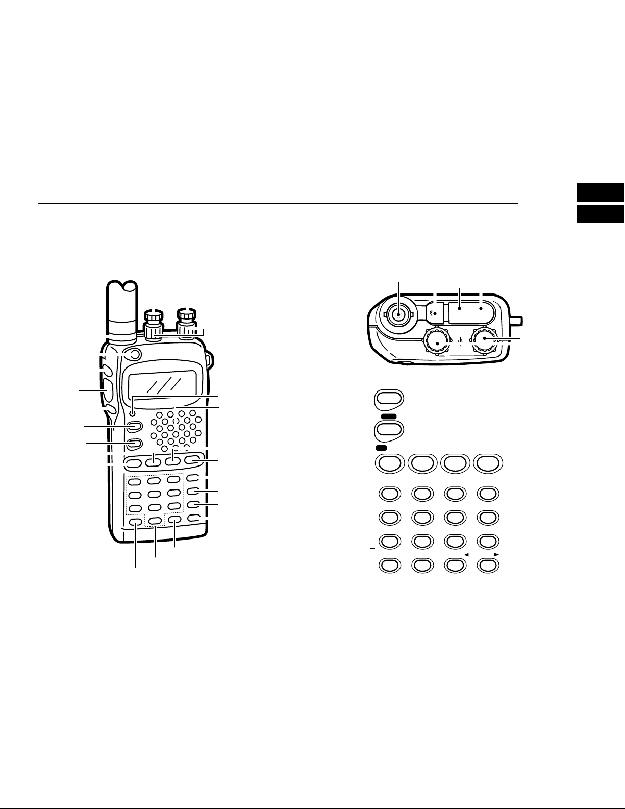
1 PANEL DESCRIPTION .................. 1–7
■Switches,controls, keysand
connectors .......................................1
■Functiondisplay ...............................6
2 BATTERY PACKS AND
ACCESSORIES ........................... 8–11
■Battery pack charging ...................... 8
■Chargingprecautions .......................8
■About the battery pack ...................... 8
■Chargingconnections ......................9
■Battery case ................................... 10
■Accessory attachment .................... 11
3 FREQUENCY AND CHANNEL
SETTING ................................... 12–16
■PowerON .......................................12
■VFOandmemory/call channels ..... 12
■Mainbandselection .......................13
■Operatingband selection ............... 13
■Frequency or channel selection
viathekeypad ................................ 14
■Usingthetuningdial .......................15
■Lockfunction .................................. 15
■Settingtuningdialincrements ........16
4 BASIC OPERATION .................. 17–18
■Receiveand transmit ......................17
5 REPEATER OPERATION .......... 19–21
■General ..........................................19
■Subaudibletones ........................... 20
■Offsetfrequency .............................20
■Autorepeaterfunction ....................21
6
MEMORY/CALL PROGRAMMING
.22–25
■General ..........................................22
■Programming during selection ........ 22
■Programmingafter selection .......... 23
■Memory edit (transferring) .............. 23
■Memory names .............................. 24
■Memory clear ................................. 25
7 DTMF MEMORY ........................ 26–27
■Programminga DTMF code ........... 26
■Transmitting a DTMF code ............. 27
■DTMFtransmissionspeed ............. 27
8 SCAN OPERATION ................... 28–31
■Scantypes .....................................28
■Full/programmedscan ................... 29
■Memory scan ................................. 29
■Skipchannelsetting .......................30
■Scanresumecondition ...................30
■Frequency skip function ................. 31
9
SUBAUDIBLE TONE OPERATION
.32–33
■Tone squelch operation .................. 32
■Tone scan .......................................33
■Pocketbeep operation ....................33
10 OTHER FUNCTIONS ................. 34–38
■Guidefunction ................................34
■Battery voltage indication ............... 34
■Autopower-offfunction ................... 35
■Functiondisplaybacklighting .........35
■Powersaver ................................... 36
■LCDcontrast ..................................36
■OptionalHM-75Afunctions ............37
■Handheld-to-handheldcloning .......38
■Partial reset .................................... 38
■Allreset ..........................................38
11 TROUBLESHOOTING ...................... 39
12 MODE ARRANGEMENT ........... 40–41
13 SPECIFICATIONS ............................ 42
14 OPTIONS .......................................... 43
TABLE OF CONTENTS

PANEL DESCRIPTION 1
1
qAntenna
connector
w[POWER]
o[VFO]
y[MAIN]
u[BAND]
i[MR]
e[SQL]
r[PTT]
t[L/G]
!1 DIGIT KEYS
!0 [.]
!2
!3 [M•N]
!4
!5 [TONE]
!6 [H/L]
!7 [S.MW]
!8 [CALL]
!9 Battery pack
release
@0 Speaker/
microphone
@1 [TX/RX]
@2 [VOL]
@3 [DIAL]
VOL
DIAL
SP MIC
DC13.5V
+
–
@3
q@4@5
■Switches, controls, keys and connectors
BAND
CHNGCHNG
MAIN
SCAN
D
T
M
F
VFO
CLRCLR MHz
1
QZ
4
GHI
7
PRS
DTMF•M
•
M
MR
SKIP
CALL
LOCK
S.MW
MW
Symbol
0M•N
MN•W
D
C
TONE
DUP K
B
H/L
SET J
A
2
ABC 3
DEF
5
JKL 6
MNO
8
TUV 9
WXY
T SCAN
#
!1
!0 !2
!3
!4
!5
!6
!7
!8i
o
u
y

1PANEL DESCRIPTION
2
yMAIN KEY [MAIN (SCAN) (DTMF)]
➥Push to toggle the main band assignment. (p. 13)
➥Starts and stops a scan when pushed for 2 sec.
(p. 29)
➥While pushing [PTT], this key transmits the se-
lected DTMF memory contents. (p. 26)
uBAND KEY [BAND (CHNG)]
➥Push to select the operating band (VHF, UHF,
etc.) or deactivation. (p. 13)
•For VHF display, 144 MHz band, 430(440) MHz band,
avionics band*1and weather channels*2can be se-
lected.
*1U.S.A. and Asia versions only
*2U.S.A. version only
•For UHF display, 144 and 430(440) MHz bands can be
selected.
➥Enters the band arrangement condition to ex-
change the VHF and UHF displays when pushed
at turning power ON. (p. 13)
iMEMORY MODE KEY [MR (SKIP)]
➥Push to select memory mode. (p. 22)
➥While in memory mode, push this key for 2 sec.
to toggle the selected memory channel between
a skip and non-skip channel. (p. 30)
MR
SKIP
BAND
CHNGCHNG
MAIN
SCAN
D
T
M
F
qANTENNA CONNECTOR (p.11)
Connects the supplied antenna.
wPOWER SWITCH [POWER] (p.12)
Push and hold for 2 sec. to toggle the transceiver power
ON and OFF.
eSQUELCH SWITCH [SQL] (p. 17)
➥Push to open the main band’s squelch and monitors the
operating frequency.
➥Set the squelch level while pushing this key and rotating
the tuning dial.
rPTT SWITCH [PTT] (p.17)
Push and hold to transmit; release to receive.
tLIGHT/GUIDE SWITCH [L/G]
➥Activates the display and keypad backlighting for 5 sec.
•The backlighting can be set as manual ON/OFF, automatic
ON/OFF and automatic OFF with 5 sec. timer (default) using
initial set mode. (p. 35)
➥Shows a quick description of a key’s function when
pushing this key and the desired key. (p. 34)
•In set mode, the quick description automatically appears when
pausing an operation for 5 sec.

1
PANEL DESCRIPTION
3
oVFO MODE KEY [VFO (CLR) (MHz)]
➥Push this key to cancel most functions, then push
again to select VFO mode. (p. 12)
•When making a mistake during digit input, push this
key to cancel and start from the beginning.
➥Selects 1 MHz tuning step when pushed for 2
sec. in VFO mode. (p. 16)
➥Partially resets the VFO frequencies, VFO set-
tings and set mode settings when pushed at turn-
ing power ON. (p. 38)
!0 DECIMAL POINT KEY [•(DTMF•M) (M)]
➥In VFO mode, push to enter the operating fre-
quency from the 100 kHz digit. (p. 14)
➥Push this key for 2 sec. to enter DTMF memory
mode, then push again for 2 sec. to program the
DTMF memory. (p. 26)
➥While pushing [PTT], this key sends a DTMF “E”
(M).
!1 DIGIT KEYS
➥Input the specified digit during frequency input, memory
channel selection, etc.
➥Transmit the DTMF code of the specified digit while push-
ing [PTT].
DTMF•M
•
M
VFO
CLRCLR MHz
➥For the [1]–[5] and [0] keys, select scan edges during full/
programmed scan.
•Push [1]–[5] to select scan edges “1A/1B”–“5A/5B,”respectively.
•Push [0] to select full scan.
➥In addition, each key has character input for memory or
DTMF memory names (characters are assigned to keys
using the same convention as for telephones). (pgs. 24, 26)
!2 TONE SCAN KEY [T SCAN (ΩΩ) (#)]
➥Push this key for 2 sec. to start the tone scan.
(p. 33)
➥While programming memory channels or DTMF
memory names, this key moves the cursor back-
ward.
➥While pushing [PTT], this key sends a DTMF “F”
(#).
!3 MEMORY NAME KEY [M•N (MN•W) (≈≈)]
➥Push to toggle between frequency and name in-
dications. (p. 24)
➥While programming memory channels or DTMF
memory names, this key moves the cursor for-
ward.
➥While pushing [PTT], this key sends a DTMF “D.”
M•N
MN•W
D
T SCAN
#

1PANEL DESCRIPTION
4
!4 C KEY [C]
While pushing [PTT], this key sends a DTMF “C.”
!5 TONE/DUPLEX KEY [TONE (DUP) (K)]
➥Push this switch to activate the following functions
in order (pgs. 19, 32).
•Subaudible tone encoder—“T”appears.
•Pocket beep—“TSQLS”appears.
•Tone squelch—
“TSQL”appears.
•No tone operation—no indicator appears.
➥Push this key for 2 sec. to select semi-duplex or
simplex operation. (p. 19)
•“–DUP”appears during minus duplex operation,
“DUP”appears during plus duplex operation and no
indicator appears during simplex operation.
➥While pushing [PTT], this key sends a DTMF “B.”
!6 OUTPUT POWER/SET MODE KEY [H/L (SET) (J)]
➥Push this key to toggle between high and low out-
put power. (p. 17)
➥Push this key for 2 sec. to enter set mode. (p. 41)
➥Enters initial set mode when pushed at power
ON. (p. 41)
➥While pushing [PTT], this key sends a DTMF “A.”
H/L
SET J
A
TONE
DUP K
B
C
!7 SELECT MEMORY WRITE KEY [S.MW (MW)]
➥Push this key to select the desired memory chan-
nel number to be programmed. (p. 22)
•“M”and memory channel number flash and the [DIAL]
can be used for channel selection.
➥Push this key for 2 sec. to write the displayed fre-
quency and information into the selected memory
channel (or VFO, call channel). (p. 22)
➥Push then push and hold this key while in mem-
ory select mode to erase the contents of the se-
lected memory channel. (p. 25)
!8 CALL MODE KEY [CALL (LOCK)]
➥Push this key to select the call channel. (p. 12)
➥Push this key for 2 sec. to toggle the lock function
ON and OFF. (p. 15)
•“ ”appears while the lock function is activated.
•[POWER], [VOL], [SQL], [PTT], [L/G] and [H/L] can still
be accessed while the lock function is ON.
➥While pushing [PTT], push this key for 1 to 2 sec.
to transmit a 1750 Hz tone burst for repeater ac-
cess. (Eur., U.K. and Italy versions only; p. 19)
!9 BATTERY PACK RELEASE (p. 10)
Push to open the latch for battery pack removal.
@0 SPEAKER/MICROPHONE
CALL
LOCK
S.MW
MW

1
PANEL DESCRIPTION
5
@1 TX/RX INDICATOR [TX/RX] (p. 17)
Lights green while receiving a signal or when the squelch
is open; lights red while transmitting; lights orange during
crossband full duplex operation.
@2 VOLUME CONTROLS [VOL] (p.17)
Rotate [VOL] to adjust the audio level.
@3 TUNING DIALS [DIAL]
➥Rotate [DIAL] to set operating frequencies, memory
channels, set mode contents, etc. (p. 15)
➥While pushing [SQL], this dial sets the squelch level.
(p. 17)
➥While pushing [BAND], this dial sets the operating band.
(p. 13)
@4 EXTERNAL SPEAKER AND MICROPHONE JACKS
[SP/MIC]
Connect an optional speaker-microphone or headset, if de-
sired. The internal microphone and speaker will not func-
tion when either is connected. (See p. 43 for a list of
available options.)
DExternal connection
@5 EXTERNAL DC POWER JACK [DC13.5V]
Allows operation with a 13.5 V DC power source using the
optional cables, CP-12/L or OPC-254/L.
CAUTION:Operation with an external DC power
source simultaneously charges batteries inside the bat-
tery case or the battery pack. When using dry cell bat-
teries this may cause battery leakage and damage the
transceiver; when using a Ni-Cd battery pack this may
cause battery overcharging and shorten the life of the
battery pack.
The above connection does not apply when a
condensor microphone is connected.
Remote Audio out
(8 Ω)
[SP]
MIC
3.5 V
PTT
[MIC] Audio input
PTT
33 kΩ(2 kΩ)

1PANEL DESCRIPTION
6
LOW
TSQL
DUP
MAIN MAIN
S
GUIDE
75
50
25LOW
75
50
25
TSQL
DUP
S
qq
w
e
t
r
w
uui
o!0
y
e
t
r
y
■Function display
qMAIN BAND INDICATORS (p. 13)
Appear above the frequency which is selected as the main
band.
•Only one of these indicators appears at a time.
wFREQUENCY READOUTS
Show the operating frequency, set mode contents, etc.
•The frequency on the left and right can be exchanged. (p. 13)
•The smaller “75,”“50”and “25”to the right of each readout indi-
cate 7.5, 5.0 and 2.5 kHz, respectively.
•The decimal point of the frequency flashes during scan. (p. 29)
•While operating in the avionics band, a colon appears to indicate
AM mode. (U.S.A. and Asia versions only)

1
PANEL DESCRIPTION
7
eLOW POWER INDICATORS (p.17)
Appear when low output power is selected.
rS/RF INDICATORS (p. 17)
➥Show the relative signal strength while receiving.
➥Show the output power selection while transmitting.
tTONE INDICATORS (pgs.19, 32)
“T”appears when the subaudible tone encoder is in use;
“TSQLS”appears during pocket beep operation and
“T SQL”appears when the tone squelch function is acti-
vated.
yDUPLEX INDICATORS (p. 19)
Appear when semi-duplex operation (repeater operation)
is in use.
•“–DUP”appears when minus duplex is selected; “DUP”only, ap-
pears when plus duplex is selected.
uSKIP INDICATORS
➥Appear when a selected memory channel is set as a
skip channel. (p. 30)
•Skip channels are not detected (ignored) during memory
scan.
➥Flash during full/programmed scan when the frequency
skip function is activated. (p. 31)
iALPHANUMERIC READOUT
➥Shows the selected memory channel number in mem-
ory mode.
•Memory name can be selected instead of channel numbers.
(p. 24)
➥Shows guide (or description) when the [L/G] and desired
keys are pushed, or no key operation is performed for 5
sec. in set mode, during name programming, etc. (p. 34)
oLOCK INDICATOR (p. 15)
Indicates that the lock function is in use.
!0 QUICK GUIDE INDICATOR (p.34)
Appears when the quick guide function is activated.

BATTERY PACKS AND ACCESSORIES
2
8
■Battery pack charging
The supplied* BP-173 or BP-180
BATTERY PACK
includes
rechargeable Ni-Cd batteries and can be charged approx.
300 times. Charge the battery pack before first operating the
transceiver or when the battery pack becomes exhausted.
*Optional for versions which come with the BP-170
BATTERY CASE
.
If you want to be able to charge the battery pack more than
300 times, the following points should be observed:
1.Avoid overcharging. The charging period should be less
than 48 hours.
2.Use the battery until it becomes almost completely ex-
hausted under normal conditions. We recommend battery
charging just after transmitting becomes impossible.
■Charging precautions
NEVER attempt to charge dry cell batteries. This will cause
internal liquid leakage and damage the battery case and
transceiver.
NEVER connect two or more chargers at the same time.
Charging may not occur under temperatures of 10°C (50°F)
or over temperatures of 40°C (104°F).
■About the battery pack
DOperating period
Depending on the attached battery pack, the operating period
of the transceiver varies. Refer to p. 43 for battery pack spec-
ifications.
DBattery pack life
If your battery pack seems to have no capacity even after
being fully charged, completely discharge it by leaving the
power ON overnight. Then, fully charge the battery pack
again.
If the battery pack still does not retain a charge (or very little),
a new battery pack must be purchased.
DRecycling information (U.S.A. only)
The product that you have purchased contains a
rechargeable battery. The battery is recyclable. At
the end of its life, under various state and local
laws, it may be illegal to dispose of this battery into
the municipal waste stream. Call 1-800-8-BATTERY for bat-
tery recycling options in your area or contact your dealer.
RBRC
RBRC
Ni-
Cd

2
BATTERY PACKS AND ACCESSORIES
9
■Charging connections
DRegular charging
Attach the supplied* or optional battery pack; then, connect
the supplied* wall charger via an AC outlet as shown below.
*Optional for versions which include a battery case.
To [DC13.5V]
Wall charger
Any battery
pack
attached to
transceiver
Check orientation
for correct
charging
BP-171 or BP-172
without transceiver
BP-173 or
BP-180
Packed
together
as the
AD-51
(optional)
AD-51B
BC-119 + AD-75
(optional)
AD-51A
Charging periods:
1 hour (w/BP-171
or BP-180)
1.5 hours (w/BP-172 or BP-173)
Charging periods:
15 hours (w/BP-171, BP-173 or BP-180)
20 hours (w/BP-172)
DRapid charging with the BC-119
qInsert the AD-51A into the charging slot of the BC-119.
•The AD-75 may be additionally necessary if the BC-119 contains
no connection terminals.
wInsert the AD-51B into the groove in the AD-51A (front-fac-
ing side of the AD-51A) observing the proper orientation.
eInsert the battery pack, either by itself or attached to the
transceiver, into the AD-51A.

2BATTERY PACKS AND ACCESSORIES
10
DOperation with an optional cable
Connect an optional charger or cable to the transceiver as il-
lustrated below. Be careful of battery overcharging as the con-
nected battery is charged simultaneously.
CAUTION:Remove dry cell batteries from the BP-170
BAT
-
TERY CASE
when using the [DC13.5V] jack.
■Battery case
When using a battery case attached to the transceiver, install
4 AA(R6) size alkaline batteries as illustrated below.
Open the case.
Remove the case
from the transceiver.
Install 4 AA(R6) size dry
cell batteries into the
battery case.
CP-12
(optional)
OPC-254
(optional)
To a 12 V cigarette
lighter socket
To a 4.5 to 16 V DC
power source
To [DC13.5V]
white +
black _

DAntenna
Insert the supplied antenna into the an-
tenna connector and rotate the antenna
as shown in the diagram below.
Keep the jack cover attached when
jacks are not in use to avoid bad con-
tacts.
DBelt clip
Remove screws, then attach the belt
clip using the same screws. Conve-
niently attaches to your belt.
DHandstrap
Attach the handstrap as shown in the
diagram below. Facilitates carrying.
2
BATTERY PACKS AND ACCESSORIES
11
■Accessory attachment
CAUTION:
Transmitting
without the
antenna may
damage the
transceiver.

■Power ON
qCharge the battery pack or
install alkaline batteries into
the battery case. (pgs. 9,
10)
wPush and hold [POWER]
for 2 sec. to turn power ON.
•Remaining battery voltage is
displayed for 2 sec. (p. 34)
•The display shows the approx. voltage
in 0.5 V steps.
•When the battery voltage is lower than
4.5 V, “LOW V”appears. Charge the
battery pack or place new dry cells in
the battery case in this case.
•If “OVER V”appears, UNPLUG the ex-
ternal DC plug immediately. Connected
voltage is over 16 V and could damage
the transceiver.
FREQUENCY AND CHANNEL SETTING
3
12
■
VFO and memory/call channels
This transceiver has 2 normal operating modes: VFO mode
and memory mode.
VFO mode is used for setting a desired frequency within the
band range.
➥Push [VFO] to select VFO mode.
Memory (call) mode is used for operation of memory (call)
channels which have programmed frequencies.
➥Push [MR] to select memory
mode.
•To program a memory, refer to p. 22.
➥Push [CALL] to select a call chan-
nel.
What is VFO?
VFO is an abbreviation of Variable Frequency Oscillator.
Frequencies for transmitting and receiving are generated and
controlled by the VFO.
MAIN
MAIN
“M”(or a memory name)
appears.
MAIN
“C,”“VHF CALL”or
“UHF CALL”appears.
Push for
2 sec.
for 2 sec.
POWER
after 2 sec.
MAIN
MAIN

3
FREQUENCY AND CHANNEL SETTING
13
■Main band selection
This transceiver can receive 2 band signals simultaneously.
To change frequency or to activate a function, you must des-
ignate a band, VHF or UHF, as the main band. All switches
affect the designated main band only.
•“Q”appears above the main band.
■Operating band selection
The VHF display can also receive UHF, avionics band*1and
VHF weather channels.*2The UHF display can also receive
VHF band signals. Using this capability, the transceiver can
receive 2 frequencies simultaneously on either the VHF or
UHF band. In addition, a display can be turned OFF to use
the transceiver as a mono band transceiver.
qSelect the desired
band with [MAIN].
wPush [BAND] several
times to select the de-
sired band.
•“--- --”appears when
the display is OFF.
•Rotating [DIAL] while
pushing [BAND] also
selects the display.
*1 U.S.A. and Asia versions only *2 U.S.A. version only
DExchanging the displays ]
VHF and UHF displays can be ex-
changed at power ON if desired. The
right and left displays are used for
VHF and UHF, respectively, by de-
fault.
qTurn power ON while pushing [(BAND)CHNG] to enter band
arrangement condition.
wRotate [DIAL] to select the displays.
ePush [VFO] to program the display selection.
rTurn power OFF to exit band arrangement condition.
NOTE:
•VHF and UHF memory channels are called up from the
respective operating band, regardless of left/right displays.
•5 kHz tuning steps cannot be selected in the VHF display
when both displays are set for the UHF band.
•The sub band is muted when crossband full duplex is de-
activated and the main band is transmitting.
•The sub band is muted under the following conditions
even when crossband full duplex is activated:
- Both displays show the same band.
-
Sub band is the avionics band and main band is VHF transmission.
- Sub band is a weather channel and main band is UHF trans-
mission.
MAIN MAIN
BANDBAND
MAIN
*2
*1

3FREQUENCY AND CHANNEL SETTING
14
[EXAMPLE]: Setting the frequency to 145.360 MHz.
■Frequency or channel selection via the keypad
D
Frequency
qAssign the main band to the desired display with [MAIN].
wSelect VFO mode with [VFO].
ePush 6 digit keys to input a frequency.
•Push [•] to input the frequency starting from the 100 kHz digit.
•When a digit is mistakenly input, push [(VFO)CLR] and input from
the beginning.
•“0,”“2,”“5”and “7”are acceptable for the 1 kHz digits (depending
on the 10 kHz digit).
•Any frequency in the receive frequency range can be selected,
regardless of the operating band.
DMemory channels
qAssign the main band to the desired display with [MAIN].
wSelect memory mode with [MR].
ePush 2 digit keys to select the desired memory channel.
•The first ten memory channels (00–09) are preceded by a “0.”
•To select scan edge channels, 1A to 5B, use [•(M)(DTMF•M)] for
“A”and [#(T SCAN)] for “B.”
•Only programmed memory channels can be selected.
[EXAMPLE]: Selecting memory channel 43 (when channel 43 is already programmed).
MAIN MAIN MAIN MAIN
MR 4 3
MAIN MAIN MAIN MAIN MAIN
Decimal point appears.
VFO 1 04 5 3 6

3
FREQUENCY AND CHANNEL SETTING
15
■Using the tuning dial
DFrequency
qAssign the main band to the desired display with [MAIN].
wSelect VFO mode with [VFO].
eRotate the main band’s [DIAL] to change the frequency.
•The frequency changes according to the preset tuning steps.
See the next page for setting tuning steps.
•Push [(VFO)MHz] for 2 sec. then rotate [DIAL] to change the fre-
quency in 1 MHz steps. Push [VFO] again to return to regular
tuning steps.
DMemory channels
qAssign the main band to the desired display with [MAIN].
wSelect memory mode with [MR].
eRotate the main band’s [DIAL] to change the indicated
memory channel.
•Only programmed memory channels can be selected.
MAIN
75
50
25
MAIN
[DIAL] changes the frequency
according to the selected tuning step.
After pushing [(VFO)MHz] for 2 sec.,
[DIAL] changes the frequency in 1 MHz
steps.
■Lock function
The lock function prevents accidental frequency changes and
accidental function access.
➥Push [(CALL)LOCK] for 2 sec. to toggle the lock function ON
and OFF.
•“ ”appears while the lock function is activated.
•[POWER], [VOL], [SQL], [PTT], [L/G] and [H/L] can still be ac-
cessed while the lock function is ON.
MAIN
Appears when the
lock function is in use.

3FREQUENCY AND CHANNEL SETTING
16
■
Setting tuning dial increments
DTuning step selection [
Tuning steps can be selected for each band. This transceiver
has 8 tuning steps as follows:
•5 kHz* •10 kHz •12.5 kHz •15 kHz
•20 kHz •25 kHz •30 kHz •50 kHz
*5 kHz cannot be selected in the VHF display when both displays are
set for the UHF band.
qAssign the main band to the de-
sired display with [MAIN].
wSelect VFO mode with [VFO].
ePush [(H/L)SET] for 2 sec. to enter
set mode.
rPush [(H/L)(SET)J] or [(TONE)K]
several times until “TS”appears.
•Previously selected tuning step ap-
pears.
tRotate the main band’s [DIAL] to
select the desired tuning step.
yPush [(VFO)CLR] to set the se-
lected tuning step.
NOTE:Both displays have independent tuning steps ac-
cording to the operating band. (e.g. VHF band in left dis-
play: 5 kHz step; VHF band in right display: 12.5 kHz step)
DUsing 1 MHz tuning step
This transceiver has a 1 MHz tuning step for quick frequency
setting.
qAssign the main band to the desired display with [MAIN].
wSelect VFO mode with [VFO].
ePush [(VFO)MHz] for 2 sec. to select the 1 MHz tuning step.
•The digits below 100 kHz disappear.
rRotate the main band’s [DIAL] to change the frequency in
1 MHz steps.
tPush [(VFO)CLR] to cancel the 1 MHz tuning step and to
return to the previous tuning step.
MAIN
100 kHz digit and below disappear.
MAIN
MAIN
12.5 kHz tuning step
(VHF)
25 kHz tuning step
(UHF)
Other manuals for IC-W32A
1
This manual suits for next models
1
Table of contents
Other Icom Transceiver manuals