ICON IP FREEMOTION EPIC GZFI8136.2 User manual

CAUTION
Read all precautions and instruc-
tions in this manual before using
this equipment. Save this manual
for future reference.
Model No. GZFI8136.2
Serial No.
Write the serial number in the
space above for future reference.
QUESTIONS?
At FreeMotion Fitness, we are
committed to providing com-
plete customer satisfaction. If
you have questions, see HOW
TOCONTACT CUSTOMER
CARE on the back cover of this
manual.
Visit our website at
www.proform.com
new products, prizes,
fitness tips, and much more!
Visit our website at
www.healthrider.com
new products, prizes,
fitness tips, and much more!
Visit our website at
www.nordictrack.com
new products, prizes,
fitness tips, and much more!
Visit our website at
www.weiderfitness.com
new products, prizes,
fitness tips, and much more!
Visit our website at
www.freemotionfitness.com
Serial Number Decal (inside tower)
OWNER’S
MANUAL

2
IMPORTANT PRECAUTIONS . . . . . . . . . . . . . . . . . . . . . . . . . . . . . . . . . . . . . . . . . . . . . . . . . . . . . . . . . . . . . . . . 3
WARNING DECAL PLACEMENT . . . . . . . . . . . . . . . . . . . . . . . . . . . . . . . . . . . . . . . . . . . . . . . . . . . . . . . . . . . . . .4
BEFORE YOU BEGIN . . . . . . . . . . . . . . . . . . . . . . . . . . . . . . . . . . . . . . . . . . . . . . . . . . . . . . . . . . . . . . . . . . . . . . 5
ADJUSTMENT . . . . . . . . . . . . . . . . . . . . . . . . . . . . . . . . . . . . . . . . . . . . . . . . . . . . . . . . . . . . . . . . . . . . . . . . . . . . 6
MAINTENANCE AND TROUBLESHOOTING . . . . . . . . . . . . . . . . . . . . . . . . . . . . . . . . . . . . . . . . . . . . . . . . . . . .7
CABLE DIAGRAM . . . . . . . . . . . . . . . . . . . . . . . . . . . . . . . . . . . . . . . . . . . . . . . . . . . . . . . . . . . . . . . . . . . . . . . . .11
PART LIST . . . . . . . . . . . . . . . . . . . . . . . . . . . . . . . . . . . . . . . . . . . . . . . . . . . . . . . . . . . . . . . . . . . . . . . . . . . . . .13
EXPLODED DRAWING . . . . . . . . . . . . . . . . . . . . . . . . . . . . . . . . . . . . . . . . . . . . . . . . . . . . . . . . . . . . . . . . . . . .14
HOW TO CONTACT CUSTOMER CARE . . . . . . . . . . . . . . . . . . . . . . . . . . . . . . . . . . . . . . . . . . . . . . .Back Cover
TABLE OF CONTENTS
FREEMOTION is a registered trademark of ICON IP
,Inc.

3
1. Before beginning this or any exercise pro-
gram, consult your physician. This is espe-
cially important for persons over the age of
35 or persons with pre-existing health prob-
lems.
2. Use the strength equipment only as
described in this manual.
3. It is the responsibility of the owner to ensure
that all users of the strength equipment are
adequately informed of all precautions, have
read and understood all warning and caution
labels, and are informed of how to use the
strength equipment properly.
4. Keep the strength equipment indoors, away
from moisture and dust. Do not put the
strength equipment in a garage or covered
patio, or near water.
5. Use the strength equipment only on a level
surface. Cover the floor beneath the strength
equipment to protect the floor.
6. It is the purchaser’s responsibility to ensure
that there is enough space around the
strength equipment for the intended exer-
cise. Do not crowd the strength equipment.
7. Anchor the strength equipment to the floor
with the anchor strap where required or
whenever possible to provide maximum sta-
bility.
8. Keep children under age 12 and pets away
from the strength equipment at all times.
9. The strength equipment is designed to sup-
port a maximum user weight of 350 lbs. (159
kg).
10. Always wear athletic shoes for foot protec-
tion while exercising.
11. Keep hands and feet away from moving
parts. Do not lean on or rest your hands on
the strength equipment when it is in use.
12. Check all cables, cable connections, and
pulleys before each use of the strength equip-
ment. Make sure that all parts are properly
tightened. Replace any worn parts immediate-
ly.
13. All users of the strength equipment should
be instructed to report any injury or strength
equipment irregularity to facility staff imme-
diately.
14. Make sure that the weight pin is completely
inserted into one of the weights.
15. Make sure that the cable remains on the pul-
leys at all times. If the cable binds while you
are exercising, stop immediately and make
sure that the cable is on the pulleys and that
nothing is interfering with the cable or the
pulleys. Replace the cable at least every two
years.
16. If you feel pain or dizziness at any time while
exercising, stop immediately and begin cool-
ing down.
WARNING: To reduce the risk of serious injury, read all important precautions and instruc-
tions in this manual and all warnings on the strength equipment before using the strength equipment.
FreeMotion Fitness assumes no responsibility for personal injury or property damage sustained by or
through the use of this product.
IMPORTANT PRECAUTIONS

WARNING DECAL PLACEMENT
4
GZ7003
GZ7005
GZ7026
The decals shown below have been
applied in the indicated locations. If a
decal is missing or illegible, see HOW
TO CONTACT CUSTOMER CARE on the
back cover of this manual and order a
free replacement decal. Apply the
decal in the location shown.Note: The
decals may not be shown at actual size.
Decal 1
GZ7003
Decal 2
GZ7026
Decal 3
GZ7005
Decal 4
208842
Decal 2
Decal 4
Decal 3
Decal 1

Assembled Dimensions:
Height: 62 in. (157 cm)
Width: 70 in. (178 cm)
Depth: 40 in. (102 cm)
5
Base
Seat
Handle
Anchor Strap
Weights
Release Handle
Weight Pin
Backrest
Press Frame
Tower
BEFORE YOU BEGIN
Thank you for selecting the FREEMOTION®EPIC™
CALF EXTENSION strength equipment. The strength
equipment’s stylish ergonomic design and never-before-
seen features improve upon traditional strength training.
The innovative features and quality construction provide
areliable product for your club. And the advanced solu-
tions to isolating individual muscle groups make the
CALF EXTENSION strength equipment a key tool for
members to reach their goals.
For your benefit, read this manual carefully before
using the strength equipment. If you have questions
after reading this manual, see HOW TO CONTACT
CUSTOMER CARE on the back cover of this manual. To
help us assist you, please note the product model
number and serial number before calling. The model
number and the location of the serial number decal are
shown on the front cover of this manual.
Before reading further, please review the drawing below
and familiarize yourself with the parts that are labeled.

This section explains how to adjust the strength equipment. Make sure all parts are properly tightened each time
the strength equipment is used. Replace any worn parts immediately.
6
ADJUSTING THE RESISTANCE
To change the amount of resistance for your workout,
insert the weight pin into the desired weight. Make
sure that the weight pin is fully inserted into the
weight stack.
ADJUSTMENT
Weight
Stack
Weight
Pin
ADJUSTING THE SEAT
Squeeze the release handle to disengage the release
pin (not shown). Next, slide the seat to the desired
position. Then, release the release handle to engage
the release pin.
Release
Handle
Seat

7
MAINTENANCE AND TROUBLESHOOTING
For optimal performance of the strength equipment and to reduce the chances of injury to users, you must per-
form preventive maintenance on a regular basis. Instruct all personnel to perform the procedures described in
this section. Personnel must also record and report any accidents. To maintain the strength equipment’s warran-
ty, use only FREEMOTION EPIC parts for repair or replacement. If there are any questions or concerns, see
HOW TO CONTACT CUSTOMER CARE on the back cover of this manual.
DAILY MAINTENANCE
Upholstery and Frame—General Cleaning
1. Clean the strength equipment using a soft cloth
dampened with a light solution of mild soap and
warm water. If necessary, use a soft bristle brush
with the cleaning solution.
2. Rinse the area thoroughly using a soft cloth damp-
ened with clean water. Dry thoroughly.
Upholstery—Difficult Stains
1. Spray the stain with a non-abrasive household
cleaner such as FORMULA 409®cleaner, SIMPLE
GREEN®,or a similar product. Rub the stained
area gently and let the cleaning solution sit for a
few minutes.
2. Rinse the area thoroughly using a soft cloth damp-
ened with clean water.Dry thoroughly.
3. Repeat these steps if necessary using a soft bristle
brush.
Optional Method for Difficult Stains
1. Rub the stained area gently using a soft cloth
dampened with rubbing alcohol.
2. Rinse the area thoroughly using a soft cloth damp-
ened with clean water. Dry thoroughly.
CAUTION: When using any cleaning product, try it
first in an unnoticeable place to ensure that there is no
damage to the material. Follow the directions and the
safety precautions of the manufacturer of each clean-
ing product used. FreeMotion Fitness and its vendors
cannot be held liable for damage or injuries resulting
from the use or misuse of cleaning products.
Important: Do not use abrasive cleaners, which may
scratch the strength equipment. Strong cleaners and
abrasives will damage decals; use caution around
decals. Do not use solvents such as lacquer thinner,
kerosene, gasoline, or similar liquids.
WEEKLY MAINTENANCE
Hardware
Check all nuts and bolts and tighten them as required.
Important: All FREEMOTION EPIC cushions have
dense plywood supports with tee-nuts that are used to
bolt the cushions to the strength equipment. Because
the tee-nuts are held by the plywood, they will not
withstand the torque that standard nuts and bolts will.
When tightening the bolts securing a cushion, turn
them only until they are snug and the cushion does
not move or feel loose. Overtightening may strip the
tee-nuts from the plywood and make it impossible to
remove the cushion in the future.
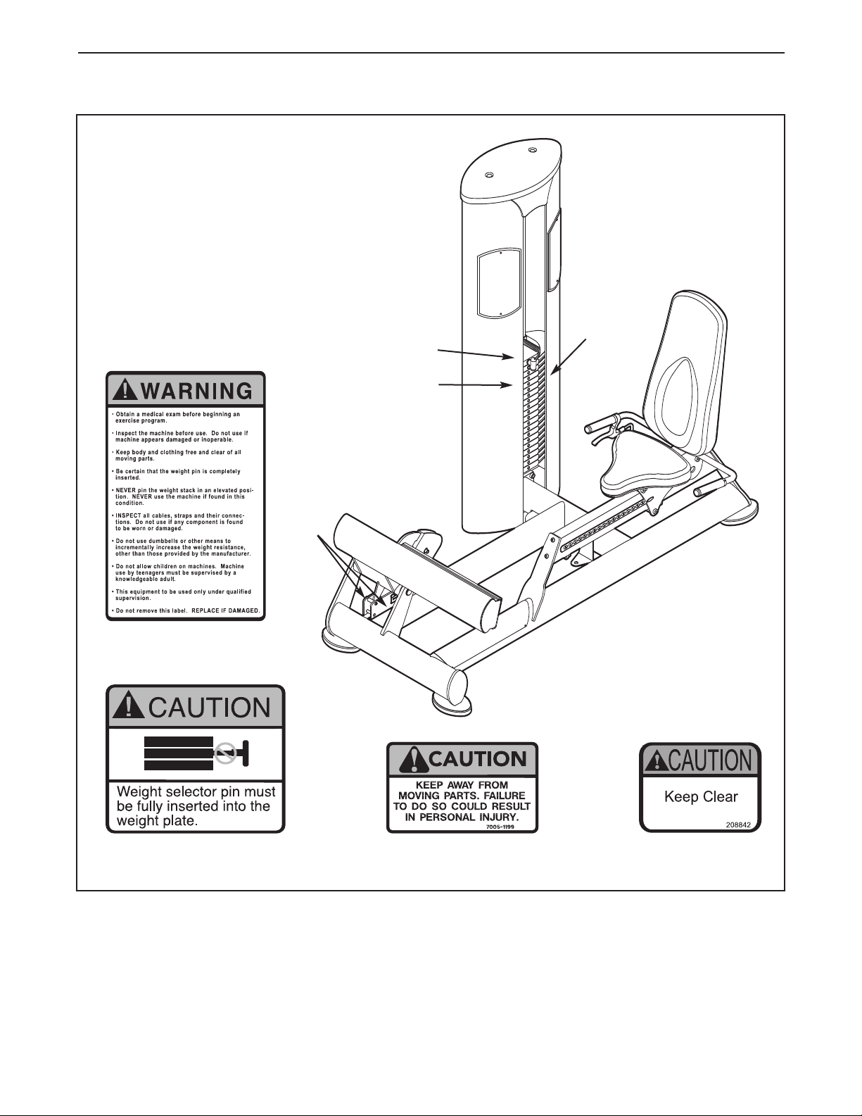
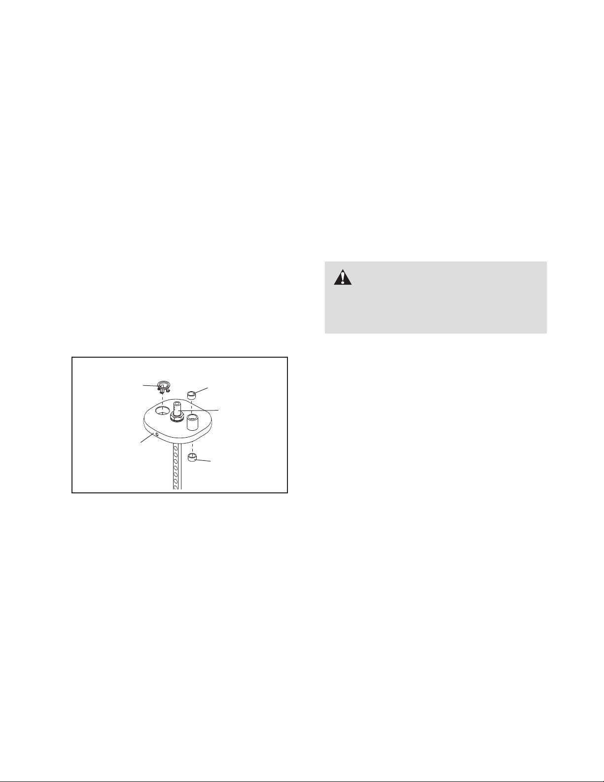
Cables
1. Check each cable for proper tension (see CABLE
ADJUSTMENT on page 8).
2. Check the entire length of each cable by slowly
performing one repetition on the strength equip-
ment; inspect the cable that is exposed on the
exterior of the strength equipment and the cable
inside the tower. Run your fingers along the cable,
paying close attention at the bends and attachment
points. Watch for the following conditions, which
may indicate a worn cable in need of replacement:
A. atorn or split cable sheath that exposes the
cable
B. a kinked or severely bent cable
C. a curled or twisted sheath
D. a stretched cable sheath, showing a thinning
cross-section
A
B
D
C

8
Cable Traps
Check the cable traps to ensure that they are not rub-
bing against the cables and that they are holding the
cables in the grooves of the pulleys. If a cable trap is
not correctly aligned, loosen the bolt slightly, readjust
the cable trap as necessary, and then retighten the
bolt.
MONTHLY MAINTENANCE
Grips
Check the grips and replace them if needed.
WEIGHT GUIDE LUBRICATION
Clean and lubricate the full length of each weight
guide by wiping it with a soft cloth containing a light-
weight motor oil, 10W-40 or 10W-30 weight. Apply
only a light coating over the entire length of the
weight guide. Do not use TEFLON®-based lubri-
cants.
CABLE ADJUSTMENT
For the strength equipment to function correctly, the
cable must be tensioned correctly. To check the ten-
sion of the cable, insert the weight pin into the top
weight. Next, slowly raise and lower the top weight by
performing one repetition. The top weight should
come to rest just on top of the next weight when the
repetition is completed.
If there is too much tension on the cable, the top
weight will not rest on the next weight, and it may be
difficult to insert the weight pin into the weights. If
there is not enough tension on the cable, the top
weight will not be lifted immediately when the repeti-
tion is begun. Ideally, the cable should not move more
than 1/2 in. (1.5 cm) from the resting position before
the top weight is lifted.
If there is too much tension or not enough tension on
the cable, adjust the cable as described in the follow-
ing steps.
Tower Pulley Adjustment
Tools required: 5/16" hex key, 9/16" open-end wrench
1. Lift the top weight off the
weight stack and insert the
weight pin into the next
weight and the sixth hole
from the top of the weight
selector.
2. Loosen the locknut attach-
ing the pulley to the bracket
in the top of the tower.
3. Move the pulley to the appropriate location in the
bracket. If more slack is needed in the cable,
move the pulley down. If less slack is needed in
the cable, move the pulley up.
4. Make sure that the cable trap is properly oriented
(see CABLE TRAPS at the left) and retighten the
locknut attaching the pulley to the bracket.
5. Lift the top weight and remove the weight pin.
Lower the top weight onto the next weight.
6. Readjust as necessary.
7. Slowly perform a repetition using a light load and
have someone make sure that the cable is not
derailed from a pulley or rubbing on a cable trap.
Correct Alignment
Incorrect Alignment
Rubbing Rubbing
Out of
Alignment
Traps Traps
Cable
Cable
Pulley
Locknut

9
Top Weight Adjustment
Tools required: 5/32” hex key
1. If the cable needs to be shortened 3/4 in. (2 cm)
ormore, follow the instructions in steps 1 and 2
on page 8; then, go to step 2 below.
2. Lift the coupler cover from the top weight coupler.
Loosen but do not remove the two set screws in
each side of the weight coupler.
3. Pull the cable out of the top weight coupler.
Determine the amount that the cable needs to be
shortened, and cut that much off the end of the
cable. The cable must be long enough to be
held by the set screws without lifting the top
weight.
4. Cut the cable to the desired length and strip 1 in.
(2.5 cm) of the vinyl sheath from the cut end of
the cable.
5. Insert the cable into the top weight coupler until all
four set screws can be tightened against the
cable. Tighten each set screw alternately 1/4 turn,
until all are set to 150 inch/pounds (17 Newton-
meters).
6. Lower the coupler cover over the top weight cou-
pler.
7. Slowly perform a repetition using a light load and
have someone make sure that the cable is not
derailed from a pulley or rubbing on a cable trap.
Press Frame Pulley Adjustment
Tools required: Adjustable wrench
1. Lift the top weight off the
weight stack and insert the
weight pin into the next
weight and the sixth hole
from the top of the weight
selector.
2. Loosen, but do not remove, the indicated nut.
3. To remove slack from the cable, move the pulley
(not shown) to the top of the indicated slot.
Toadd slack to the cable, move the pulley (not
shown) to the bottom of the indicated slot.
4. Retighten the nut.
5. Lift the top weight and remove the weight pin.
Lower the top weight onto the next weight.
6. Readjust as necessary.
7. Slowly perform a repetition using a light load and
have someone make sure that the cable is not
derailed from a pulley or rubbing on a cable trap.
Top
Nut
Slot
Pulley
Bottom
Set Screws
Cable
Top Weight
Coupler
Coupler Cover

10
WEIGHT STACK SERVICING
Servicing the weight stack involves replacing the two
guide bushings and the weight insert in the top weight.
Toorder these parts, see HOW TO CONTACT CUS-
TOMER CARE on the back cover of this manual.
1. Remove the wingnuts under the tower cap and
remove the tower cap from the tower.
2. Remove the nuts and washers from the tops of the
weight guides.
3. Lift the coupler cover on the end of the cable, and
loosen the four set screws—this will release the
cable.
4. Lift the weight guides out of the top of the tower.
5. Remove the nut, star washer, and washer from the
top of the weight selector. Lift and rotate the top
weight, and remove it through the front opening of
the tower.
6. Use a punch to drive the two existing guide bush-
ings and the weight insert out of the top weight.
7. Hold one of the new guide bushings square to the
face of one of the holes in the top weight, place a
protective piece of wood on top of the guide bush-
ing, and lightly tap the guide bushing until it is flush
with the surface. Insert the other guide bushing
and the weight insert in the same way.
8. Replace the top weight. Next, tighten the nut, star
washer, and washer onto the weight selector.
9. Reattach the cable to the top weight coupler.
Retighten the four set screws into the threaded
holes. Tighten the set screws equally until they
contact the cable. Then, tighten each screw alter-
nately 1/4 turn, until all are set to 150 inch/pounds
(17 Newton-meters).
10. Clean and lubricate the weight guides by wiping
them with a soft cloth containing a lightweight motor
oil, 10W-40 or 10W-30 weight. Apply only a light
coating over the entire length. Do not use
TEFLON®-based lubricants.
11. Reinsert the weight guides through the top of the
tower and into the weight stack. Note: If the weight
stack has shifted, use a short bar to realign the
holes in the weights. Hold the weights while insert-
ing the weight guides.
12. Reattach the weight guides to the top of the frame
with the two nuts and washers.
13. Insert the weight pin into the top weight. Slowly per-
form a repetition, lifting the top weight as far as
possible. Then, slowly lower the top weight. If the
top weight sticks, loosen one of the nuts. Slowly
perform another repetition. Retighten the nut.
Check the full travel again and readjust as neces-
sary.
14. Slowly perform a repetition using a light load and
have someone make sure that the cable is not
derailed from a pulley or rubbing on a cable trap.
15. Replace the tower cap and retighten the wingnuts
onto the bolts.
Weight
Insert
Guide
Bushing
Guide
Bushing
Top Weight
Top Weight
Coupler
WARNING: Do not force the
weight guides into the weights; doing so
will damage the bushings and the weight
inserts.

11
CABLE DIAGRAM
The cable diagram shows the proper route of the
cable. Use the diagram to make sure that the cable
and the cable traps have been assembled correctly.
Ifthe cable has not been correctly routed, the
strength equipment will not function properly and
damage may occur. The numbers show the correct
route of the cable. Make sure that the cable traps
do not touch or bind the cable.
1
6
3
4
5
7
49
2
Do not tighten the
Set Screws (49) more
than 150 inch/pounds
(17 Newton-meters).

12
NOTES

13
Key No. Qty. Description Key No. Qty. Description
1 1 Base
2 1 Seat Frame
3 1 Backrest Frame
4 1 Press Frame
5 1 Foot Plate
6 1 Tower
7 1 Base Cover
8 1 Backrest
9 1 Seat
10 1 Tower Cap
11 1 Cover
12 3 Base Foot
13 1 Long Plate Frame
14 1 Short Plate Frame
15 1 Short Panel
16 1 Long Panel
17 19 20-lb. Weight
18 1 Top Weight
19 2 Weight Guide
20 2 Trim
21 4 Tower Foot
22 1 Base Cap
23 1 Anchor Strap
24 1 Weight Pin
25 2 Foam Grip
26 2 Handle Collar
27 1 Release Handle
28 1 Release Cable
29 2 Weight Bumper
30 2 Handle Endcap
31 1 Press Frame Axle
32 2 Bearing
33 3 Nylon Spacer
34 4 1/4" Set Screw
35 3 3/8" Fine Nut
36 6 1" Non-patch Bolt
37 1 Weight Rod
38 2 Snap Ring
39 1Cable
40 1 Cable End
41 2Cable Bushing
42 5 Pulley
43 2 1" Nylon Washer
44 1Coupler Cover
45 1 1" Nut
46 1 Star Washer
47 1 Large Washer
48 1 Weight Selector
49 4 5/16" Set Screw
50 8 Rivet
51 8 3/8" Serrated Washer
52 14 3/8" x 1/2" Button Screw
53 2 Stop Sleeve
54 2 1/2" x 1 1/4" Bolt
55 6 1/2" x 3/4" Countersink Screw
56 4 3/8" x 1" Bolt
57 1 3/8" x 1 3/4" Bolt
58 3 Cable Trap
59 1 Backrest Cover
60 3 1/2" x 2 1/2" Shoulder Bolt
61 3 3/8" x 2" Bolt
62 2 Bumper
63 2 5/16" x 5/8" Screw
64 1 Position Indicator
65 2 3/8" x 2 1/4" Bolt
66 2 11/4" Round Inner Cap
67 2 Guide Bushing
68 39 Weight Insert
69 2 Wingnut
70 2 1/4" x 1" Button Bolt
71 9 3/8" Nut
72 4 5/8" Lock Washer
73 1 Short Threaded Cable End
74 2 1/2" Round Inner Cap
75 2 1/4" Nut
76 2 1/4" x 2" Bolt
77 4 5/8" Nut
78 1 Release Pin
79 1 Spring
80 8 Small Set Screw
81 1 Rear Access Panel
82 1 Access Panel Gasket
83 61/4" x 3/4" Bolt
84 6 1/4" Cage Nut
85 1Release Cable Housing
86 1 Long Threaded Cable End
* – User’s Manual
PART LIST—Model No. GZFI8136.2 R0108A
If replacement parts are needed, or if parts are missing or damaged, see HOW TO CONTACT CUSTOMER
CARE on the back cover of this manual.
Note: Specifications are subject to change without notice. See the back cover of this manual for information
about ordering replacement parts. *These parts are not illustrated.

14
EXPLODED DRAWING A—Model No. GZFI8136.2 R0108A
77
42
51
71
61
51
13
6
21
21
52 52
52 52
71 42
50
50
50
50
14
15
16
58
61
11
10
69
70
72
19
19
77
77
72
77
44
45
46
47
49
49
49
39
48
20
68
67
18
67
68 68
29
74 17
74
37
24
3
58
81
82
83
83
84
84

15
EXPLODED DRAWING B—Model No. GZFI8136.2 R0108A
38 32
31
43
4
43
38
32
50
39
50
41
41
40
71 42
65
66
71
12
12
52
52
65
66
750
50
1
71
42
56
56
52
12
5
55
55
55
71
51
51
57
42
9
36
36
8
23
61
54
22
53
75
75
76
51
35
58
8
59
62
2
62
63
63 64
30
51
3
36
36
73
51 28
86
85
35
25
26
80
80
27
60
25
26
80
80
30
80
80
33
71
79
34
34
78
8
33

Part No. GZ7542 R0108A Printed in USA © 2008 ICON IP, Inc.
HOW TO CONTACT CUSTOMER CARE
If you have questions after reading this manual, or if you require assistance, please contact Customer Care at
the address and phone number listed below. Please be prepared to give the following information:
•the MODEL NUMBER of the product (GZFI8136.2)
• the NAME of the product (FREEMOTION EPIC CALF EXTENSION strength equipment)
• the SERIAL NUMBER of the product (see the front cover of this manual)
When ordering replacement parts, please also give the KEY NUMBER and DESCRIPTION of the parts (see the
PART LIST and the EXPLODED DRAWING on pages 13 through 15).
Customer Care: 1-800-201-2109, Monday–Friday, 8 a.m.–5 p.m. Mountain Time
FreeMotion Fitness, Inc. • 1096 Elkton Dr., Suite 600 • Colorado Springs, CO 80907
Table of contents
Popular Home Gym manuals by other brands

Weider
Weider C420 Assembly instructions

Hoist Fitness
Hoist Fitness H2200-B owner's manual

Image Fitness
Image Fitness 510home Trainer manual

Skandika
Skandika STYRKE Assembly instructions and user guide

SportsArt Fitness
SportsArt Fitness P712 owner's manual

Iron Grip Sport
Iron Grip Sport IGS 16 owner's manual