ICP DAS USA SST-2400EXT User manual

1
Wireless Radio Modem Users ManualRev:B1.2
Warranty
All products manufactured by I P DAS are warranted
against defective materials for a period of one year from the date
of delivery to the original purchaser.
Warning
I P DAS assume no liability for damages consequent to
the use of this product. I P DAS reserves the right to change this
manual at any time without notice. The information furnished by
I P DAS is believed to be accurate and reliable. However, no
responsibility is assumed by I P DAS for its use, nor for any in-
fringements of patents or other rights of third parties resulting from
its use.
Copyright
opyright 1999 by I P DAS. All rights are reserved.
Trademark
The names used for identification only maybe registered
trademarks of their respective companies.
Wireless Radio Modem
Users Manual
Date:2001-10

2
Wireless Radio Modem Users Manual Rev:B1.2
Table of Contents
1. Introduction.....................................................4
1.1 Block Diagram ...........................................4
1.2 Specifications.............................................5
1.2.1 SST-900EXT Wireless Radio Modem ......... 5
1.2.2 SST-2400EXT Wireless Radio Modem ....... 6
1.2.3 SST-900A External 900M z Antenna......... 7
1.2.4 SST-2400A-3 External 2.4G z Antenna ..... 7
1.2.5 SST-2400A-12 External 2.4G z Antenna ... 8
1.2.6 SST-2400A-13 External 2.4G z Antenna ... 8
1.3 Pin Assignment ..........................................9
1.4 Jumper Setting .........................................10
1.5 ire Connection ......................................11
1.6 Dimension ................................................14
1.6.1 SST-900EXT and SST-2400EXT .............. 14
1.6.2 DIN-RAIL Mounting ................................. 15
1.6.4 Pannel Mounting ........................................ 16
2 Configuration .................................................17
2.1 Full-duplex and Half-duplex....................17
2.2 Synchronous and Asynchronous..............18
2.3 Configuration Select ................................19
2.4 Operation Mode 1 ....................................20

3
Wireless Radio Modem Users ManualRev:B1.2
2.5 Operation Mode 2 ....................................21
2.6 Operation Mode 3 ....................................22
3 Application .....................................................23
3.1 Peer-to-Peer Communication...................23
3.2 Asynchronous Connection .......................24
3.3 Multiple PCs Communication .................25
3.4 Connect I-7000 Modules .........................26
3.5 Communication Bridge............................27
3.6 Network Communication.........................28
4
Wireless Radio Modem Users Manual Rev:B1.2
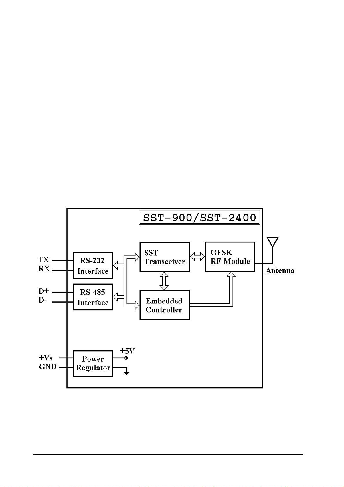
1. Introduction
The SST-900 and SST-2400 are radio modems that can be
used in multiple access networking. The transmission method in-
cludes peer-to-peer, multi-point structure for wireless data
communication. Based on direct sequence spread spectrum and
RF technology operating in ISM bands, 902-928Mhz for SST-900
and 2400-2483.5MHz for SST-2400.
1.1 Block Diagram

5
Wireless Radio Modem Users ManualRev:B1.2
1.2 Specifications
1.2.1 SST-900EXT Wireless Radio Modem
RF Communication Transceiver
Frequency Band : 909 to 924 MHz for SST-900
hannel Spacing : 2.048 MHz (8 channels jumper select)
Output Power : 20±2 dBm
Modulation : GMSK
Time Division Duplexing
Transimition Range : Max 300M
SST Transceiver
Direct Sequency Spread Spectrum
Non-Overlapping hannels : 8 channels, jumper select (only for
full-duplex operation)
Full-duplex or Half-duplex, jumper select
Synchronization or Asynchronization, jumper select
Serial Communication Interface
RS-232(TxD, RxD, GND) and RS-485(D+, D-), jumper select
Baudrate : 600bps to 57600bps, jumper select
Environment
Operating Temperature : 0° to 50°
Storage Temperature : -30° to 70°
Power Supply
Input : +10 to +30VD , unregulated
onsumption : 1.5W

6
Wireless Radio Modem Users Manual Rev:B1.2
1.2.2 SST-2400EXT Wireless Radio Modem
RF Communication Transceiver
Frequency Band : 2426 to 2458 MHz
hannel Spacing : 2.048 MHz (8 channels jumper select)
Output Power : 20±2 dBm
Modulation : GMSK
Time Division Duplexing
Transimition Range : Max 300M with bundled antenna
Max 1000M with SST-2400A-3 antenna
Max 5000M with SST-2400A-12 antenna
Max 5000M with SST-2400A-13 antenna
SST Transceiver
Direct Sequency Spread Spectrum
Non-Overlapping hannels : 8 channels, jumper select (only for
full-duplex operation)
Full-duplex or Half-duplex, jumper select
Synchronization or Asynchronization, jumper select
Serial Communication Interface
RS-232(TxD, RxD, GND) and RS-485(D+, D-), jumper select
Baudrate : 600bps to 57600bps, jumper select
Environment
Operating Temperature : 0° to 50°
Storage Temperature : -30° to 70°
Power Supply
Input : +10 to +30VD , unregulated
onsumption : 1.5W
7
Wireless Radio Modem Users ManualRev:B1.2
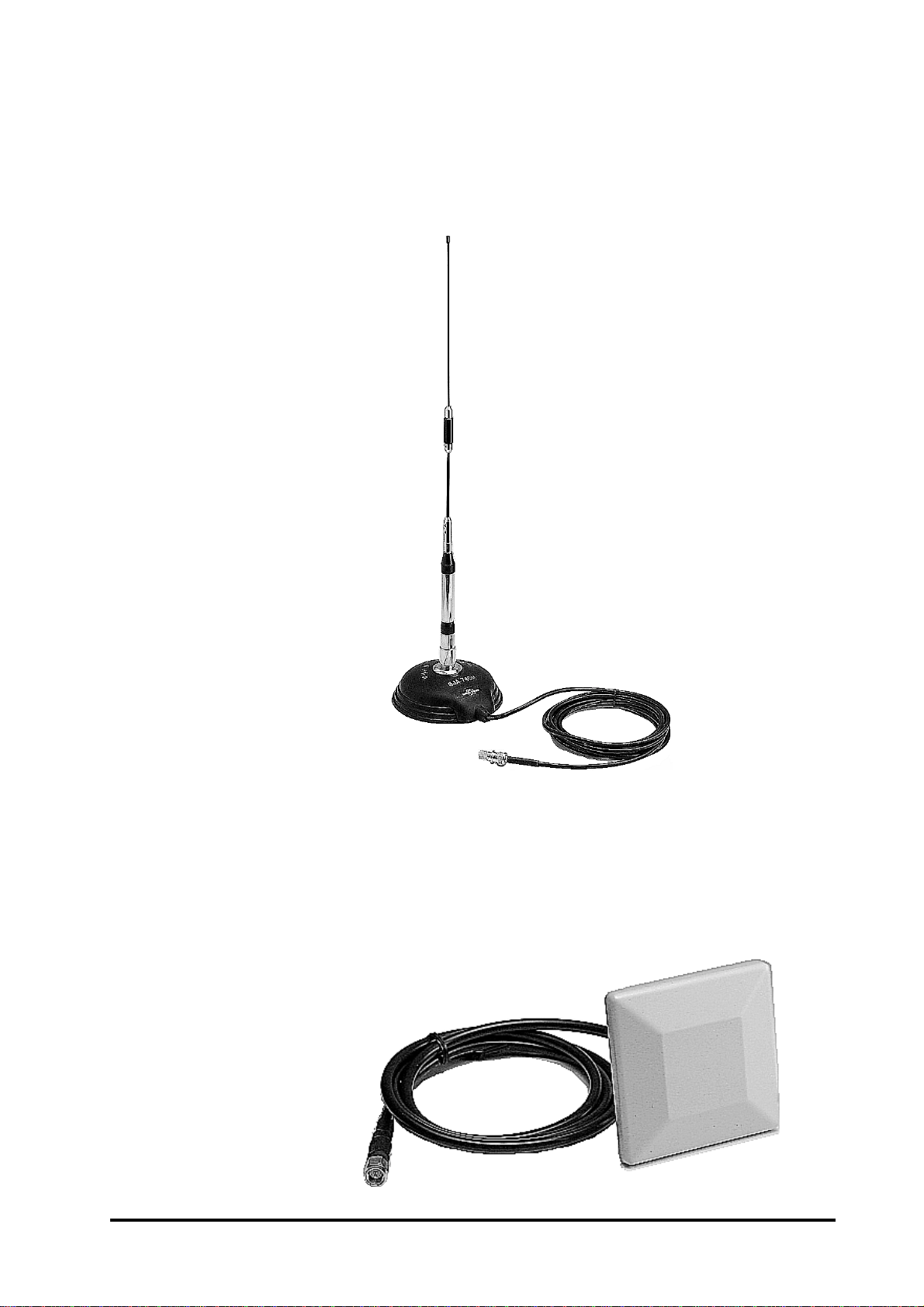
1.2.3 SST-900A External 900MHz Antenna
External antenna for SST-900EXT
Maximum Distance : 1000M
Weight : 1000g
Antenna Gain : 5dB
1.2.4 SST-2400A-3 External 2.4 Hz Antenna
External antenna for SST-2400
Maximum Distance : 1000M
Weight : 150g
Antenna Gain : 3dB

8
Wireless Radio Modem Users Manual Rev:B1.2
1.2.5 SST-2400A-12 External 2.4 Hz Antenna
External antenna for SST-2400
Maximum Distance : 5000M
Weight : 850g
Antenna Gain : 12dB
1.2.6 SST-2400A-13 External 2.4 Hz Antenna
External antenna for SST-2400
Maximum Distance : 5000M
Weight : ???g
Antenna Gain : ??dB

9
Wireless Radio Modem Users ManualRev:B1.2
1.3 Pin Assignment
DSR Reserved signal of diagnostic
RX Receive of RS-232
TX Transimit of RS-232
GND Ground of RS-232
(Y)D+ Data+ of RS-485
(G)D- Data- of RS-485
(R)+Vs +10 to +30V D power supply input
(B)GND Ground of power supply input

10
Wireless Radio Modem Users Manual Rev:B1.2
1.4 Jumper Setting
Factory default jumper setting :
(1) hannel 3 (2) Frequency 915.968/2439.936MHz
(3) Baudrate 9600bps (4) Full-duplex
(5) Slave (6) Synchronous
(7) Interface RS-232
This manual suits for next models
4
Table of contents
Other ICP DAS USA Radio Modem manuals


