Satel SATELLINE-3ASd Epic Pro 35W User manual

SATELLINE-3AS and SATELLINE-3ASd
1
IMPORTANT NOTICEIMPORTANT NOTICE
This manual is copyrighted by SATEL with all rights reserved. SATEL is an abbreviation for SATEL
OY. OY is an abbreviation for shareholders company according to Finnish law. No part of this
publication may be reproduced, transmitted, transcribed, stored on a retrieval system or
translated into any other language or computer language, in whole or part, in any form or by
means, whether it be electronic, mechanical, magnetic, optical, manual or otherwise without the
prior written consent of SATEL.
SATEL reserves the right to make changes to its products or to discontinue any product or service
without notice, and advises its customers to obtain the latest information available to verify that
the information relied on is current.
SATEL’s software is provided ‘as is’. All warranties and representations of any kind with regard to
the software are hereby disclaimed, including the implied warranties of merchantability and
fitness for a particular purpose. Under no circumstances will manufacturer or developer of the
software be liable for any consequential, incidental, special or exemplary damages even if
apprised of the likelihood of such damages occurring. Title to the software and all copyrights and
proprietary rights in the software shall remain with SATEL. You may not transfer, sub-license, rent,
lease, convey, copy, modify, translate, convert to another programming language, decompile or
disassemble the software for any purpose without SATEL’s prior written consent.
SATEL’S PRODUCTS ARE NOT DESIGNED, INTENDED, AUTHORIZED, OR WARRANTED TO
BE SUITABLE FOR USE ON LIFE-SUPPORT APPLICATIONS, DEVICES OR SYSTEMS OR OTHER
CRITICAL APPLICATIONS.
Salo, FINLAND 1999

SATELLINE-3AS and SATELLINE-3ASd
2
11 SATELLINE-3AS AND SATELLINE-3AsdSATELLINE-3AS AND SATELLINE-3Asd
IMPORTANT NOTICE .......................................................................................... 1
1SATELLINE-3AS AND SATELLINE-3ASD.......................................................... 2
2INTRODUCTION ............................................................................................ 5
3WARRANTY AND SAFETY INSTRUCTIONS ...................................................... 6
4SATELLINE-3AS AND SATELLINE-3ASD RADIO DATA MODEM ....................... 7
4.1 Technical Specifications........................................................................... 7
4.2 Basic Configuration and Installation....................................................... 8
4.2.1 Basic Configuration............................................................................................. 8
5DATA COMMUNICATION............................................................................... 9
5.1 RS-Interface............................................................................................. 9
5.1.1 D15 Connector................................................................................................... 9
5.1.1.1 Pin configuration ............................................................................................ 10
5.1.1.2 RS-232 Interface ............................................................................................ 11
5.1.1.3 RS-422 Interface ............................................................................................ 12
5.1.1.4 RS-485 Interface ............................................................................................ 12
5.1.1.5 Termination.................................................................................................... 12
5.1.1.6 RSSI indicator................................................................................................. 13
5.1.2 LED indicators................................................................................................... 14
5.1.3 RF Interface....................................................................................................... 15
5.1.4 Display and push buttons (SATELLINE-3ASd)....................................................... 16
5.2 Data Transmission (RS-interface) .......................................................... 17
5.2.1 Data format ...................................................................................................... 17
5.2.2 Handshaking..................................................................................................... 18
5.3 Data Transmission (Radio-interface)..................................................... 19
5.3.1 Addressing........................................................................................................ 19
5.3.1.1 Transmission .................................................................................................. 19
5.3.1.2 Reception....................................................................................................... 20
5.3.2 Error Correction ................................................................................................ 21
5.3.3 Repeater ........................................................................................................... 22
5.4 Timing and Delays During Data Transmission ...................................... 24
5.5 Tests ...................................................................................................... 24

SATELLINE-3AS and SATELLINE-3ASd
3
6SETTINGS.................................................................................................... 25
6.1 Changing the settings using terminal ................................................... 25
6.1.1 Frequency......................................................................................................... 26
6.1.2 Output power and sensibility .............................................................................. 27
6.1.3 Addressing........................................................................................................ 28
6.1.4 Serial port settings ............................................................................................. 29
6.1.5 Special functions ............................................................................................... 30
6.1.6 Tests................................................................................................................. 31
6.1.7 Restoring factory settings.................................................................................... 31
6.2 Changing the settings using the display ............................................... 32
6.2.1 Frequency......................................................................................................... 33
6.2.2 Addressing........................................................................................................ 34
6.2.3 Serial port settings ............................................................................................. 35
6.2.4 Special functions ............................................................................................... 36
6.2.5 Tests................................................................................................................. 36
6.2.6 Restoring factory settings.................................................................................... 37
6.2.7 Contrast............................................................................................................ 37
6.3 Changing the settings using SL-commands........................................... 38
6.3.1 Frequency......................................................................................................... 38
6.3.2 Addressing........................................................................................................ 39
6.3.3 Special functions ............................................................................................... 39
6.3.4 Forming of the SL Command ............................................................................. 40
7INSTALLATION............................................................................................ 42
7.1 The installation of a radio modem........................................................ 42
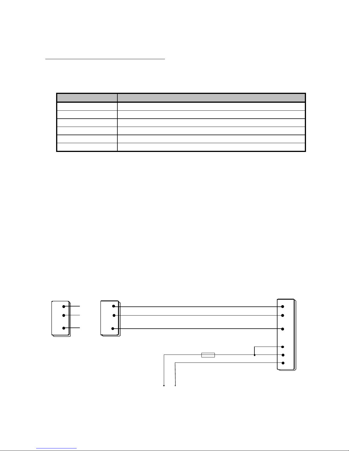
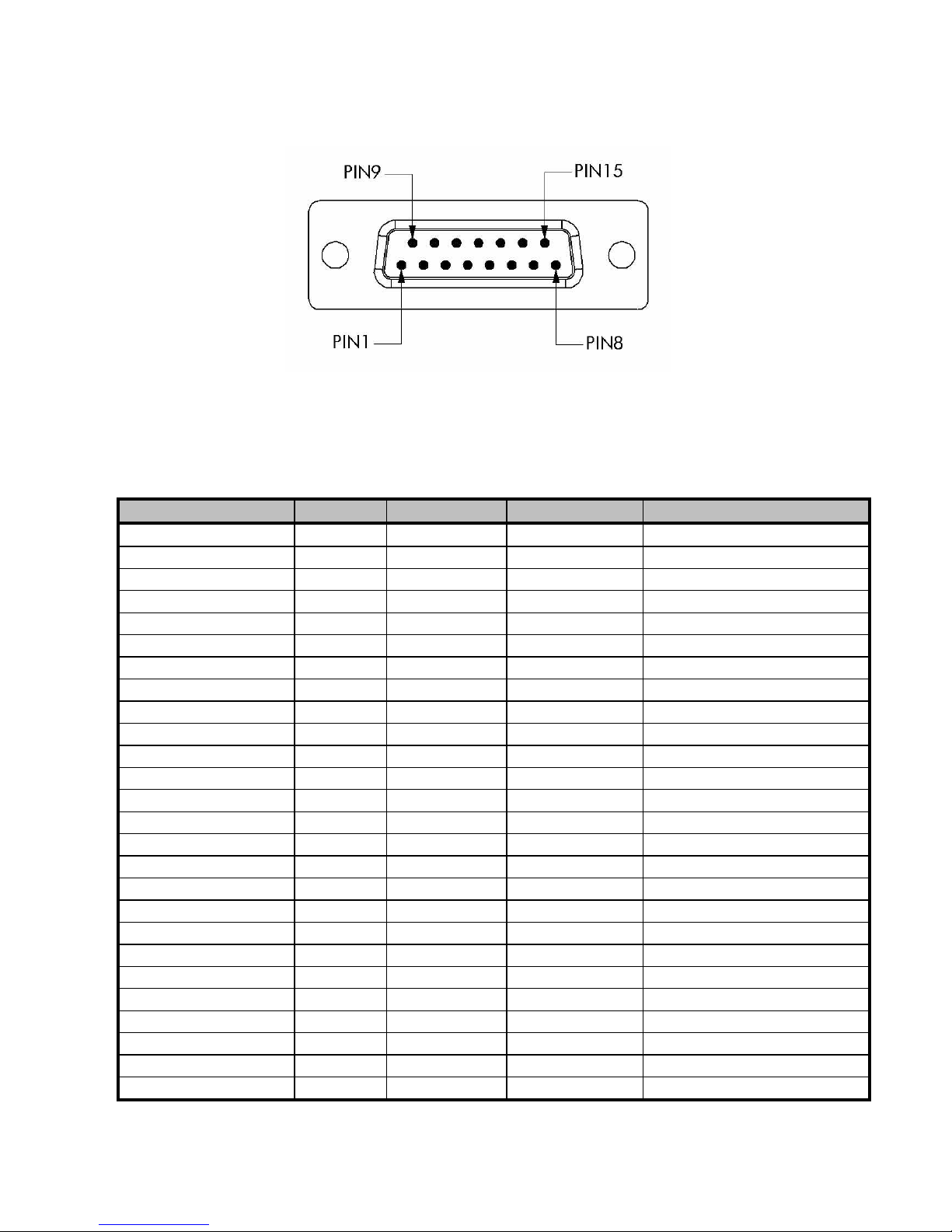
7.2 Interface Cable Connections.................................................................. 43
7.2.1 RS-232 Wiring .................................................................................................. 43
7.2.2 RS-422 Wiring .................................................................................................. 45
7.2.3 RS-485 Wiring .................................................................................................. 45
7.2.4 Power supply..................................................................................................... 45
7.3 Antenna Installation ............................................................................. 46
7.3.1 Hand portable equipment.................................................................................. 46
7.3.2 Equipment installed in vehicles ........................................................................... 46
7.3.3 Master station ................................................................................................... 46
7.3.4 General rules.................................................................................................... 47
8SYSTEM DESIGN .......................................................................................... 50
8.1 System Configurations........................................................................... 50
8.1.1 Factors affecting quality and distance of the radio connection.............................. 50
8.1.2 Radio field strength............................................................................................ 51
9CHECK LIST.................................................................................................. 52

SATELLINE-3AS and SATELLINE-3ASd
4
10 SOFTWARE UPDATE .................................................................................. 52
11 ACCESSORIES............................................................................................ 53
11.1 RS Cables............................................................................................... 53
11.2 RF Cables............................................................................................... 53
11.3 Antennas............................................................................................... 53
11.4 Power Supplies...................................................................................... 53
11.5 Filters .................................................................................................... 54
11.6 Battery Pack .......................................................................................... 54
11.7 Power Booster ....................................................................................... 54
12 APPENDIX A ............................................................................................. 55
13 APPENDIX B ............................................................................................. 56
13.1 Functional delays .................................................................................. 56
13.2 Transmission delays .............................................................................. 56
13.2.1 Transmission delays with 12.5 kHz radio channel................................................ 57
13.2.2 Transmission delays with 25 kHz radio channel................................................... 59

SATELLINE-3AS and SATELLINE-3ASd
5
22 INTRODUCTIONINTRODUCTION
SATEL is a Finnish electronics and telecommunications company that specialises in wireless data
communications. It designs, manufactures and markets radio modems for data communications and
alarm transfer systems. The main user groups include industrial companies, public organisations and
private persons.
SATEL is a leading supplier of radio modems in Europe. The Satel radio modems are type approved in
most European countries and elsewhere.
The amount of data transferred in a local area data communications network exhibits a tendency of
continuous growth. On the other hand, the average size of a communications system is increasing.
Satel’s response to these market tendencies is the SATELLINE-3AS, the first radio modem from SATEL with
a data speed of 19.2 kbps over the air. The data speed of RS interface is selectable between
300 … 38 400 bps.
The SATELLINE-3AS offers several new options related to the use of the radio modem. For the first time,
there is a built-in hardware compatibility with three selectable data interfaces, the RS-232, RS-422 and
RS-485.
A special model of the radio modem, the SATELLINE-3ASd, is equipped with a liquid crystal display
(LCD), which provides the user with several new, useful functions. The display can be utilised in the
SETUP mode for example during the implementation stage. Thanks to the display it is possible to change
the settings of the radio modem in the field without using an external terminal. It can also be used for
testing the quality of the radio connection between the stations.
The SATELLINE-3AS offers the possibility to use forward error correction (FEC) over noisy radio channels.
Error rate is minimised by means of advance checking and correction of the data packets. This is done
transparent to the user.
The radio modem has three basic operating modes: the Data Transfer mode, Setup mode and Test
mode. In the basic model SATELLINE-3AS the setting of operating parameters and selection of mode
and function is performed with a PC through the RS interface. The model SATELLINE-3ASd is equipped
with a LCD and four push buttons. In addition to changing the settings of the radio modem, the display
is used for testing the operating condition of the radio connection.
1. SATELLINE 3AS has a maximum data speed of 19.2 kbps and channel spacings 25 kHz or 12.5 kHz.
2. SATELLINE-3AS is compatible with the interface types RS-232, RS-422 and RS-485.
3. The model SATELLINE-3ASd is equipped with a LCD of its own, which facilitates setting up of the
radio modem.
4. The SATELLINE-3AS software includes a selectable error correction, which improves the functioning of
the radio modem under interference.
5. The software of the radio modem can be updated through the interface from a PC, without changing
the hardware.

SATELLINE-3AS and SATELLINE-3ASd
6
33 WARRANTY AND SAFETY INSTRUCTIONSWARRANTY AND SAFETY INSTRUCTIONS
Read these safety instructions carefully before using the product.
Warranty is void if the product is used against the instructions given in this manual or if the radio
modem is opened by unauthorised personnel.
The radio modem should only be used with the frequencies and power levels allowed by the
local authorities. SATEL is not responsible for any illegal use of its radio equipment.
The equipment described in this manual and technical description are only to be operated as
instructed in this manual. Correct and safe operation of this equipment can be assured only if
transportation, storage and operation are carried out correctly. This also applies to the
maintenance of this equipment.
To avoid electrostatic discharge (ESD) the radio modem and the terminal should be unpowered
while connecting data cables. Make sure that the different signal grounds in the devices have the
same potential. The power supply voltage must be checked to ensure the correct supply voltage
range is selected.

SATELLINE-3AS and SATELLINE-3ASd
7
44 SATELLINE-3AS and SATELLINE-3ASd RADIO DATA MODEMSATELLINE-3AS and SATELLINE-3ASd RADIO DATA MODEM
4.14.1 Technical SpecificationsTechnical Specifications
The equipment complies with the ETS 300 683 specification for EMC regulations, ETS 300 220
specification for channel spacing at 25 kHz channels, ETS 300 279 specification for EMC
regulations and ETS 300 113 specification for channel spacing at 12,5 kHz channels.
RADIO TRANSCEIVER
Frequency Range
Channel Spacing
Number of Channels
Frequency Stability
Type of Emission
Communication Mode
370...470 MHz
12,5 kHz/25 kHz
160/80
< ± 1.5 kHz
F1D
Half-Duplex
RADIO TRANSMITTER PART
Carrier Power
Carrier Power Stability
Adjacent Channel Power
Spurious Radiations
10 mW...1 W / 50 ohm
+ 2 dB / - 3 dB
according to ETS 300 220/ETS 300 113
RADIO RECEIVER PART
Sensitivity
Co-channel Rejection
Adjacent Channel Selectivity
Intermodulation Attenuation
Spurious Radiations
- 116... -110 dBm (BER < 10 E-3)
> - 12 dB
> 60 dB
> 65 dB
< 2 nW
DATA TRANSMISSION
Interface
Interface Connector
Data speed of RS Interface
Data speed of Radio Interface
Data Formats
RS-232 or RS-485, RS-422
D15, female
300 - 38400 bps
19200 bps (25 kHz channel)
9600 bps (12,5 kHz channel)
Asynchronous RS-232, RS-422, RS-485
GENERAL
Operating Voltage
Power Consumption
Temperature Range
Antenna Connector
Construction
Size H x W x D
Installation Plate
Weight
+ 9 ...+ 30 VDC
2.5 VA typical (Receive)
6.6 VA typical (Transmit)
0.05 VA typical (STAND-BY mode)
-25 °C...+55 °C
TNC, 50 ohm, female
Aluminium enclosure
137 x 67 x 29 mm
130 x 63 x 1 mm
250 g

SATELLINE-3AS and SATELLINE-3ASd
8
4.24.2 Basic Configuration and InstallationBasic Configuration and Installation
4.2.1 Basic Configuration
The radio modem is supplied with the following settings (if not otherwise ordered):
Radio frequency Selection of the Customer
Radio settings 500 mW / -110 dBm (25 kHz) or -112 dBm (12,5 kHz)
Addressing RX Address OFF / TX Address OFF
Serial port 1 ON / 19200 / 8 bit data / None / 1 stop bit [ RS-232 ]
Serial port 2 OFF / 19200 / 8 bit data / None / 1 stop bit [ RS-232 ]
Additional setup Error Correction OFF / Repeater Function OFF / SL-commands OFF
Tests Test Mode Inactive
Connect the power cables (+Vband GND) to a 9 – 30 VDC power supply with a power rating of
at least 1 A. Also connect the DTR -pin to a positive voltage. If the DTR pin is not connected, the
radio modem is in the STAND-BY mode and will not transmit or receive data.
As a terminal program you can use SaTerm which is available free from your local dealer. You
can also use HyperTerminal in most of the Windows operating systems or any other terminal
program. Basic settings for any terminal program are computer serial port COM1, 19200 bps, 8
bit data, none parity, 1 stop bit . If the serial port COM1 of the computer is occupied you should
use another serial port.
NOTE!
When you want to program the radio modem in the SETUP mode via the terminal, the terminal
speed should be set to 9600 bps.
Basic configuration for port COM1 RS-232
FUSE 630 mA slow
DTR
+Vb
GND
11
9
7
1
15
8
+Vb GND
RADIO MODEM
TD
RD
2
3
7
25-PIN D-CONNECTOR
SGND
TD
RD
2
3
5
9-PIN D-CONNECTOR
SGND
TD
RD
SGND

SATELLINE-3AS and SATELLINE-3ASd
9
55 DATA COMMUNICATIONDATA COMMUNICATION
5.15.1 RS-InterfaceRS-Interface
5.1.1 D15 Connector
The radio modem is referred as a DCE (Data Communication Equipment) and PC’s and
terminals as DTE’s (Data Terminal Equipment). The SATELLINE-3AS radio modem has a 15-pin
‘D’ type female connector for all the interface connections.
The design of the radio modem will take into account any filtering necessary on these
connections to ensure compliance with spurious emissions and EMC regulations. The user should
therefore not need to take any further precautions against emissions out of the radio modem.
The radio modem has two RS-ports, COM1 and COM2. Port COM1 has RS-232-level interface
and port COM2 has RS-232, RS-422 and RS-485 interfaces. Only one port can be used for
communication at a time. Port COM2 can be used in RS-422 or RS-485 mode only if it is
physically set at the factory, the mode change is not possible afterwards by software only.
NOTE!
WHEN MODE PIN (12) IS CONNECTED TO THE GROUND (SETUP MODE) THE RADIO
MODEM ALWAYS USES PORT COM1 (PINS 7,9,11) ! So if you are using port COM2
for communication you have to use an appropriate cable for SETUP mode.

SATELLINE-3AS and SATELLINE-3ASd
10
5.1.1.1 Pin configuration
D-15 female connector in the radio modem
Pin number is the number of the pin in the radio modem.
Direction IN is data from DTE (Data Terminal Equipment) to the radio modem.
Direction OUT is data from the radio modem to the DTE.
PORT AND LEVEL PIN DIRECTION DATA PIN NAME
COM1 RS-232 2OUT CD Optional *
5OUT RSSI Optional *
6OUT CTS Optional *
7-SGND Signal Ground
9OUT RD Receive Data
10 OUT DSR Optional *
11 IN TD Transmit Data
13 IN RTS Optional *
COM2 RS-232 2OUT CD Optional *
3OUT RD Receive Data
4IN TD Transmit Data
5OUT RSSI Optional *
7-SGND Signal Ground
COM2 RS-422/485 2OUT A’ Receive data positive
3OUT B’ Receive data negative
4IN ATransmit data positive
5IN BTransmit data negative
COMMON PINS
1-DTR ON (Vb) / STAND-BY (NC)
8-GND Power ground
12 -MODE DATA (NC) / SETUP (GND)
15 -VbOperating voltage
14 -VbOperating voltage optional *
*) Optional pins are not necessary for the normal operation, they should be used if needed.

SATELLINE-3AS and SATELLINE-3ASd
11
RSSI = Received Signal Strength Indicator, can be used for monitoring the signal quality with a
DTE.
CTS = Clear To Send, used in handshaking. Indicates when the radio modem is ready to accept
data on the TD line.
SGND = Signal GrouND. Can be connected to GND.
RD = Receive Data. Data from the radio modem to the DTE.
DSR = Data Set Ready. Indicates "ON" state of the modem. The signal level is the same as the
DTR signal level.
TD = Transmit Data. Data from the DTE to the radio modem.
RTS = Request To Send, used in handshake. The DTE usually enables RTS when it is ready to
receive data. NOT IMPLEMENTED in the radio modem.
CD = Carrier Detect. Indicates a strong signal on the radio channel, can be used to avoid data
collisions on the radio channel.
DTR = Data Terminal Ready, when connected to the operating voltage (Vb) the radio modem is
ON, when not connected (NC) the radio modem is in the STAND-BY mode
MODE = selects the DATA mode if not connected, and SETUP mode if grounded. SETUP mode
is only needed when installing the radio modem, usually the radio modem is always in the DATA
mode.
Vb= Operating voltage.
5.1.1.2 RS-232 Interface
RS-232 standardises serial communication between computers and between computer terminals
and modems. Most applications use the RS-232 standard for interfacing peripherals to personal
computers. RS-232 uses transmission lines in which the state of each signal is represented by
referencing the voltage level of a single line to ground. RS-232 was designed for serial
communication cable up to distances of 15 m. RS-232 is implemented differently in different
peripherals so all peripherals using RS-232 are not necessarily compatible. (See also paragraph
7.2.1 for wiring).

SATELLINE-3AS and SATELLINE-3ASd
12
5.1.1.3 RS-422 Interface
RS-422 defines a serial interface much like RS-232. However, RS-422 uses balanced (or
differential) transmission lines. Balanced transmission lines use two transmission lines for each
signal. The state of each signal is represented by the relative voltage of the two lines to each
other. For example, the TX signal is carried on two wires, wire A and wire B. A logical 1 is
represented by the voltage on line A being greater than the voltage on line B. A logical 0 is
represented by the voltage on line A being less than the voltage on line B. Differential voltage
transmission creates a signal which is more immune to noise as well as voltage loss due to
transmission line effects. Thus, you can use RS-422 for greater cable distances (up to 1 km) than
RS-232. (See also paragraph 7.2.2for wiring)
5.1.1.4 RS-485 Interface
RS-485 expands on the RS-422 standard by increasing the number of devices you can use from
10 to 32 and by working with Half-duplex bus architectures. Only one pair of cablesis needed
compared to the two pairs needed in RS-422. Unlike the RS-422 standard, RS-485 addresses
the issue of using multiple transmitters on the same line. RS-485 defines the electrical
characteristics necessary to ensure adequate signal voltages under maximum load, short-circuit
protection, and the ability to withstand multiple drivers driving conflicting signals at the same
time. (See also paragraph 7.2.3 for wiring)
5.1.1.5 Termination
Each differential pair of wires is a transmission line.You must properly terminate the line to
prevent reflections. A common method of terminating a two-wire multidrop RS-485 network is to
install terminating resistors at each end of the multidrop network. If you daisy chain multiple
instruments together, you need a terminating resistor only at the first and last instruments. The
terminating resistor should match the characteristic impedance of the transmission line (typically
100~120 ohm).

SATELLINE-3AS and SATELLINE-3ASd
13
5.1.1.6 RSSI indicator
Received Signal Strength Indicator, RSSI, ( pin 5) announces the received field strength of the
signal. This signal can be used for the approximate determination of the signal level. In the
following figure is the typical voltage level as a function of the signal level. Notice that voltage
drops with a good signal level (>-25dB). This occurs when the distance of the two modems is
less than 10 meters.
0
0,5
1
1,5
2
2,5
3
3,5
4
4,5
OFF -120 -118 -116 -110 -100 -90 -80 -70 -60 -50 -40 -30 -25 -20 -15 -10
RSSI-pin level / V
Signal strength / dBm

SATELLINE-3AS and SATELLINE-3ASd
14
5.1.2 LED indicators
The five LED’s at the front of the radio modem indicate the operation of RS-interface:
LED symbol Indication Red Green
RTS Status of RTS-line on port
COM1
Active Inactive
CTS Status of CTS-line on port
COM1
Active Inactive
TD Data on TD-line Data on line No data
RD Data on RD-line Data on line No data
CD Status of radio signal carrier
level
Active Inactive
RTS indicates the state of the pin 13. The data terminal equipment (DTE) usually enables RTS
when it is ready to receive data. By default the DTE enables RTS to active.
CTS indicates the state of the pin 6. It is active when the radio modem is ready to receive data
for radio transmission.
TD indicates the radio modem is receiving data on the RS line.
RD indicates the radio modem is sending data on the RS line.
CD indicates a radio signal exceeding the sensibility level.
NOTE!
If you are using the hardware (RTS/CTS) handshake, the RTS is NOT IMPLEMENTED in the
radio modem.

SATELLINE-3AS and SATELLINE-3ASd
15
5.1.3 RF Interface
The antenna connectors type is TNC and the impedance is 50 ohms. The transmitter output
power is between 10mW - 1W.
The bitrate in the radio channel depends on the radio channel width, with a 25 kHz channel the
bitrate is 19200 bps and 9600 bps with 12,5 kHz radio channel. The radio bitrate is always the
same independent of the RS line bitrate. If the RS line bitrate is slower or faster than the radio
channel bitrate the radio modem buffers the data temporarily so it will not be lost.
OUTPUT POWER mW OUTPUT POWER dBm
10 10
20 13
50 17
100 20
200 23
500 27
1000 30
Conversion table for output power
NOTE!
Setting the radio data modem to a power level other than those specified by the local
authorities is strictly forbidden. The use of non-approved power level can lead to prosecution
by the local authorities. SATEL is not responsible for any illegal use of its radio equipment.

SATELLINE-3AS and SATELLINE-3ASd
16
5.1.4 Display and push buttons (SATELLINE-3ASd)
The SATELLINE-3ASd radio modem contains a back-lit liquid crystal display (LCD). The display
shows the settings of the radio modem, field strength and battery charge condition. Using the
LCD and the push buttons it is possible to change the settings of the radio modem without using
an external terminal.
The display units back light is activated by pushing any of the buttons.
Display in the DATA
MODE
öÄÄÄÖÖ äÄÄÄÖÖ
468.2000 MHz
COM1:19200N81
Setup
Display showing the
SW Version
SATELLINE-3AS
Version 1.23
Display in the SETUP
MODE
RF frequency
>Addressing
Port 1
CANCEL ýþSetup
Select button
Cancel/Back button
Up button Down button
Current frequency
Current port setting
Functions of the Push
Buttons
Active line cursor
Field strength Operating
of the last voltage
received message level

SATELLINE-3AS and SATELLINE-3ASd
17
5.25.2 Data Transmission (RS-interface)Data Transmission (RS-interface)
5.2.1 Data format
The SATELLINE-3AS radio modem uses asynchronous data format. Asynchronous transmission
does not require a continuous synchronising signal from the transmitter to the receiver. The data
bits of each character are preceded by a start bit and followed by one or two stop bits. They are
inserted after the data bits to provide a minimum period between characters.
Standard data bit rates for SATELLINE-3AS are 300, 600, 1200, 2400, 4800, 9600, 19200
and 38400 bps (bits per second).
The length of the data field should be 7, 8 or 9 bits. If the data length is 9 bits, the selection of
parity has to be NONE.
When a parity bit is used, its logic state depends on the specific character code and whether the
agreed protocol specifies even parity or odd parity. The parity bit is simply made 1 or 0, as
required, to make the total number of 1s in the data an even (even parity) or an odd (odd parity).
Note that the parity bit itself is included in the count, but the stop bit or stop bits are excluded.
The whole character length includes start bit, data bits, parity bit and stop bit or bits. The
character length is 10, 11 or 12 bits.
Start Data Parity Stop
Asynchronous data format
Example: 8 bit data value is 204 ( 11001100 binary ), start bit is 0, parity is none, 0 or 1and
stop bit 1.
The possible characters are:
DATA FORMAT CHARACTER CHARACTER LENGTH
8 bit, no parity, 1 stop bit 0110011001 10 bit
8 bit, even parity, 1 stop bit 01100110001 11 bit
8 bit, odd parity, 1 stop bit 01100110011 11 bit
8 bit, no parity, 2 stop bits 01100110011 11 bit
8 bit, even parity, 2 stop bits 011001100011 12 bit
8 bit, odd parity, 2 stop bits 011001100111 12 bit
It can be seen that there are always 2, 3 or 4 extra bits per one data word, that must be taken
into account when calculating the system throughput.
If the data speed, character length, parity or the number of stop bits are incorrectly set, errors will
appear in transmission. At reception they appear as "error characters" or as an incorrect
operation of the modem.

SATELLINE-3AS and SATELLINE-3ASd
18
The data settings of each station of the system can be different except for the data length. The
data length must always be same in the whole system.
The data format can be selected in the SETUP mode.
5.2.2 Handshaking
Handshaking must be used if there is a need to control the transmission between a terminal and
a radio modem. For example, SATELLINE-3AS may not be ready to send because the radio
channel is busy or the data buffer is full. Handshaking is used to prevent data loss.
Handshaking is not needed under the following conditions:
•radio channel is relatively free, it can be seen from the CD led
•your system can handle overlapping messages
The 3AS supports partly hardware handshaking (RTS/CTS). Hardware handshaking (or flow
control) works by altering the state of the RTS (Request To Send) and CTS (Clear To Send) lines
on the RS232-interface between the radio modem and the data terminal equipment (DTE). CTS
is used by the radio modem on the sending end of a transmission. When the radio modem is
ready to receive data, it changes the state of the CTS signal to active and the DTE starts
transferring data. If the radio modem is unable to accept the data as fast as it is received from
the DTE, the radio modem will change the state of the CTS to inactive to inform the DTE that the
modem buffer is almost full. The DTE will then suspend data transfer. Once the radio modem
has emptied its buffer by transmitting the data to the radio channel, it will change the state of the
CTS back to active again. The CTS is always on in the radio modem.
RTS is changed by the DTE when receiving data. When the DTE cannot accept data at the rate at
which it is sent on the RS232-interface, it will disable RTS. The DTE enables RTS again when it is
ready to resume receiving data from the radio modem. THE RTS IS NOT IMPLEMENTED IN THE
RADIO MODEM. IT WILL IGNORE THE RTS SIGNAL. Usually this is not a problem since most of
the DTE’s are fast enough to receive data from the radio modem.

SATELLINE-3AS and SATELLINE-3ASd
19
5.35.3 Data Transmission (Radio-interface)Data Transmission (Radio-interface)
5.3.1 Addressing
It is possible to use addresses both in data transmission and reception on the radio channel. The
address consists of two data characters (totalling 16 bits). The address consists of the first two
characters of the data packet, that the radio modem adds to every sent packet and/or checks for
in every received packet. (compare to SL-command SLAxy, where ADD H corresponds to x and
ADD L corresponds to y)
Address range is from 0000h (h for hexadecimal) to FFFFh in hexadecimal format (0-65535 in
decimal format). The maximum data length is 1 kB (kiloByte) with a repeater, in normal use it is
not constrained.
ADD H ADD L DATA
For example, address 1234h (4660 decimal) where 12 is ADD H and 34 is ADD L.
For another example, ABFFh (44031 decimal) where AB is ADD H and FF is ADD L.
The addresses can either be the same in both directions or the transmitting and the receiving
addresses can be different. It is also possible to transfer the received address to the RS interface.
You can use addressing for
-preventing unwanted messages for DTE’s that might not handle it (multi-slave system)
-preventing messages circulating between repeaters
5.3.1.1 Transmission
Data Address Data
DataData
Fig 1. Address of transmission has been
set OFF. Radio modem will transmit the
data packet as such.
Fig 2. Address of transmission has been
set ON. Radio modem will add the
address to the beginning of the data
packet.

SATELLINE-3AS and SATELLINE-3ASd
20
5.3.1.2 Reception
Address Data
Data
Address Data
Fig 3. Address of reception has been set
ON, and address of radio modem is
identical to address of received data
message.
Radio modem will remove the address
from the beginning of data packet and will
send data to the data line.
Fig 4. Address of reception has been set
ON, but the address of radio modem is
different from the address of the received
data message. Radio modem will prevent
data packet from being transferred to the
data line.
Data
Data
Data
Address Data
Address Data
ERROR
Fig 5. Address of
reception has been set
OFF.
Radio modem will
transfer all received data
to data line.
Fig 6. Address of reception
has been set OFF.
Radio modem will consider
characters of the address
to be a part of data and
will send all characters to
data line.
Fig 7. Address of reception
has been set ON but there
is no address in the data
packet.
Radio modem will transfer
data to data line ONLY if
the address is valid.
Other manuals for SATELLINE-3ASd Epic Pro 35W
2
This manual suits for next models
1
Table of contents
Other Satel Radio Modem manuals

Satel
Satel M2M User manual

Satel
Satel SATEL-EASy+ YM6015 User manual

Satel
Satel Proof-TR489 User manual

Satel
Satel Proof-TR4 User manual

Satel
Satel SATELLAR XT 5R User manual

Satel
Satel SATELLINE-3ASd Epic Pro 35W User manual

Satel
Satel SATELLINE-3ASd Epic Pro 35W User manual

Satel
Satel Compact-4BT User manual

Satel
Satel SATELLINE-EASy Pro 35W User manual

Satel
Satel SATEL-EASY PRO+ User manual