ICP DAS USA I-7530A-MR-FD User manual

P1
I-7530A-MR-FD Quick Start
v1.0, October 2020
Packing List
In addition to this guide, the package includes the following items:
1.
I-7530A-MR-FD
RS-232 cable
(CA-0910)
Screw Driver
Quick Start
Technical Support
service@icpdas.com
www.icpdas.com
Resources
How to search for drivers, manuals and
spec information on ICP DAS website.
For Mobile Web
For Desktop Web
I-7530A-MR-FD
I-7530A-MR-FD

P2
1.Introduction
This manual introduces the user to the methods used to implement
the I-7530A-MR-FD module into their applications in a quick and easy
way. This only provides with the basic instructions. For more detailed
information, please refer to the I-7530A-MR-FD user manual located on
the ICP DAS CD-ROM or download it from the ICP DAS web site:
( https://www.icpdas.com/en/product/I-7530A-MR-FD )
The goal of this manual is focused on helping users to quickly
familiarize themselves with the I-7530A-MR-FD module and the data
exchanged between RS-232/485/422 and CAN communication
interfaces. Here, we use two I-7530A-MR-FD modules (called the
I-7530A-MR-FD_A and the I-7530A-MR-FD_B) as the example to
demonstrate how to use the I7530A-MR-FD modules. The architecture
of this example is depicted below.
When the I-7530A-MR-FD receives a valid Modbus RTU command,
it converts this command into a CAN message and transmits it into the
CAN network. Based on the same reasoning, when a CAN message is
received via the I-7530A-MR-FD, the message will be stored in the
I-7530A-MR-FD until being obtained by the Modbus RTU master.
2.Hardware Installation
Users need to make a hardware connection between the two
I7530A-MR-FD modules before the application. The details of this are
illustrated below:
Step1: Set-up the 120Ωterminator
resistor of the module A and B.

P3
Before you continue, if you have changed the settings from default then
it is necessary to open the cover for each I-7530A-MR-FD and
re-configure their JP3 jumpers to enable them again, as shown in below
figure. However if the I-7530A-MR-FD’s still have their default settings
then it is not necessary to open and reset them because the default
configuration is enabled.
Enable (default),
(Activate)
Step2: Power connection for the I-7530A-MR-FD_A and B.
Connect the +Vs and GND pins of the I-7530A-MR-FD module to
the DC power supply (10~30VDC).
Step3: RS-232 connection
Connect the RS-232 ports of the I-7530A-MR-FD_A and
I-7530AMR-FD_B to the RS-232 COM1 and COM2 of the PC by
using the attached cable CA-0910 respectively. You can use the
attached cable CA-0910 to do that.
Step4: CAN bus connection
Connect the CAN ports of these two I-7530A-MR-FD modules
using the following architecture. If necessary, you may refer the
cable CA-0910-C for wiring conveniently. Please refer to the
following picture.

P4
http://www.icpdas.com/products/Accessories/cable/cable_selectio
n .htm
3.I-7530A-MR-FD Parameter Configuration
Before starting the I-7530A-MR-FD converter tests, users need to
configure the RS-232/485/422, Modbus and CAN parameters via the
UART2CAN Utility tool. The details of this procedure are shown below.
Step1: Turn off the DC power connected with these two
I-7530A-MR –FD modules.
Step2: Set the Init/Normal switches on the back of the
I-7530A-MR-FD_A to the “Normal” position. Then, turn on the DC power.
Afterwards, set the Init/Normal switches to the “Init” position and hold it
at least 3 seconds. The CAN LED and UART LED of the
I-7530A-MR-FD_A will flash approximately once per second. That
means that the I7530A-MR-FD is working in the configuration mode.
Step3: Run the UART2CAN Utility. The “UART2CAN Utility.exe” is
located on the product CD-ROM or is downloaded from the web site:
https://www.icpdas.com/en/product/I-7530A-MR-FD
Download Center-> Utility &Tool->Utility
Step4: Select the proper PC COM port No., baud rate and data format,
which are used to be communicated with the I-7530A-MR-FD_A. When
the Utility starts, the following dialog will be popped up. The default
setting of the PC COM port field is configured at 115200bps, 8 Data Bits,
1 Stop bit, and no parity.

P5
Step5: Click the “Connect” button. If the connection is successful, the
UART2CAN Utility will show the communication information of the
I-7530A-MR-FD_A module, as shown in the following figure.
Step6: Set the communication mode of the I-7530A-MR-FD_A. Here,
use Modbus Slave mode for example.
Step7: In order to match the RS-232 parameters of the PC COM port,

P6
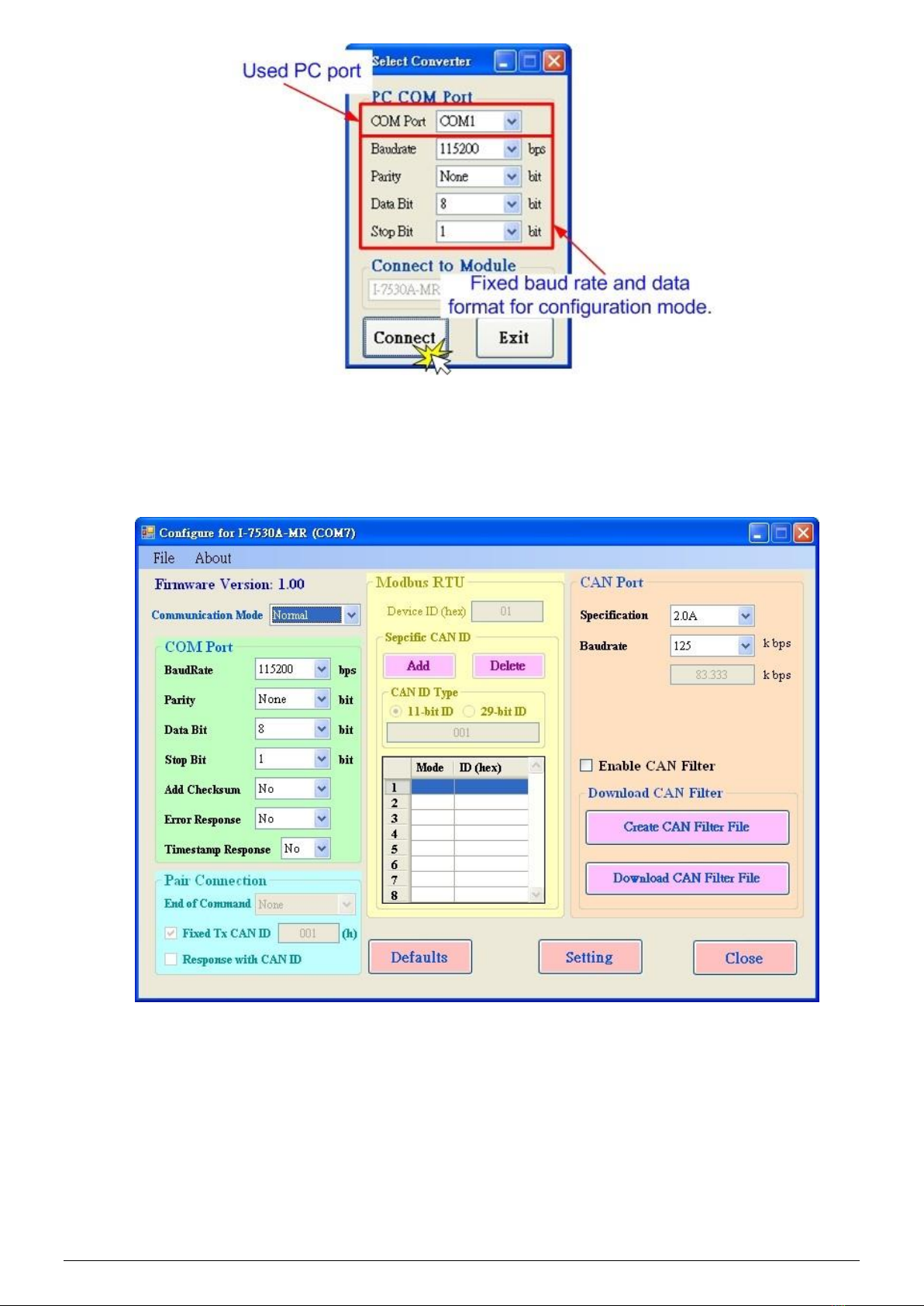
please configure the COM parameters of the I-7530A-MR-FD_A as
follows:
Baud rate : 115200bps
Data bits : 8
Stop bits : 1
Parity : None
Checksum : No
Step8: Set the CAN baud rate of the I-7530A-MR-FD_A. Here, use
125 kbps for CAN baud, and uncheck the “Enable CAN Filter”
item (For more information about CAN Filter configuration,
please refer to the section 3.4 of the user manual).
Step9: Set the Device ID of the I-7530A-MR_A and I-7530A-MR-FD_B
as 1 and 2 respectively. Here the “Specific CAN ID” field does not
be used (For more information about Modbus Slave configuration,
please refer to the section 5 of the user manual)
Step10: Click the “Setting” button to save these CAN/COM parameters
into the EEPROM of the I-7530A-MR-FD_A.
Step11: Repeat Step 1 ~ Step 10 to configure the I-7530A-MR-FD_B
converter with the same configurations as the I-7530A-MR-FD_A.
4.Testing the I-7530A-MR-FDs
Step1: Turn off the DC power connected with these two I-7530A-MR-FD
modules.
Step2: Set the Init/Normal switches on the back of the
I-7530A-MR-FD_A and I-7530A-MR-FD_B to the “Normal” position.
Then, turn on the DC power. The CAN LED and UART LED of the
I-7530A-MR-FD_A and B will be turned off. It means these two
I-7530A-MR-FD converters are working in the operation mode.
Step3: Run the UART2CAN Utility twice. Then duplicate
I-7530A-MR-FD Utility dialogs will be displayed on the PC’s screen.
Assume that one is named as Utility_A and the other is Utility_B.
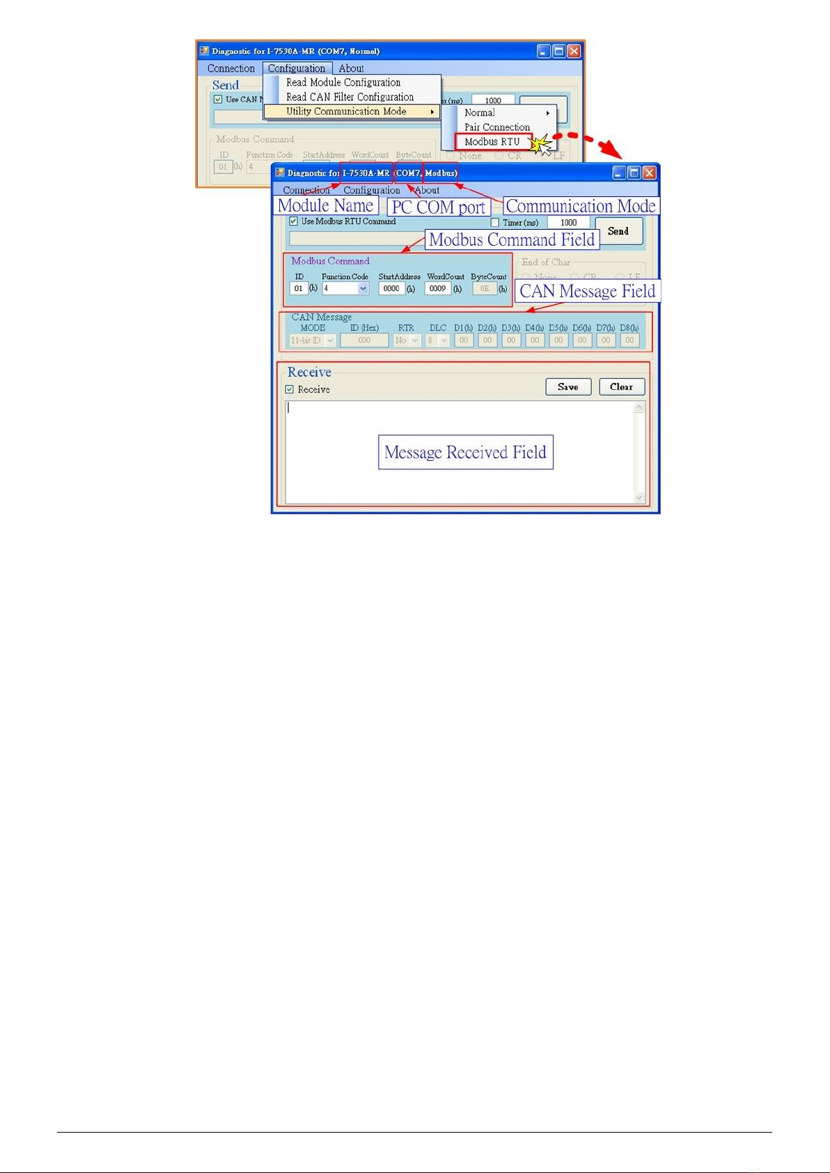
Step4: Select the proper COM port parameters and configure the
RS-232 COM1 and the RS-232 COM2 of the PC. The COM1 and COM2
ports of the PC will be used for connecting with the I-7530A-MR-FD_A
and I-7530A-MR-FD_B respectively. Then change the communication
mode of Utility_A and Utility_B to Modbus Slave mode. The two Utility
dialogs are similar with the following picture.

P7
Step5: Check the “Use CAN Message” checkbox and key-in the correct
data in the “Modbus Command” and “CAN Message” fields of the
Utility_A. Click the “Send” button. Then, the Utility_A will automatically
transfer this CAN message to the Modbus RTU command and send it
out through the PC RS-232 COM1 port. After the I-7530A-MR-FD_A
receives this command, it will convert the Modbus RTU message to the
CAN message, and send it to the CAN network. While the
I-7530A-MR-FD_B receives the CAN message transmitted from
I-7530A-MR-FD_A. The message will be converted and stored in the
I-7530A-MR-FD_B until being obtained by the Modbus RTU master.
Then, use the Modbus RTU command (function code 04hex) to get the
CAN message by the Utility_B.
Detailed steps of this are shown in the following figure.

P8
○
9
○
8
○
7
○
6
Utility B
Utility A
○
5
④
③
②
①
Other manuals for I-7530A-MR-FD
2
Table of contents