ICP DAS USA ZB-2510 User manual

ZB-2510 Series User Manual, Ver. 1.2 Page 1
ZB-2510 Series User Manual
Warranty
All products manufactured by IC DAS are warranted against defective
materials for a period of one year from the date of delivery to the original
purchaser.
Warning
IC DAS assumes no liability for damages consequent to the use of this
product. IC DAS reserves the right to change this manual at any time
without notice. The information furnished by IC DAS is believed to be
accurate and reliable. However, no responsibility is assumed by IC DAS
for its use, or for any infringements of patents or other rights of third
parties resulting from its use.
Copyright
Copyright 2009 by IC DAS. All rights are reserved.
Trademark
The names used for identification only may be registered trademarks of
their respective companies.

ZB-2510 Series User Manual, Ver. 1.2 Page 2
Table of Contents
1. Introduction......................................................................................................................... 3
2. Specifications...................................................................................................................... 4
3. roduct Description ......................................................................................................... 5
3.1 Internal I/O Structure............................................................................................. 5
3.2 Appearance................................................................................................................... 6
3.3 Dimensions (Units: mm) ............................................................................................. 7
4. Operating Modes and Applications .......................................................................... 8
4.1 Introduction................................................................................................................. 8
4.2 ZigBee Repeater usage.............................................................................................. 9
1. Broadcast Mode: ................................................................................................. 9
2. User-defined Route Mode: ............................................................................... 9
3. User-defined Route Mode with a back-up route:.......................................10
4.3 Applications.................................................................................................................12
5. Quick Start for the ZB-2510 Series..................................................................14
5.1 Installing the ZB-2000 Driver..................................................................14
5.2 Installing the Hardware and Driver ........................................................16
5.3 Installing the Configuration Tool............................................................ 20
5.4 Quick Configuration for the ZB-2510 Series ......................................22
6. Appendix ..............................................................................................................................24
7. Ordering Information................................................................................................... 27
8. Accessories ........................................................................................................................28

ZB-2510 Series User Manual, Ver. 1.2 Page 3
1. Introduction
What are the benefits of using ZigBee?
ZigBee is a specification based on the IEEE 802.15.4 standard for
wireless personal area networks (W ANs). It is targeted at applications
that require secure networking as well as high flexibility for network
expansion anytime new nodes are to be added. It is also widely used in the
industrial control field, in hospitals, labs and in building automation. Three
topologies are defined in the IEEE 802.15.4 standard: Star, Cluster Tree
and Mesh.
ZB-2510 Series
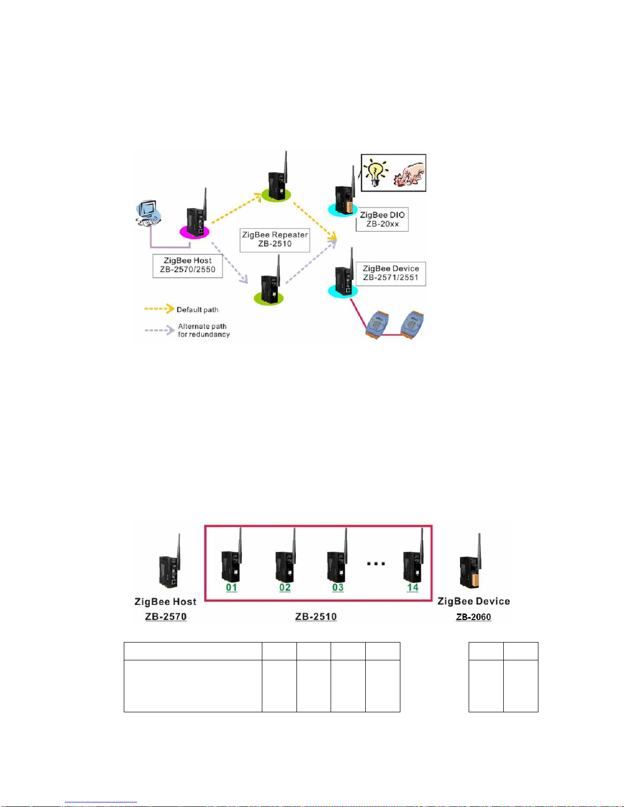
The ZB-2510 series are two ZigBee-based repeater modules included
in the IC DAS product line. The main difference between T and
A-version is the transmission range. The ZB-2510-T supports an
extended transmission range of up to 100 meters, whereas the
ZB-2510- A can transmit to a maximum of 700 meters. Both modules are
able to operate in broadcast and user-defined route modes. When the
repeater is set to broadcast mode, the transmission route is constructed
by the ZigBee Host. The repeater will forward any data that it receives
using broadcast mode. The advantage of this mode is that the repeater
can be deployed in a “haphazard” manner without any concern about
positioning.
However, the main flaw of this mode is that if there are too many
ZigBee slaves sending connection request at same time, incorrect ZigBee
parent may response the ZigBee slave connection requests. It would be
causing a ZigBee network may not get the best signal strength topology. In
contrast, when the repeater is set to user-defined route mode, it can be
constructed as the best ZigBee network in signal strength. The benefit of
this mode is that the data transmission path can be defined by our-selves.
We can use this feature to avoid the signal transmitted in the
interference environment. However, if the main and redundant ZigBee
repeaters have failure, the ZigBee will be invalid.

ZB-2510 Series User Manual, Ver. 1.2 Page 4
2. Specifications
Features:
•ISM 2.4 GHz Operating Frequency.
•Full Compliance with 2.4 G IEEE802.15.4/ZigBee Specifications.
•Wireless transmission range up to 100 m (LOS) (ZB-2510/ZB-2510-T)
•Wireless transmission range typical for 700 meters, up to 1 km (LOS)( / A)
•USB Interface for configuration.
•GUI Configuration Software (Windows Version)
•DIN-Rail Mountable.
Spe ifi ations:
Modules ZB-2510 / ZB-2510-T ZB-2510P / ZB-2510-PA
Wireless
RF Channels 16
Receive Sensi ivi y -102 dBm
Transmi Power 9dBm /4 dBm 22 ~24 dBm, adjustable
Ne work Topology Star, Mesh and Cluster tree
Cer ifica ion TU (ZCP)
An enna (2.4 GHz) 3 dBi Omni-Directional
antenna
5 dBi Omni-Directional antenna
Transmission Range 100 m (LOS) Typical for 700 meters, up to 1
km (LOS)
Se ing In erface
USB Type B
Included Cables CA-USB18 (1.8 M Cable) x 1; USB Type A connector (Type A to
Type B cable provided)
Compa ibili y USB 1.1 and 2.0 standard
Suppor ed Drivers Windows 98/ME/2000/XP/ ista/Linux 2.6.19
LED Indica ors
ZigBee Ne S a e Green
ZigBee RxD Yellow
Power Red
Power
Pro ec ion Power reverse polarity protection.
EMS Pro ec ion ESD, Surge, EFT
Required Supply
Vol age
+10 DC ~ +30 DC
Power Consump ion 1.5 W 3 W
Connec ion 3-pin 5.08 mm Removable Terminal Block.
Mechanical
Casing Plastic
Flammabili y UL 94 -0 materials
Dimensions (W × L ×
H)
33 mm × 78 mm × 107 mm
Ins alla ion DIN-Rail
Environmen
Opera ing
Tempera ure
-25 ℃ ~ +75 ℃
S orage Tempera ure -40 ℃ ~ +80 ℃
Rela ive Humidi y 5 ~ 95 % RH, non-condensing

ZB-2510 Series User Manual, Ver. 1.2 Page 5
3. roduct Description
3.1 Internal I/O Structure

ZB-2510 Series User Manual, Ver. 1.2 Page 6
3.2 Appearance

ZB-2510 Series User Manual, Ver. 1.2 Page 7
3.3 Dimensions (Units: mm)

ZB-2510 Series User Manual, Ver. 1.2 Page 8
4. Operating Modes and Applications
4.1 Introduction
Operating Mode Description
Broadcast Mode
Establish used of the network routing path is
automatically generated.
Refer to Broadcast Mode
User-defined Route
Mode
(Typical)
Each repeater uses a unique routing path to
forward data. The repeater path needs to be
pre-configured.
Refer to User-defined Route Mode
User-defined Route
Mode
(Back-up Route)
If a problem occurs on the current routing
path, data will be automatically switched to
another routing path. Two routing paths can
be configured.
Refer to User-defined Route Mode with a
back-p Route

ZB-2510 Series User Manual, Ver. 1.2 Page 9
4.2 ZigBee Repeater usage
1. Broadcast Mode:
A diagram showing the typical usage for a ZigBee repeater that is forwarding
data using broadcast mode is shown below:
In the initial stages of constructing a ZigBee network, the ZigBee Host will
determine which repeater will be the forward spot of the default data
transmission route. The designated repeater will forward the host data to the
ZigBee Device and ZigBee DIO modules.
2. User-defined Route Mode:
Any repeater operating in this mode needs to be configured using a unique
repeater ID number and with a second repeater ID number (*1, *2) that defines
where this repeater should forward data to when it receives the ZigBee
Device data (*3).
Repeater ID 01 02 03 04 13 14
Repeater forwarding data
received from the ZigBee
device (*a)
00 (*b)
01 02 03 ... ... 12 13
Repea er configura ion able 1

ZB-2510 Series User Manual, Ver. 1.2 Page 10
*a: Data transmission to the ZigBee Device from the ZigBee Host is in the
opposite direction.
*b: Repeater ID 00 is reserved for the ZigBee Host. Repeater IDs should be
set beginning from 1.
By following the above configuration, the data transmission route for this
mode will be as follows:
*1: IC DAS provides two hardware and software versions that can be
selected by the user depending on different environments.
*2: Not only does a unique AN ID need to be set for the repeater, in the same
way as any other ZigBee product, but a repeater ID number also needs to
be set for use in user-defined route mode.
*3: Data transmission from the ZigBee Host to the ZigBee Device is in the
opposite direction.
3. User-defined Route Mode with a back-up route:
User-defined route mode allows more flexibility in the ZigBee application and
more expansion of the network. There are times when we need to consider an
application where one or more repeaters in the ZigBee network are invalid.
Communication between the host and the device will be disrupted, which will
cause the data to be trapped at the failed repeaters. Even if a scanning device
is used to locate and replace the invalid repeater, the entire system will be
inactive while time is wasted waiting for the engineer to repair the problem.
Sometimes, if the weather causes a device to be inoperable, or the engineer is
a long distance from the location, the recovery time will be increased. Thus,
the network self-recovery and redundancy functions are very important in this

ZB-2510 Series User Manual, Ver. 1.2 Page 11
kind of application. The method used to implement the above functions in
user-defined route mode is to add a secondary repeater ID number using the
software utility, and then deploy two repeaters in each of the planned
repeater locations.
Repeater ID 01,15
02,16
03,17
04,18
13,27
14,28
Repeater forwarding data
received from the ZigBee
device
00 01 02 03 ... ... 12 13
Back up repeater ID - 15 16 17 26 27
Repea er configura ion able 2
The above figure shows an example application and configuration table. If the
repeater with the ID number 02 in the above application is invalid, the data
transmission route will switch to the secondary repeater if the ZigBee
self-detection time has elapsed (*4).
*4: The user can define this value based on the system environment. The
minimum timeout is 4 seconds. The network will attempt to forward the
data to the secondary route if there is a problem with the ZigBee network.

ZB-2510 Series User Manual, Ver. 1.2 Page 12
4.3 Applications
ZigBee repeater application 1
An example is as follows:
The locations of the repeater installation should be well planned. The repeater’s
forward route should be configured using user-defined route mode and then the
locations of all devices should be set up.
If a back-up route solution is added to the application, then the installation will be
as follows:
If a repeater at any of the locations is invalid, the data transmission route will be
switched to the back-up route based on the user-defined timeout so that the
ZigBee network transmission can be recovered.

ZB-2510 Series User Manual, Ver. 1.2 Page 13
ZigBee repeater application 2
An example of an application based on a repeater and a ZigBee DIO module is as
follows:
The ZigBee DIO module can control and monitor each traffic light at the
intersection based on the traffic light control system. During non-rush hour
periods, the traffic light control system can operate on a standalone basis.
However, when the traffic light control system needs to be operated manually, the
module also allows the system to be controlled by a remote host. The remote host
can be used to manage the time and the sequence of all traffic light control
systems. If the distance between two intersections is beyond the ZigBee DIO
module’s default transmission range, a ZigBee repeater can be added to extend
the transmission range.

ZB-2510 Series User Manual, Ver. 1.2 Page 14
5. Quick Start for the ZB-2510 Series
5.1 Installing the ZB-2000 Driver
1. Download the file from:
http://ftp.icpdas.com/pub/cd/usbcd/napdos/zigbee/zigbee_repeater/zb_2510/driver/
2. Uncompress the file and double click the ZB-2000 DriverInstaller.exe file to
install the driver for the ZigBee repeater.
3. When the following screen is displayed, click the Next> button to continue the
installation, or click Can el exit the installation.
4. When the following screen is displayed, select the “I accept the terms of the
license agreement.” option, then click the Next> button to continue the
installation, or click Can el exit the installation.

ZB-2510 Series User Manual, Ver. 1.2 Page 15
5. When the following screen is displayed, click the Continue Anyway button to
continue the installation, or click STOP Installation exit the installation.
6. When the following screen is displayed, click the Finish button to finalize the
software installation.

ZB-2510 Series User Manual, Ver. 1.2 Page 16
5.2 Installing the Hardware and Driver
1. Hardware Installation:
2. Windows will detect the new device and will initiate “the Found New Hardware
Wizard” prompting you to install the software for the detected USB Device.
Select the “Yes, now and every time I connect a device” option. Click the Next
to button continue.
CA-USB18
PC
-
base Terminal
ZB-2510 series

ZB-2510 Series User Manual, Ver. 1.2 Page 17
3. When the following screen is displayed, select the “Install from a list or
specific location (Advanced)” Option, then click the Next> button to continue
the installation, or click the Can el button exit the installation.
4. Browse to
\\Napdos\ZigBee\ZigBee_Repeater\ZB_2510\Driver\ZB2000_Driver to
locate the installation file, and click the Next button to begin the search.

ZB-2510 Series User Manual, Ver. 1.2 Page 18
5. When the following screen is displayed, click the Continue Anyway button to
continue the installation, or click STOP Installation exit the installation.
6. When the following screen is displayed, click the Finish button to finalize the
software installation.
NOTE: When the driver installation is complete, unplug the USB cable, and then
reconnect it.

ZB-2510 Series User Manual, Ver. 1.2 Page 19
7. Right click on My Computer and select roperties.
8. Select Device Manager from the System roperties dialog box.
9. Confirm whether the ZB-2000 (COM Number) is listed in the ports section.

ZB-2510 Series User Manual, Ver. 1.2 Page 20
5.3 Installing the Configuration Tool
1. Download the file from:
http://ftp.icpdas.com/pub/cd/usbcd/napdos/zigbee/zigbee_repeater/zb_2510/u
tility/
2. Double click the setup_zigbee_ onfiguration_utility_ver_5.x.x.exe file to
install the configuration tool for the ZigBee repeater.
3. When the following screen is displayed, click the Next> button to continue the
installation, or click Can el exit the installation.
This manual suits for next models
3
Table of contents
Other ICP DAS USA Repeater manuals

ICP DAS USA
ICP DAS USA CAN Repeater I-7531 User manual

ICP DAS USA
ICP DAS USA ZT-2510 Series User manual

ICP DAS USA
ICP DAS USA I-7531-FD User manual

ICP DAS USA
ICP DAS USA CAN Repeater I-7531 User manual

ICP DAS USA
ICP DAS USA CAN Repeater I-7531 User manual

ICP DAS USA
ICP DAS USA CAN Repeater I-7531 User manual

ICP DAS USA
ICP DAS USA I-7531-FD User manual

ICP DAS USA
ICP DAS USA I-7531-FD User manual