ICP DAS USA CAN Repeater I-7531 User manual

User’s Manual
Warranty
All products manufactured by ICP DAS are under
warranty regarding defective materials for a period of one
year from the date of delivery to the original purchaser.
Warning
ICP DAS assumes no liability for damages resulting
from the use of this product. ICP DAS reserves the right to
change this manual at any time without notice. The
information furnished by ICP DAS is believed to be
accurate and reliable. However, no responsibility is
assumed by ICP DAS for its use, or for any infringements
of patents or other rights of third parties resulting from its
use.
Copyright
Copyright 1997 by ICP DAS. All rights are reserved.
Trademark
The names used for identification only may be
registered trademarks of their respective companies.
The
I
-7531 CAN Re
p
eater
I-7531 CAN Repeater User Manual (ver. 1.5, 2012/11/22) ------1
ГК Атлант Инжиниринг – официальный представитель вРФ иСНГ

1 Tables of Content
1Tables of Content....................................................................................2
2Introduction.............................................................................................3
2.1 Features..........................................................................................4
2.2 Specifications ................................................................................4
2.3 Application .....................................................................................4
3Technical data .........................................................................................5
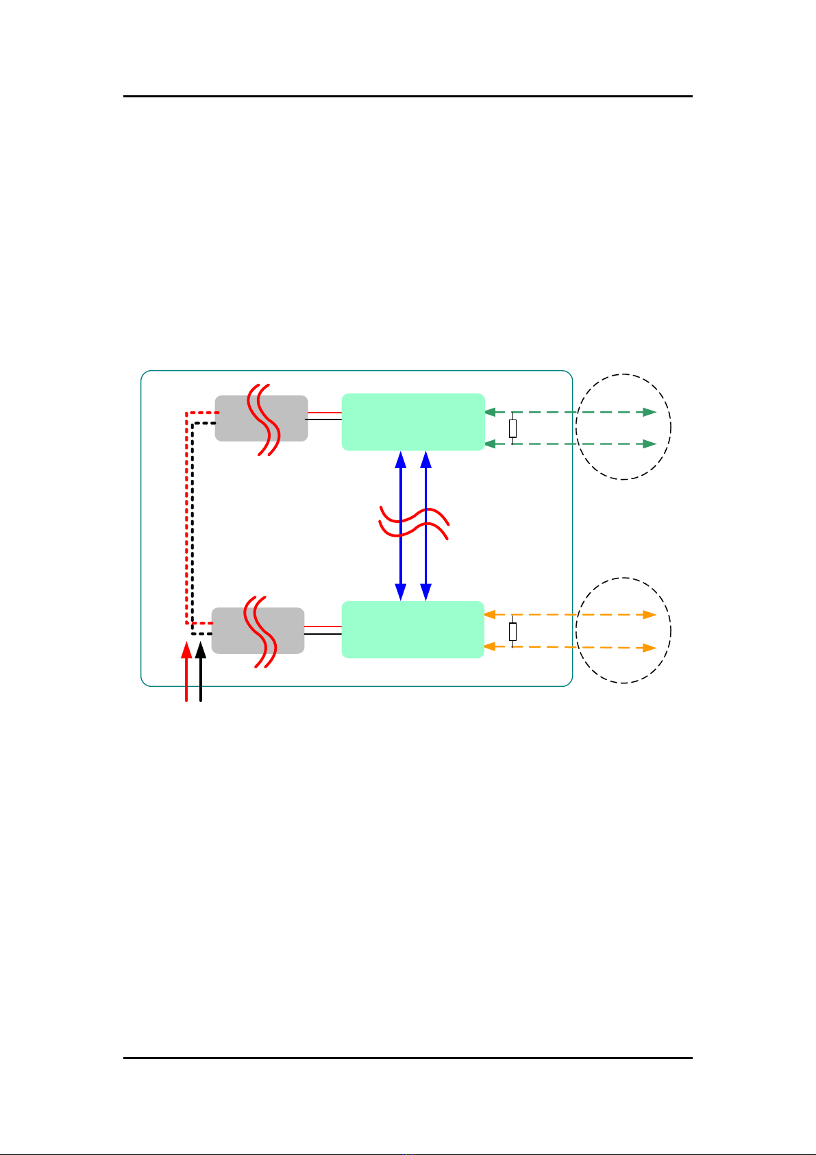
3.1 Block Diagram................................................................................5
3.2 Appearance ....................................................................................6
3.3 Pin Assignment..............................................................................7
3.4 Wire Connection ............................................................................9
3.5 Status LED....................................................................................10
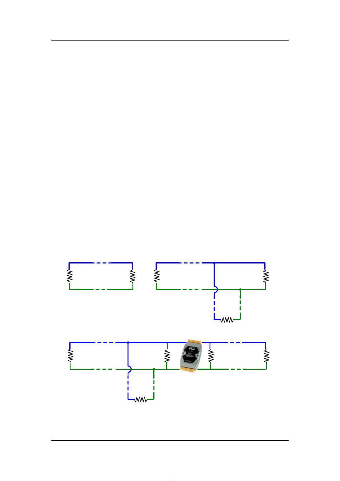
3.6 Terminator Resistor Setting........................................................10
3.7 Cable Selection ............................................................................12
3.8 Driving Capability and Baud Rate ..............................................13
4Application Architecture ......................................................................15
5Dimension and Mounting.....................................................................16
I-7531 CAN Repeater User Manual (ver. 1.5, 2012/11/22) ------2
ГК Атлант Инжиниринг – официальный представитель вРФ иСНГ

2 Introduction
The I-7531 is a CAN repeater used to establish a physical coupling of two
or more segments of a CAN bus system. User can implement tree or star
topologies as well as for long drop lines with I-7531. Connecting via I-7531, the
division of a CAN system into several subsystems increases the maximum
number of bus nodes.
Figure1. Application of I-7531
The I-7531 is an optically isolated CAN repeater which provides 2500 Vrms
optical isolation allowing you to separate and protect critical segments of the
system from the rest of the CAN network. And its galvanic isolation isolates
both CAN segments from each other as well as from the power supply. The
CAN connection of I-7531 is by terminal blocks. A power supply of 10 ~ 30 VDC
is required. The I-7531 is housed in a rugged DIN-Rail mountable box, making
it easy to install in an industrial cabinet. Therefore, I-7531 can be used in
CANopen, DeviceNet and generic ISO 11898-2 standard.
If user wants to know more detail information about the I-7531, please visit
our website as follow:
http://www.icpdas.com/products/Remote_IO/can_bus/i-7531.htm
I-7531 CAN Repeater User Manual (ver. 1.5, 2012/11/22) ------3
ГК Атлант Инжиниринг – официальный представитель вРФ иСНГ

2.1 Features
zHigh speed
zRemovable terminal block
zMountable on DIN Rail
zBus pins protected against transients in an industrial environment
zNo disturbance of the bus lines with an un-powered node
zTransmit data (TxD) dominant time-out function prevents the output
drivers from driving a permanent dominant state
zA thermal protection circuit is integrated to prevent the transceiver
from damage if the junction temperature exceeds thermal shutdown
level.
2.2 Specifications
zSupport CAN 2.0A/CAN 2.0B
zFully compatible with ISO 11898-2
zMaximum communication baud : 800Kbps
zPropagation Delay: ~200ns
zDriving capability: Up to 100 nodes on each CAN port
zPhoto-coupler isolation between 2 CAN ports: 2500 Vrms
zPower consumption: 2W max
zCAN terminal resistors are integrated (can be disabled by jumper)
z3KV galvanic isolated among of power supply and each CAN port
zPower Supply: +10VDC ~ +30VDC
zOperating temperature: -25°C ~ +75°C
zHumidity: 5% ~ 95%
zDimensions: 122 mm x 72 mm x 35 mm
2.3 Application
zFactory Automation
zBuilding Automation
zHome Automation
zVehicle Automation
zControl system
zMonitor system
z…
I-7531 CAN Repeater User Manual (ver. 1.5, 2012/11/22) ------4
ГК Атлант Инжиниринг – официальный представитель вРФ иСНГ

3 Technical data
3.1 Block Diagram
Figure 2 is a block diagram illustrating the functions of the I-7531 module.
Power supply are with 3000 VDC galvanic isolated between each CAN port.
Futhermore, there is photo-isolation 2500 Vrms between two CAN ports.
2500 Vrms
Photo Isolation
DC
DC
3000 VDC
Isolation
DC
DC
3000 VDC
Isolation
+10 VDC ~ +30 VDC
Figure2. Block Diagram of I-7531
Block Diagram of I-7531
CAN_L
120 Ohm
CAN_H
CAN_H
CAN_L
Physical CAN layer
120 Ohm
Physical CAN layer
CAN Port 1
CAN Port 2
I-7531 CAN Repeater User Manual (ver. 1.5, 2012/11/22) ------5
ГК Атлант Инжиниринг – официальный представитель вРФ иСНГ

3.2 Appearance
Figure3. Apperance of I-7531
Power Input
CAN Port 1
CAN Port 2
Status LED of Power
& Communication
i-7531
CAN bus Repeater
‧Support CAN 2.0A/2.0B
‧Photo-isolation: 2500 Vrms
‧Expand the number of CAN buses
‧Mountable on DIN Rail
3000V Isolation
GND
11
(CAN)
20 CAN_L
CAN_H
FG
GND
10
(CAN)
1
CAN_L
CAN_H
FG
(R)VS+
(B)GND
Frame Ground
Frame Ground
I-7531 CAN Repeater User Manual (ver. 1.5, 2012/11/22) ------6
ГК Атлант Инжиниринг – официальный представитель вРФ иСНГ

3.3 Pin Assignment
Figure4. Pin Aassignment of I-7531
Table1. Pin Description of I-7531
No. Part Name Description
1 CAN_L CAN_Low. Signal Line of CAN port 1.
3 CAN_H CAN_High. Signal Line of CAN port 1.
5
CAN
Port 1
GND CAN_Ground (or CAN_GND), Voltage level of
ground of CAN_L and CAN_H of CAN port 1.
7 FG FG Frame Groud.
9 (R)VS+ Voltage Source. It could be +10VDC ~ +30VDC.
10
Power
Input (B)GND Power Ground.
14 FG FG Frame Groud.
16 GND
CAN_Ground (or CAN_GND), Voltage level of
ground of CAN_L and CAN_H of CAN port 2.
18 CAN_H CAN_High. Signal Line of CAN port 2.
20
CAN
Port 2
CAN_L CAN_Low. Signal Line of CAN port 2.
GND
11
(CAN)
20 CAN_L
CAN_H
FG
GND
10
(CAN)
1
CAN_L
CAN_H
FG
(R)VS+
(B)GND
I-7531 CAN Repeater User Manual (ver. 1.5, 2012/11/22) ------7
ГК Атлант Инжиниринг – официальный представитель вРФ иСНГ

Note 1: In some cases, the voltage level of CAN_GND of different CAN
device in the same CAN bus system are not equal. At this time, it
could cause some problems to derogate system staibility of this
CAN bus system.
There is one way to relieve this situation; user can connect the
CAN_GND between those CAN devices to achieve equal
voltage level of CAN_GND.
Wiring of CAN_GND is not necessary; user can modify the
configuration of wiring according to actual applications.
Note 2: Electronic circuits are constantly vulnerable to Electro-Static
Discharge (ESD), which become worse in a continental climate
area. FG(Frame Ground) provides a path for bypassing ESD to
earth ground, allowing enhanced static protection (ESD)
capability and ensures that the module is more reliable.
If user wants to use FG, both the Pin 7 and Pin 14 should be
connected to earth ground. Within the I-7531, Pin 7 and Pin 14
(FG) are not interconneced.
I-7531 CAN Repeater User Manual (ver. 1.5, 2012/11/22) ------8
ГК Атлант Инжиниринг – официальный представитель вРФ иСНГ

3.4 Wire Connection
Figure5. Wire Connection of I-7531
CAN DEVICE
CAN_H
CAN_L
Power GND
+10VDC ~ +30VDC
CAN Port 2
CAN Port 1
CAN_H
CAN_L
CAN_GND
CAN_GND Earth Ground
1
5
6
9
Power
Earth Ground
I-7531 CAN Repeater User Manual (ver. 1.5, 2012/11/22) ------9
ГК Атлант Инжиниринг – официальный представитель вРФ иСНГ

3.5 Status LED
When user turning the I-7531 on, the status LED of I-7531 will be display
with red light. Moreover, when a message passes through I-7531, the status
LED will be twinkle once with yellow light while the red light is still on.
Note 3: Twinkling rate correlates with baud rate of CAN bus. User may see
no twinkling when the twinkling period is too short because of the
higher baud rate of CAN bus. Besides, the yellow LED could look
like always on when bus loading is heavy.
3.6 Terminator Resistor Setting
According to the ISO 11898-2 specifications, the bus line of CAN_H and
CAN_L must be terminated by resistor for proper operation. The equivalent
resistance between CAN_H and CAN_L should be 60Ω. There are some
examples below.
Figure6. Terminator Resistor
Case1: RT= 120ΩCase2: RT= 180Ω
RT
CAN_H
RT
CAN_L
Case3: RT1 = 180Ω, RT2 = 120ΩRT
RT
CAN_H
RT
CAN_L
CAN_H
RT1
CAN_L
RT1
RT1 RT2
RT2
I-7531 CAN Repeater User Manual (ver. 1.5, 2012/11/22) ------10
ГК Атлант Инжиниринг – официальный представитель вРФ иСНГ

On the other hand, the I-7531 module include two build-in 120Ω
terminator resistors, user can decide to enable those two terminator resistors
or not.
The JP2 of I-7531 is used for adjusting terminal resistor on CAN Port 1,
and the JP3 of I-7531 is used for adjusting terminal resistor on CAN Port 2.
Before adjusting JP2 or JP3 of I-7531, user needs to open the cover of
I-7531 first. Those locations of JP2 and JP3 are shown as following:
Figure7. JP2 and JP3 positions
The following connection statuses present the condition if the terminal
resistor is enabled (default) or disabled.
Figure8. Adjustment of Terminator Resistor
Disable
(Deactivate)
Enable
(Activate)
JP2 JP3
CON1 CON2
I-7531 CAN Repeater User Manual (ver. 1.5, 2012/11/22) ------11
ГК Атлант Инжиниринг – официальный представитель вРФ иСНГ

3.7 Cable Selection
The CAN bus is a balanced (differential) 2-wire interface running over
either a Shielded Twisted Pair (STP), Un-shielded Twisted Pair (UTP), or
Ribbon cable.
The table below show recommended DC parameters of CAN bus line.
Table2. Recommended DC parameters for CAN Bus Line
Wire Cross-Section [mm2] Resistance [Ω/km]
~0.25 (AWG23) < 90
~0.5 (AWG20) < 50
~0.8 (AWG18) < 33
~1.3 (AWG16) < 20
The recommended AC parameters of CAN bus line are 120Ωimpedance
and 5 ns/m specific line delay.
I-7531 CAN Repeater User Manual (ver. 1.5, 2012/11/22) ------12
ГК Атлант Инжиниринг – официальный представитель вРФ иСНГ

3.8 Driving Capability and Baud Rate
The relationship between ideal total bus length and baud are displayed
below.
Table3. Baud, Total Bus Length, and Number of I-7531
Baud [bit/sec] Ideal Bus Length without I-7531 [m] Max I-7531 Number
800K 50 1
500K 100 2
250K 250 6
125K 500 12
50K 1000 25
20K 2500 62
10K 5000 125
Note 4: When users add one I-7531 into a CAN network, the ideal total bus
length will reduce 40 meters because of the propagation delay of
I-7531. For example, if users use baud 500K and one I-7531, the
ideal total bus length will be “100 – 40 * 1 = 60 meters“.
After deciding the number of I-7531 and calculating the corresponding
ideal bus length, users can use the following table to know the maximum node
number in each segment and the maximum segment length when using
different type of wire.
Table4. Driving Capability
The maximum segment length [m] under the
case of specific node number in this segment
Wire Cross-
Section [mm2]
16 Nodes 32 Nodes 64 Nodes 100 Nodes
~0.25 (AWG23) <220 m <200 m <170 m <150 m
~0.5 (AWG20) <390 m <360 m <310 m <270 m
~0.8 (AWG18) <590 m <550 m <470 m <410 m
~1.3 (AWG16) <980 m <900 m <780 m <670 m
I-7531 CAN Repeater User Manual (ver. 1.5, 2012/11/22) ------13
ГК Атлант Инжиниринг – официальный представитель вРФ иСНГ

Note 5: The definition of segment and the relationship between segment
length (Lseg1, Lseg2 …) and ideal total bus length (Ltotal) are shown in
the following figure.
Figure9. Definition of Lseg1 and Ltotal
I-7531 I-7531
L1
L2a
L3
L2b
L4
I-7531
Segment 1 Segment 2 Segment 3
Segment 4
Lseg1 = L1
Lseg2 = L2a + L2b
Lseg3 = L3
Lseg4 = L4
Ltotal = Lseg1 + Lseg2 + Lseg3 + Lseg4
I-7531 CAN Repeater User Manual (ver. 1.5, 2012/11/22) ------14
ГК Атлант Инжиниринг – официальный представитель вРФ иСНГ

4 Application Architecture
Figure10. Application Architecture
I-7531 CAN Repeater User Manual (ver. 1.5, 2012/11/22) ------15
ГК Атлант Инжиниринг – официальный представитель вРФ иСНГ

5 Dimension and Mounting
Figure11. Dimension
I-7531 CAN Repeater User Manual (ver. 1.5, 2012/11/22) ------16
ГК Атлант Инжиниринг – официальный представитель вРФ иСНГ

Figure12. Assembly Drawing
Figure13. Mounting
I-7531 CAN Repeater User Manual (ver. 1.5, 2012/11/22) ------17
ГК Атлант Инжиниринг – официальный представитель вРФ иСНГ
Other manuals for CAN Repeater I-7531
3
Table of contents
Other ICP DAS USA Repeater manuals

ICP DAS USA
ICP DAS USA CAN Repeater I-7531 User manual

ICP DAS USA
ICP DAS USA I-7531-FD User manual

ICP DAS USA
ICP DAS USA I-7531-FD User manual

ICP DAS USA
ICP DAS USA I-7531-FD User manual

ICP DAS USA
ICP DAS USA ZB-2510 User manual

ICP DAS USA
ICP DAS USA CAN Repeater I-7531 User manual

ICP DAS USA
ICP DAS USA ZT-2510 Series User manual

ICP DAS USA
ICP DAS USA CAN Repeater I-7531 User manual