COMMON QUESTIONS AND ANSWERS
Q_
Am
a_
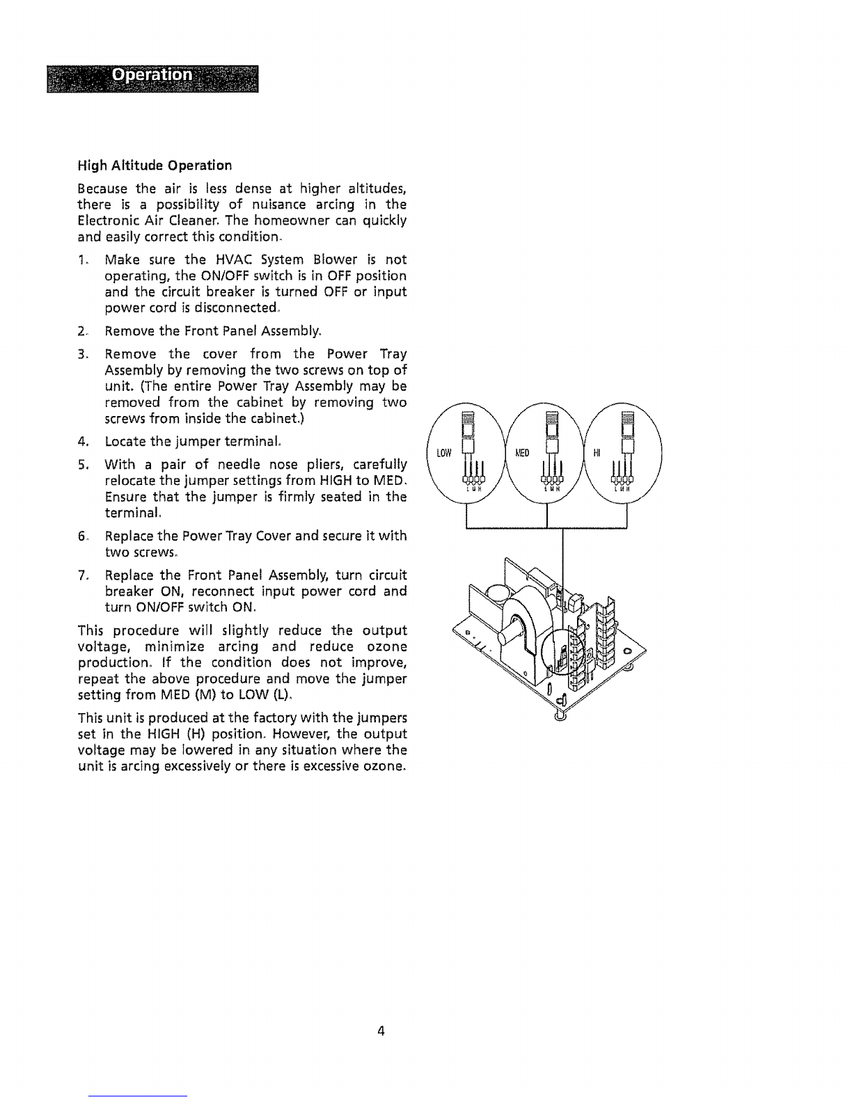
A,
a_
A_
Q.
Ao
Q,
Ao
a_
A_
Why isn't my Electronic Air Cleaner cleaning my air?
The air cleaner is most likely working just like it was designed, However, many
factors can affect the performance of the unit_ Are air return registers located in
the ceiling? If so, it will be difficult for the air flow to carry heavier particulates to
the air cleaner. If the dirt does not get to the air cleaner, it cannot be removed
from the air. Are both the Red and Green indicating lights illuminated? If not, the
unit may be in need of servicing.
It still isn't cleaning my air the way 1want it to, What can 1do?
It is recommended that you operate the HVAC system continuously so that the air
movement will carry the dirt to the air cleaner where it can be collected.
Unfortunately, there will always be some dirt that is left behind on the appliances,
furniture, etc. Regular dusting is recommended to stir up these pockets of dust so
that they can enter the air stream and be removed by the Electronic Air Cleaner.
When t turn on my Electronic Air Cleaner, the lights come on for a couple of
seconds and then turn off. The air cleaner isn't working!
The air cleaner is operating properly as long as both the Red and Green indicating
lights are illuminated. Try turning the HVAC blower ON and then turning the
Electronic Air Cleaner ON_This should solve the problem
What is the zapping noise I am hearing from my unit? Should I be concerned?
The zapping or popping noise that you are hearing isthe sound of larger particles
being "vaporized" by the Ionizing-Collecting Cel!oThis is normal and is no cause
for alarm_ As your HVAC system blower moves the air through the ductwork and
allows the Electronic Air Cleaner to clean the air, the noise will diminish, However,
there will always be instances when larger particles enter the Ionizing-Collecting
Cell, and are "vaporized",
Should 1hear this zapping noise all the time?
All Electronic Air Cleaners will occasionally zap or pop as larger particles pass
through the lonizing_Colfecting Ceils° However, if the sound is constant or is
repetitive in nature, then a large particle may have become lodged in the lonizing_
Collecting cell and may require removal by cleaning, If cleaning the Ionizing-
Collecting Cell does not stop the noise and/or there are no large particles trapped
in the ionizing-Collecting Cell, then the cause could be a broken/loose ionizing
wire, bent collector plate or other mechanical fault.
What if I no longer hear any popping or zapping noises coming from my unit? Is
it still cleaning the air?
tf the zapping noises stop and the air cleaner is not in need of servicing, then one
of two situations has occurred_ First, the Electronic Air Cleaner has successfully
removed all larger particles from the air and is cleaning microscopic particles
which do not cause the zapping noises° Second, the HVAC system blower is not
operating and air is not flowing through the ductwork_ The Electronic Air Cleaner
cannot remove particles if the air stream is not moving.