ICP PGX3 Series User manual

Installation Instructions
PGX3 Series
PACKAGED GAS /ELECTRIC UNITS
TABLEOFCONTENTS
UNITDIMENSIONS ...................................... 2 - 3
SAFEINSTALLATIONREQUIREMENTS ......................... 4
LOCATINGTHE UNIT ....................................... 5
CLEARANCES ............................................ 5
INSTALLATION............................................ 5
GROUNDLEVELINSTALLATION .............................. 5
HOISTING................................................ 6
DOWNFLOWCONVERSION.................................. 6
HEATINGVENTASSEMBLY.................................. 6
CONDENSATEDRAIN....................................... 7
PRE-EXISTINGCOMMONVENTCHECK......................... 7
GASSUPPLYAND PIPING ................................... 7
ORIFICES............................................... 8
ELECTRICALWIRtNG.................................. 10
DUCTWORK......................................... 11
FILTERS ............................................ 11
AIRFLOWADJUSTMENT ............................... 12
START-UPPROCEDURES .............................. 13
GAS PRESSURES .................................... 14
HEATINGSTART-UPPROCEDURES ...................... 14
OPERATION......................................... 16
MAINTENANCE ...................................... 16
INSPECTIONANDCLEANING............................ 17
COMPONENTLOCATION ............................... 18
RIGGING ........................................... 19
WIRINGDIAGRAMS ................................ 20 - 21
CQUS
LISTED
InternationalComfortProducts,LLC
Lewisburg,TN. 37091
462 01 1201 00 1-10-06
Printed in U.S.A.
Code: PGX3

1. Unit Dimensions "B" CHASSIS UNIT DIMENSIONS
COMBINATION GAS/
DIM=
A
B
C
D
E
F
G
H
I
J
K
L
M
N
P
Q
R
S
Units in "B" Chassis Configuration
ELECTRIC UNITS PGX324 -36
"B" Chassis
(473/8 x 473/8) "0" _ "B"
INCHES MILLOMETERS
32-1/2 826
47-3/8 1203
47-3/8 1203
3-1/8 79
11-1/8 283
12 306
14-1/4 383 _ _
14-1/4 363 _ _
12 308 "4 _ _1 'w'
4 102 "1''/
314 I19 28
4-1/4 lO8 [ o \ _ _ ;'E'_
12-1/4 311 //_ _..J _/ j'G_._ T _ '_
12-1/8 308 //_'U'_'" _ "H" -">,/ /
14-1/4 363 / / _ _ ' _
12-1/4 318 i_--_ ._--'/_
/
2-1/2" I
A 1/2" (12.7) CONDUIT \ _/ _i,, _ _ _ // _
1--1/2" "d"
(53975) __ '_L"_ _ _ //_¢ \
.-li8 _ _._ /_'__ _ /_ ..X._/_-- \
(282.575) (101.6) _
ROOF CURB Unit Base shown separately to •
for units in illustrate bottom of duct openings,
"B" Chassis
(473/8 x473/8) Units in "B" Chassis Configuration_
,.c,Es M......... s PGX324 -36 _ _.
42-3/4 1086 /_ _x
39-3/4 1010 _ _
18 457 // _ _._.
18 457 _ _
3-3/4 95 _/ /_/._..._
42-3/4 1086 _ _ /_ _._
"F'_ 8o:_o:12
DIM.
A
B
C
D
E
F
G
H
K*
*Roof curbs are also available in 8" (203) and 24" (610) heights (K Dimensions),
EJ

"C" CHASSIS UNIT DIMENSIONS
1/2"
COMBINATION GAS/
ELECTRIC UNITS
"C" Chassis
(473/8 x 73)
DIM INCHES MILLOMETERS
A 36 914
B 47-3/8 1203
C 73 1354
D 4-5/8 117
E 15 361
F 12 307
G 18-3/4 476
H 18-3/4 476
I 12 306
J 4 102
K 1 &1-1/4 25&31
L 4-1/4 108
M 5-1/4 133
N 12-1/4 311
P 19 483
Q 15 381
R 19 483
S 12-1/4 318
T 16-7/8 429
ROOF CURB
for
"C" Chassis
(473/8 x 73)
_IM INCHES MgLLIM_T_RS
A 67-3/4 1721
B 64-3/4 1645
C 23 584
D 23 584
E 2-1/2 64
F 42-3/4 1086
G 39-3/4 1010
H 23 584
I 12 305
J 12 305
K* 14 356
CAL POWER
CONDUIT ('K" DIM.)
VOLTAGE
1/2" (12.7) CONDUIT
GAS CONNECTION
1/2" (12,7) PIPE
,,p,,
Units in "C" Chassis Configuration
PGX342-60
Unit Base shown separately to
illustrate bottom of duct openings,
* Roof curbs are also available in 8" (203) and 24" (610) heights (K Dimensions),
13

2. SAFE INSTALLATION REQUIREMENTS
Installation and servicing of air-conditioning equipment can
be hazardous due to system pressure and electrical
components. Only trained and qualified personnel should
install, repair, or service air-conditioning equipment.
Untrained personnel can perform basic maintenance
functions of cleaning coils and filters. All other operations
should be performed by trained service personnel. When
working on air-conditioning equipment, observe
precautions inthe literature, tags, and labels attached to the
unit, and other safety precautions that may apply.
Follow all safety codes. Wear safety glasses and work
gloves. Use quenching cloth for unbrazing operations.
Have fire extinguisher available for all brazing operations.
FIRE, EXPLOSION, ELECTRICAL SHOCK, AND
CARBON MONOXIDE POISON HAZARD
Improper installation, adjustment, alteration, service,
maintenance, or use can cause carbon monoxide
poisoning, fire, or an explosion which could result in
personal injury or unit damage. Consult a qualified
installer, service agency, or gas supplier for information
or assistance. The qualified installer or agency must use
only factory-authorized kits or accessories when
modifying this product.
FIRE, EXPLOSION, ELECTRICAL SHOCK, AND
CARBON MONOXIDE POISON HAZARD
Failure to follow this warning could result in personal
injury, death and/or property damage.
Before performing service or maintenance operations
on unit, turn off gas supply to unit. Then turn off unit main
power switch and install lockout tag.
Recogniz_ safety information. This is the safety-alert
symbol/.rX. When you see this symbol in instructions or
manuals, be alert to the potential for personal injury.
Understand the signal words DANGER, WARNING,
CAUTION, and NOTE. These words are used with the
safety-alert symbol. DANGER identifies the most serious
hazards which will result in serious injury or death.
WARNING signifies a hazard which could result in serious
injury or death. CAUTION is used to identify unsafe
practices which may result in minor personal injury or
product and property damage. NOTE is used to highlight
suggestions which will result in enhanced installation,
reliability, or operation.
These instructions cover minimum requirements and
conform to existing national standards and safety codes. In
some instances, these instructions exceed certain local
codes and ordinances, especially those that may not have
kept up with changing residential construction practices.
We require these instructions as a minimum for a safe
installation.
FIRE, EXPLOSION, ELECTRICAL SHOCK, AND CARBON
MONOXIDE POISON HAZARD
Failure to carefully read and follow all instructions in this
manual could result in furnace malfunction, property
damage, personal injury and/or death.
Installation or repairs made by unqualified persons can
result in hazards to you and others. Installation MUST
conform with local building codes or, in the absence of
local codes, with the National Fuel Gas Code NFPA
54-2005/ANSI Z223.1-2005 and the National Electrical
Code NFPA70-2005 or in Canada the National Standard
CAN/CGA B149-1 and CSA C.22.1 -Canadian Electrical
Code Part 1.
The information contained in this manual is intended for
use by a qualified service technician familiar with safety
procedures and equipped with the proper tools and test
instruments.
SAFETY CONSIDERATIONS
• Use only with type of gas approved for this unit. Refer to
unit rating plate.
• Install this unit only in a location and position as specified
in section 3 of this manual.
• Never test for gas leaks with an open flame. Use a com-
mercially available soap solution made specifically for the
detection of leaks to check all connections, as specified in
section 5.
•Always install unit to operate within the unit's intended
temperature-rise range with a duct system, which has an
external static pressure within the allowable range, as
specified in section 9. Refer to unit rating plate for the al-
lowable external static pressures.
•All connecting ductwork to the unit (supply and return)
must be sealed to the unit casing as specified in section 7.
• Do NOT use this furnace as a construction heater.
•Check to see that filters are installed correctly and are the
proper type an size.
NOTE: It is the personal responsibility and obligation of the
customer to contact a qualified installer to ensure that the
installation is adequate and conforms to governing codes
and ordinances.
UNIT SAFETY
Failureto follow this caution may reduceunit reliability.
It is recommended that a qualified service technician
check the heat exchanger integrity everytwo (2) years,
after the first four (4) years of operation.
INTRODUCTION
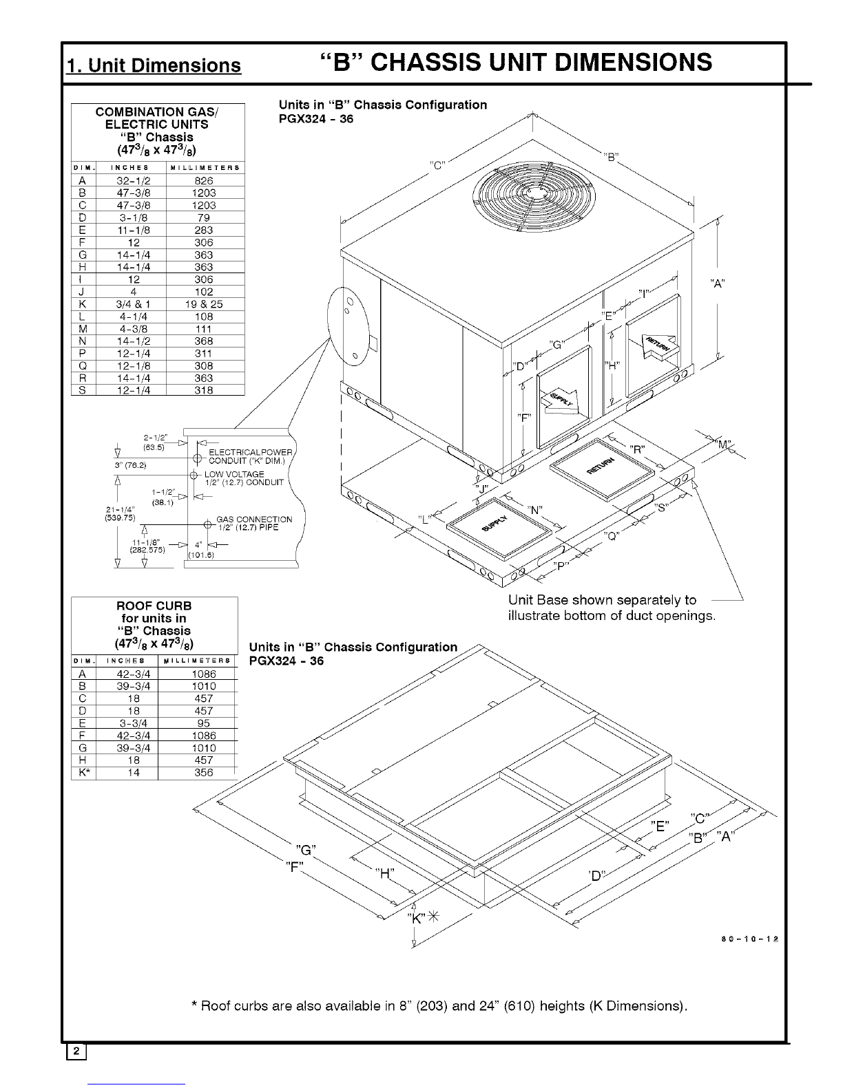
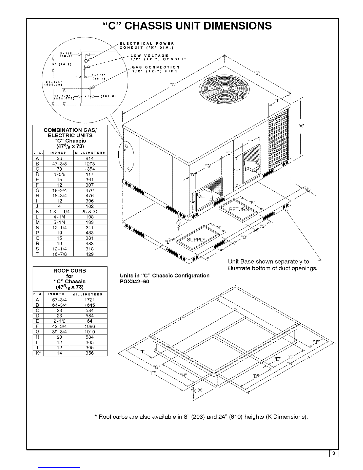
The PGX3 unit is a fully self-contained, combination
Category I gas heating/electric cooling unit designed for
outdoor installation (See pages 2 and 3 for unit
dimensions). All unit sizes have return and discharge
openings for both horizontal and downflow configurations,
and are factory-shipped with all downflow duct openings
covered.
Units may be installed either on a rooftop, cement slab, or
directly on the ground if local codes permit.
Models with a'l" in the twelfth position ofthe model number
are dedicated Low NOx units designed for California
installations. The emissions ofthese models do not exceed
40 nanograms of nitrogen oxide emissions per joule of heat
output as shipped from the factory, and must be installed in
California Air Quality Management Districts or any other
regions in North America where a Low NOx rule exists.
141

FiGuRE iMinimum Clearances and AccessPanels(BChassis Shown)
3. LOCATING THE UNIT
ACCESS PANELS
See Figure 1 for a general view of unit and location of
access panels.
CLEARANCES
The location MUST allow for minimum clearances and
should not be adjacent to a patio or other area where the
unit's operating sound level might be objectionable. The
combustion air inlet openings MUST not be obstructed (see
Figure 1). In addition, local codes MUST be observed.
NOTE: Units with available filter racks (3-1/2 to 5ton), need
a 26" minimum clearance at side of unit for removal of
filters. See chart below if unit is going to be placed near
combustible construction or materials.
While minimum clearances are acceptable for safety
reasons, they may not allow adequate air circulation around
the unit for proper operation inthe cooling mode. Whenever
possible, it is desirable to allow additional clearance,
especially around the condenser inlet and discharge
openings.
Do NOT install the unit in a location that will permit
discharged air from the condenser to recirculate to the
condenser inlet.
UNIT DAMAGE HAZARD
Failure to follow this caution may result in shorten life
of unit components.
Do NOT operate unit in a corrosive atmosphere
containing chlorine, fluorine, or any other corrosive
chemicals.
Minimum Clearances to Combustible Construction
Furnace Plenum ..................................... 2"
Duct Side ........................................... 2"
Condenser Inlet .................................... 30"
Blower Service (Side) ............................... 30"
Control Service Side
(Front Combustion Air Inlet) .............. 30"
Clearance between 3 Ft. Overhang
and Top of Unit ......................... 30"
Combustible Base
(Wood or Class A, B or C
roof covering material) ..................... 0"
IBlower Compartment Panel
B Chassis - 2"
C Chassis - 6"
Internal Filter Access
from Burner Compartment Side
26" (C Chassis Units) Burner Compartment
Panel
INSTALLATION NOTICE
Unit will NOT operate properly unless it is installed
level front to rear and side to side. The slope MUST NOT
be greater than 1/8" per foot (10mm per meter). For side
to side leveling, the drain side MUST always be lower.
Ground Level Installation
Ground level platform requirements:
- The unit MUST be situated to provide safe access for
servicing.
- Platform may be made of either concrete or pressure
treated wood and MUST be level and strong enough to
support unit weight.
- Position platform separate from building foundation.
- Install in well-drained area, with top surface of platform
above grade level.
- Platform must be high enough to allow for proper
condensate trap installation and drainage. See
FIGURE 4 and associated text for more information
about condensate drainage.
151

Rooftop Installation
Rooftop platform requirements:
- The unit MUST be situated to provide safe access for
servicing.
- The existing roof structure MUST be adequate to
support the weight of the unit or the roof MUST be
reinforced.
Check the weight of the unit in relation to the roof
structure and local building codes or ordinances and
reinforce roof structure if necessary. See the last page
of this manual for unit weights.
- Support for the unit MUST be level and strong enough
to carry unit weight. The support may consist of a
platform or a combination of platform and roof beams or
curb.
- See Hoisting section for hoisting instructions,
HOISTING
NOTE: All access panels MUST be secured in place before
hoisting.
The unit should be hoisted with two lifting slings. Attach the
slings to rigging shackles that have been hooked through
holes in the base rail,
Two spreader bars MUST be placed on top of the unit to
protect the unit from damage from the pressure exerted by
the slings. Make sure that all equipment is adequate to
handle the weight ofthe unit and that the slings will not allow
the unit to shift.
Refer to FIGURE 18 on the back cover of this manual for
illustrated rigging instructions and weight chart,
DOWNFLOW CONVERSION
NOTE: In downflow applications with roof curbs or jack
stands, the center rail under the unit must be removed. The
center rail is attached to the base rail with screws.
These units are adaptable to downflow use, To convert to
downflow use, follow these steps:
1. Remove the blockoff plates found in the return air
compartment and the supply air compartment.
NOTE: Blockoff plate in the supply air compartment only
contains one screw. If reinstalling plate, back part of plate
MUST fit into mating dimples on flange. To reinstall, slant
plate into dimples, then put plate into position and fasten
with screw.
I FIGURE2 1 Heating Vent Assembly
Screws for Screw for
"B" Chassis "C" Chassis
(473/8 x 473/8) (473/8 x 73)
I
2. Install the removed plates on the horizontal return and
supply air openings.
3, Install roof curb on the building. Be sure to follow all
directions included with curb and all applicable building
codes in your installation. See page 2 or 3 for
appropriate roof curb to use.
Heating Vent Assembly
The flue cover is packed with installation screws in the
return air compartment, Refer to FIGURE 3 and assemble
as shown,
FIGURE 31 Heating Vent Assembly
Flue Support
(Shipped mounted to unit
Flue Cover
UNIT DAMAGE
Failure to follow this caution may result in unit
damage.
Do not operate the unit without the vent assembly
installed.
161

Condensate Drain
The condensate drain outlet is a 3/4" (19.1mm) female PVC
connection located atthe bottom ofthe unit tothe right ofthe
filter access panel (see FIGURE 4).
The circulating blower creates a negative pressure on the
condensate drain line that can prevent the condensate from
draining properly. To combat this negative pressure, a field
supplied condensate trap that will allow a standing column
of water of at least 2" (50.8mm) MUST be installed. Top of
outlet from trap MUST be at least 1" (25.4mm) below top of
outlet from unit. Install the trap as near to the unit as
possible for proper drainage.
A3/4" (19.1mm) drain line MUST be installed if required by
local codes or if location of unit requires it. Run the drain line
to an open drain or other suitable disposal point.
FIGURE 4 Condensate Drain Information*
b
25-1/2 ("B" Chassis)
32-1/4 ("C" Chassis)
3/4" (19,1mm)
Threaded Female
PVC Fitting
1 "
(25.4mm)
/
2" (5O.8mm)
80-30-27
*Condensate trap MUST be installed,
4. PRE-EXISTING COMMON VENT CHECK
If the installation of this new combination gas heat/electric
cool unit involves removing an existing gas-fired furnace
from a common vent system with other gas-fired
appliances (gas-fired hot water heater, etc.), the existing
vent system must be checked and inspected by a qualified
technician. The qualified technician can determine if the
existing vent system will properly vent the flue products of
the remaining gas-fired appliances. In many cases, the
existing vent system may be oversized for the remaining
appliances.
5. GAS SUPPLY AND PIPING
NOTE: Because there are many types of liquified petroleum
(LP) gases, the term LP as used in this manual refers to
propane gas. If you intend to use any type of LP gas, proper
precautions MUST be used in the handling, piping, and use
of such gas. NOTE: In Canada, installations MUST be
performed by licensed LP installers.
The UL rating plate located on the side panel on the unit
contains the model number, type of gas, gas input rating,
and other important information.
FIRE OR EXPLOSION HAZARD
Failure to follow this warning could result in personal
injury, death and/or property damage.
Makecertainthe unitisequipped tooperateonthe typeof
gasavailable.Models designatedas natural gasareto be
used with natural gas only. Models designated for use
with liquefied petroleum (LP) gas are shipped with
orifices sized for commercially pure propane gas. They
MUSTnot beusedwith butaneor a mixtureofbutaneand
propane unless properly sized orifices are installed bya
licensed LPinstaller.
GAS PIPING
The gas supply line MUST be of adequate size to handle the
Btu/hr requirements and length of the run for the unit being
installed. Determine the minimum pipe size for natural gas
from the table in FIGURE 5 or FIGURE 6. Base the length
of the run from the gas meter or source to the unit.
Gas Pipe Size
Btu ratings of all other gas appliances MUST be considered
for sizing of main gas line. Check gas line to installation for
compliance with local codes or, in the absence of local
codes, with the National Fuel Gas Code NFPA
54-2005/ANSI Z223.1-2005 or in Canada the National
Standard CAN/CGA B149-1 or current editions.
FIGURE 5Gas Pipe Size, Length and Btu/hr Capacity
for Schedule 40 Iron Pipe/English/
NATURAL GAS
Pipe Length Btu/hr (in thousands)
(includes
Fittings) 3/4" 1" 11/4" 11/2" 2"
20' 190 350 730 1,100 2,100
40' 130 245 500 760 1,450
60' 105 195 400 610 1,150
LP GAS
Pipe Length Btu/hr (in thousands)
(includes
Fittings) 1/2" 3/4" 1" 11/4"
20' 189 393 732 1,496
40' 129 267 504 1,039
60' 103 217 409 834
11/2"
2,299
1,559
1,275
LZJ

FIGURE 6 Gas Pipe Size, Length and Btu/hr Capacity
for Schedule 40 Iron Pipe (English)
NATURAL GAS
Pipe Length kW**
(includes
Fittings) 3/4" 1" 11/4 " 11/2" 2"
6.1m 56 103 214 322 615
12.2m 38 72 147 223 425
18.3m 31 57 117 179 337
LP GAS
Pipe Length kW**
(includes
Fittings) 1/2" 3/4" 1" 11/4 " 11/2 "
6.1m 55 115 215 438 674
12.2m 38 78 148 305 457
18.3m 30 64 120 244 374
**kW (Ki!owatts) is the metric equivalent of Btu/hr.
PIPING AT UNIT
Connections
NOTE: The rules listed apply to natural and LP gas pipe
installations.
1. If installation is for LP gas, have LP gas installer use
TWO-STAGE REGULATION and make all
connections from storage tank to unit.
2. Use black iron or steel pipe and fittings or other pipe
approved by local code.
3. If copper tubing is used, it MUST comply with limitation
set in Fuel Gas Code.
NOTE: If a flexible gas connector is used, it MUST be
acceptable to local authority. Connector MUST NOT be
used inside the furnace or be secured or supported by the
furnace or ductwork. Do not use a connector which has
previously serviced another gas appliance. Always use a
new listed connector.
FIRE OR EXPLOSION HAZARD
Failure to do so could result in personal injury, death
and/or property damage.
Gas connector MUSTbeproperly installedand can NOT
be used inside thefurnace.
4. Use pipe joint compound on external (male) threads
ONLY. Joint compound MUST be resistant to any
chemical action of LP gases. Do NOT put pipe
compound on last 2 threads of pipe.
5. Use ground joint unions and install a drip leg no less
than 3 inches (76 mm) long to trap dirt and moisture
before it can enter gas valve.
TABLE 1 & 2: Equivalent Orifice Sizes at High Altitudes
UNIT OPERATION AND COMPONENT DAMAGE HAZARD
Failure to follow this caution may result in misaligned
burners, flame rollout and or unit damage.
Overtightening assembly may cause damage to the gas
valve and/or wirin_land may misali_lnthe burners.
6. Use a wrench on gas valve when making connections
to prevent gas valve from turning. Do NOT use a pipe
wrench on the gas valve body.
7. Provide a t/8 inch (3mm) National Pipe Thread (NPT)
plug for test gauge connection immediately upstream of
the gas supply connection to the furnace if none is
supplied with the gas valve of unit.
8. Install a manual shutoff valve and tighten all joints
securely.
LEAK CHECK/PRESSURE TESTING OF GAS SUPPLY
PIPING
FIRE OR EXPLOSION HAZARD
Failure to follow the safety warnings could result in per-
sonal injury, death or property damage.
Never test for gas leaks with an open flame. Use a com-
mercially available soap solution made specifically for
the detection of leaks to check all connections. A fire or
explosion may result causing property damage, person-
al injury or loss of life.
The unit and its equipment shutoff valve must be
disconnected from the gas supply piping system during any
pressure testing of that system at test pressures in excess
of .5 psi (3.5kPa).
The unit must be isolated from the gas supply piping system
by closing the equipment shut off valve during any pressure
testing of the gas supply piping system at test pressures
equal to or less than .5 psi (3.5 kPa).
ORIFICES
Orifice Sizes
Orifice sizes MUST be matched to the heating value of the
gas (see TABLE 1 & 2). Check with your gas supplier and
the National Fuel Gas Code ANSI Z223.1.
NOTE: An LP Conversion Kit MUST be used for conversion
to LP gas.
NOTE: For elevations above 2000 feet (610 meters), the
Btu input rating MUST be reduced by 4% for each 1000 feet
(305 meters) above sea level, unless the gas supplier's
Btu!ft3 content has already been adjusted for altitude.
Check Table 1 & 2 for the proper orifice sizes.
Table1NATURALGASORIFICESIZING
MEANELEVATIONFEETABOVESEALEVEL
0to 2000 2001to 4001to 5001to 6001to 7001to 8001to 9001to
4000 5000 6000 7000 8000 9000 10000
Orifice Kit Orifice Orifice Orifice Orifice Orifice Orifice Orifice
NominalHeatingSize Drill # Number Drill # Drill # Drill # Drill # Drill # Drill # Drill #
All Sizes 44 1173863 45 46 47 47 48 48 49

NOTE: The orifice sizes in the chart above derate the input rate at 4% per 1000 feet above sea level for altitudes exceeding 2000 feet
above sea level. If converting from LP gas to Natural Gas at altitudes exceeding 2000 feet above sea level, use part number
330732-401, plus the required orifice size # shown in Table 1. Natural Gas data is based on 0.60 specific gravity, a heating value of 1030
Btu/Cu.Ft., and 3.5" W.C. manifold pressure. For fuels with different specific gravity, consult the National Fuel Gas Code NFPA
54-2005/ANSI Z223.1-2005 or National Standard of Canada, Natural Gas and Propane Installation Code CSA B149.1-05.
Table2 LPGASORIFICESIZING
MEANELEVATIONFEETABOVESEALEVEL
0to2000 2001to4000 40011o7000 7001to9000 90011o10,000
NominalHeating Orifice Kit Orifice Kit Orifice Kit Orifice Kit Orifice Kit
Size Drill # Number Drill # Number Drill # Number Drill # Number Drill # Number
All Sizes 55 1173857 55 1173857 56 1173859 56 1173859 57 1173861
NOTE: The orifice sizes in the chart above derate the input rate at 4% per 1000 feet above sea level for altitudes exceeding 2000 feet
above sea level. LP Gas data is based on 1.52 specific gravity, a heating value of 2500 Btu/Cu. Ft., and 10.0" W.C. manifold pressure. For
fuels with different specific gravity, consult the National Fuel Gas Code NFPA 54-2005/ANSI Z223.1-2005 or National Standard of
Canada, Natural Gas and Propane Installation Code CSA B149.1-05.
Changing Orifices
ELECTRICAL SHOCK, FIRE AND/OR EXPLOSION
HAZARD
Failure to follow this warning could result in personal
injury, death and/or property damage.
Shut off electric power at unit disconnect or service
panel and shut off gas at manual shut off valve before
beginning the following procedure.
Changing orifices requires a qualified service
technician.
1. Shut OFF gas at manual shut off valve.
2, Shut OFF electric power at unit disconnect or service
panel. If unit is still running, allow 3 minutes after gas
shut off before turning off power.
3, Disconnect the wires from the gas valve, sparker, and
flame sensor.
4. Remove the four screws holding the manifold to the
manifold brackets.
5. Carefully remove the manifold with the gas valve
attached.
6, If unit has v-shaped NOx baffles installed in the firing
tubes, they must be removed when coverting to LR
Some baffles may be attached by screws, Replace
screws after removing NOx baffles (figure 7).
FIGURE 7 Removing NOx Baffles
CARBON MONOXIDE HAZARD.
Failure to follow this warning could result in per-
sonal injury death and/or property damage.
NOx baffles for use with Natural Gas units ONLY. If
LP Gas is required, NOx inserts must be removed.
or
25-22-46a
7, Remove the orifices from the manifold with a 7/t6" box
end or socket wrench.
8, Check to be sure that the size of each orifice is correct
for the Btu input desired,
FIGURE8 Manifold/Orifice Measurement
Measure 13/16 " from face of orifice
back edge of manifold pipe.
Install the correct orifices. Gauge the size ofthe orifices
with a new twist drill bit of the correct size.
Make sure that the orifices go in straight so that they
form a right angle (90 °) to the manifold pipe.
Tighten the orifices so that there is a 13/t6" distance
between the faces of the orifices to the back of the
manifold pipe.
Measure the distance with a set of calipers, If you do not
191

have a calipers, you can use an adjustable wrench and
measure between the face of the jaws.
10. Reassemble in reverse order.
6. ELECTRICAL WIRING
ELECTRICAL SHOCK HAZARD.
Failure to follow this warning could result in personal
injury, death, and/or property damage,
The unit cabinet must have an uninterrupted,
unbroken electrical ground to minimize the possibility
of serious injury if an electrical fault should occur.
This ground may consist of an electrical wire
connected to the unit ground lug in the control
compartment, or conduit approved for electrical
ground when installed in accordance with National
Electric Code (NEC) NFPA 70, National Fuel Gas Code
NFPA 54-2005/ANSI Z223.1-2005 and local electrical
codes. In Canada, follow Canadian Electrical Code
CSA (Canadian Standards Association) C22.1 and
local electrical codes.
REDUCED EQUIPMENT LIFE HAZARD
Failure to follow these cautions could result in damage
to the unit being installed.
1) Make all electrical connections in accordance with
National Electric code (NEC) NFPa 70, National Fuel Gas
Code NFPA 54-2005/ANSI Z223.1-2005 and local
electrical codes governing such wiring. In Canada, all
electrical connections must be in accordance with CSA
standard C22.1, Canadian Electrical Code Part 1, and
applicable local codes. Refer to unit wiring diagram.
2) Use only copper conductor for connections between
field-supplied electrical disconnect switch and unit. DO
NOT USE ALUMINUM WIRE.
3) Be sure that high-voltage power to unit is within
operating voltage range indicated on unit rating plate.
4) Do not damage internal components when drilling
through any panel to mount electrical hardware,
conduit, etc. Consult local power company for
correction of improper voltage and/or phase imbalance.
For access, remove the burner access panel. See Figure 1
for access panel location. Wiring MUST be protected from
possible mechanical damage.
Disconnect Switch
The unit must have separate electrical service with a
field-supplied, waterproof, disconnect switch mounted at,
orwithin sight from, the unit. Refer tothe unit rating plate for
maximum fuse/circuit breaker size and minimum circuit
amps (ampacity) for wire sizing.
Ground Connections
Do NOT complete line voltage connections until unit is
permanently grounded. All line voltage connections and the
ground connection MUST be made with copper wire.
A ground lug is installed in the control box area for the
ground connection. Use a copper conductor of the
appropriate size from the unit to a grounded connection in
the electrical service panel or a properly driven and
electrically grounded ground rod. See warning above.
Line Voltage Wiring
Connections for line voltage are made in the unit control box
area. Refer to wiring diagram located on the Burner Access
panel. For access, remove the burner access panel.
1. Run the high voltage (L1, L2) and ground leads into the
control box.
2. Connect ground lead to chassis ground connection.
3. Connect L1 to pressure lug connection 11 of the
compressor contactor.
4. Connect L2 to pressure lug connection 23 of the
compressor contactor.
Thermostat /Low Voltage Wiring
Location of the thermostat has an important effect on home
comfort. FOLLOW THE THERMOSTAT INSTRUCTION
MANUAL FOR CORRECT LOCATION, MOUNTING, AND
WIRING.
A two-stage thermostat is required for proper operation.
Thermostat should have the following terminals: "R",
"W/W1 ", "Y1", "Y2", and "G'. Some electronicthermostats
use low voltage from the unit for power for temperature
display and programming. These electronic thermostats
will have a "C" terminal. The outdoor unit has color-coded
wires for easy connection. Using wire nuts, follow figure 10
for proper connections:
FIGURE 9 Thermostat Connections
,,1_ ed
White
Yellow
Pink
miD" Green
Typical
Mechanical
Thermostat
Subbase
,,1_ Red
White
Y_ _Yellow
Pink
Typical
Electronic
Thermostat
Subbase
THERMOSTAT HEAT ANTICIPATOR
Some thermostats have an adjustable heat anticipator. The
heat anticipator prevents temperature overshoot in heating
mode. If the heat doesn't turn off until the set point
temperature on the thermostat is exceeded, then the
anticipator setting is too low. If the heat turns off before the
thermostat reaches the set point temperature on the
thermostat, then the anticipator setting is too high. Follow
the thermostat instruction manual for proper adjustment of
the heat anticipator.
Final Electrical Check
1. Make a final wiring check to be sure system is correctly
wired. Inspect field installed wiring and the routing to
ensure that rubbing or chafing due to vibration will not
occur.
NOTE: Wiring MUST be installed so it is protected from
possible mechanical damage.

7. DUCTWORK
Ductwork Sizing
The maximum recommended velocity in trunk ducts is 1000
feet per minute. The maximum recommended velocity in
branch ducts is 800 feet per minute.
Ductwork sizing affects the discharge temperature, airflow
velocity, and efficiency of the system. Be sure to properly
size ductwork to the capacity of the unit and to the airflow
requirements of the conditioned space. Failure to properly
size ductwork can result in inadequate airflow and poor
efficiency. Undersized ductwork may result in tripped limit
controls and premature failure of compressors, motors and
other components.
Ductwork Insulation
Ductwork installed outdoors must have a minimum 2" thick
fiberglass "wrap" insulation and a weatherproof vapor
barrier installed around it. The insulation and vapor barrier
must be protected against potential damage. Caulking,
flashing, and other means of providing a permanent
weather seal must be used.
Ductwork Connections
The use of flexible, non-combustible connectors between
main trunk ducts and supply and return air plenums is
FIGURE 10 Filter Sizes
PGX324040K ....
PGX324060K ....
PGX324080K ....
PGX330040K ....
PGX330060K ....
PGX330080K ....
PGX336060K ....
PGX336080K ....
PGX336100K ....
PGX342080K ....
PGX342100K ....
PGX348080K ....
PGX348120K ....
PGX348140K ....
PGX360080K ....
PGX360120K ....
Disposable Filters
Nominal Size
(qty x w x d)
1 x 20" x 20"
1 x 20" x 24"
2 x 15" x 20"
1 x 20" x 24"
1 x 20" x 24"
2 x 15" x 20"
2 x 15" x 20"
2 x 15" x 20"
2 x 18"x20"
2 x 18"x20"
2 x 18"x20"
2 x20" x20"
2 x 20" x 24"
2 x 24" x 24"
2 x 20" x 24"
2 x 20" x 24"
permitted. If flexible connectors are used, they should be
protected from potential mechanical damage such as
punctures and tears.
NOTE: When connecting the supply and return plenums to
the unit, make sure that the plenums are sealed against the
side casing of the unit and do not interfere with removal of
the top of the unit.
FILTERS
Minimum Area
(sq. inches)
384
428
576
480
480
576
576
576
720
672
720
768
854
1008
960
960
All return air MUST pass through a filter before entering the
unit. An electronic air cleaner, optional filter racks, or other
accessible filter arrangement must be installed in the return
air ductwork. Minimum recommended filter sizes are listed
in FIGU RE 10 and are based on maximum face velocities of
300 ft/min for disposable filters and 600 ft/min for washable
(high velocity) filters. See figure 10 for filter sizes.
REDUCED EQUIPMENT LIFE HAZARD
Failure to follow this caution may result in improper
unit operation,
Do not operate the unit without a filter,
Washable Filters"
Nominal Size
(qty x w x d)
1 x 10" x 20"
1 x 12" x 20"
1 x 15" x 20"
1 x 12" x 20"
1 x 12" x 20"
1 x 15" x 20"
1 x 15" x 20"
1 x 15" x 20"
1 x 18" x20"
1 x 18" x20"
1 x 18" x20"
1 x 20" x 20"
1 x 20" x 24"
1 x 24" x 24"
1 x 20" x 24"
1 x 20" x 24"
Minimum Area
(sq. inches)
192
214
288
240
240
288
288
288
36O
336
36O
384
427
5O4
48O
48O
PGX360140K .... 2 x 24" x 24" 1008 1x 24" x 24" 504
1Washable filter size based on an allowable face velocity of 600 ft/min. Refer to
filter manufacturer's specifications for allowable face velocity and required filter area.
L//J

8. AIRFLOW ADJUSTMENT
PGX3SERIESHEATINGCHART
External Static Pressure (in H20)
.1" 2" .3" .4" .5" .6" .T' 8"
Cooling Hea6n0 Input HeatingHise Speed Heating Heatrng Heating Heatln0 Heating Heating Heating Heating
Model Tuns (8tuih0 Range(_F) Tap CFM Rise (°F) CFM Rise(_F) OFM Rise (°F) OFM Rise(_F) CFM Rise (°F) CFM Rise(_F) CFM Rise (°F) OFM Rise(_F)
5 1251 NA /218 NA 1194 NA 1170 NA 1139 NA 1100 NA 1063 NA 988 NA
4 95/ NA 914 NA 883 NA 858 35 811 37 775 38 733 40 697 43
PGX324040K.... 2 40000 35 65 3 869 NA 842 35 809 37 768 39 736 40 684 43 650 46 599 49
2 71I 42 655 45 623 48 564 53 529 56 48I 62 43/ NA 392 NA
/ 66/ 45 4(8 62 334 NA 262 NA 219 NA /96 NA NA NA NA NA
5 /251 36 /218 36 1/94 37 /170 38 1139 39 /I00 40 1063 42 988 45
4 951 47 9/4 49 883 50 858 52 81/ 55 775 57 733 6/ 697 64
PGX32406OK.... 2 60000 35 65 3 869 51 842 58 809 55 768 58 736 69 684 65 650 NA 599 NA
2 711 63 655 NA 623 NA 564 NA 529 NA 48I NA 43I NA 892 NA
/ 66/ NA 4(8 NA 334 NA 262 NA 2/9 NA /96 NA NA NA NA NA
5 /251 47 /218 49 1/94 50 1170 5I 1/39 52 /I00 54 1083 56 988 60
4 95I 62 914 65 883 NA 858 NA 811 NA 775 NA 733 NA 697 NA
PGX32408OK.... 2 80000 35 65 3 869 NA 842 NA 809 NA 768 NA 736 NA 684 NA 850 NA 599 NA
2 71I NA 655 NA 623 NA 564 NA 529 NA 48I NA 43/ NA 392 NA
/ 66/ NA 478 NA 334 NA 262 NA 219 NA /98 NA NA NA NA NA
5 /255 NA /227 NA /20I NA 1164 NA 1138 NA 11/2 NA 1077 NA /027 NA
4 1106 NA /080 NA 1048 NA 1017 NA 992 NA 954 NA 924 NA 881 NA
PGX33O04OK.... 25 40000 35 65 3 958 NA 923 NA 894 NA 857 35 828 36 788 38 750 40 712 42
2 789 38 747 40 714 4/ 668 44 630 47 582 5I 542 55 495 60
1/54 39 /08 42 6/1 44 618 48 584 51 524 5( 494 60 443 NA
5 1255 35 1227 36 120I 37 1164 38 1138 39 /I12 40 1077 4/ /027 43
4 1106 40 1080 4I 1048 42 1017 44 992 45 954 47 924 48 88I 50
PGX33O06OK.... 25 60000 35 65 3 958 46 923 48 894 50 857 52 828 54 786 57 750 59 712 62
2 789 56 747 59 714 62 668 NA 630 NA 582 NA 542 NA 495 NA
1/54 59 /08 63 6/I NA 6/8 NA 584 NA 524 NA 494 NA 443 NA
5 1255 47 /227 48 120I 49 I164 5I 1138 52 /I/2 53 1077 55 /027 58
4 1106 54 /080 55 1048 57 I017 58 992 60 954 62 924 64 88I NA
PGX33OOSOK.... 25 80000 35 65 3 958 62 923 64 894 NA 857 NA 828 NA 788 NA 750 NA 712 NA
2 789 NA 747 NA 714 NA 668 NA 630 NA 582 NA 542 NA 495 NA
1754 NA 708 NA 671 NA 818 NA 584 NA 524 NA 494 NA 443 NA
4 1630 NA 1588 NA /528 NA 1477 NA 1415 NA 1354 NA 1287 35 /216 37
3 /276 35 /242 38 1209 37 /179 38 1150 39 /I/7 40 1086 4/ /045 43
PGX33606OK.... 3 60000 35 65 2 /026 43 994 45 949 47 913 49 87/ 5/ 84I 53 793 56 735 60
1 876 5/ 84I 53 794 56 756 59 894 64 65I NA 598 NA 543 NA
4 1630 36 /588 37 1526 39 I477 40 14/5 42 /354 44 1287 46 /216 49
3 /276 46 /242 48 1209 49 1179 50 1/50 52 /I/7 53 1086 55 /045 57
PGX33608OK.... 3 80000 35 65 2 1026 58 994 60 949 62 913 85 87I NA 84I NA 793 NA 735 NA
/ 8/6 NA 84I NA /94 NA (56 NA 694 NA 65I NA 598 NA 543 NA
4 /630 45 /588 47 1528 49 1477 50 14/5 52 /354 55 1287 58 /216 6I
3 1276 58 1242 80 1209 6/ 1179 83 1150 64 /I17 NA 1086 NA /045 NA
PGX33610OK.... 3 100000 35 65 2 1026 NA 994 NA 949 NA 913 NA 871 NA 84I NA 793 NA 735 NA
/ 8/6 NA 84I NA /94 NA (56 NA 694 NA 65I NA 598 NA 543 NA
5 /589 38 /537 39 1500 40 /463 4I 1423 42 /389 43 1353 44 /317 45
4 /481 40 /448 4I 1412 42 /374 43 1336 44 /298 48 1283 47 /226 48
PGF342089K.... 35 80000 35 65 3 1302 46 /269 47 1219 49 I179 50 1138 52 /I03 54 1060 56 /015 58
2 1170 51 /I29 52 1088 54 I050 58 1007 59 963 82 912 65 888 NA
/ /028 58 969 6I 924 64 881 NA 838 NA 789 NA 73/ NA 680 NA
5 /589 47 /537 48 1500 49 1463 5I 1423 52 /389 53 1353 55 /317 58
4 1481 50 1448 5I 1412 52 1374 54 1336 55 /298 57 1283 59 /226 60
PGX3421OOK.... 35 100000 35 65 3 1302 57 1260 59 1219 6/ 1179 83 1138 65 /I03 NA 1060 NA /015 NA
2 //70 63 /I29 NA /088 NA 1050 NA 1007 NA 963 NA 912 NA 886 NA
1 1028 NA 969 NA 924 NA 881 NA 836 NA /89 NA /31 NA 689 NA
5 2103 NA 205/ NA 200I NA 1942 NA 1878 NA 1809 NA 1723 NA /632 36
4 183I NA /797 NA 1783 NA 1732 NA 1696 35 166/ 38 1621 37 /559 38
PGX34808OK.... 4 80000 35 65 3 /680 35 /850 36 1614 37 1578 38 1544 38 /507 39 1470 40 /427 42
2 /304 45 /256 47 1218 49 1167 5I 1/26 53 /077 55 1026 58 979 6I
1 //f3 51 112/ 53 1085 55 /g2( 58 983 69 92f 64 88I NA 82I NA
5 2103 42 2051 43 200I 44 1942 48 1878 47 /809 49 1723 52 /632 54
4 /83I 49 /797 49 1783 50 /732 5I 1696 52 /66/ 54 1621 55 /559 57
PGX34812OK.... 4 120000 35 65 3 /680 53 /850 54 1614 55 /578 58 1544 58 /507 59 1470 60 /427 62
2 1304 NA /256 NA 1218 NA 1167 NA 1126 NA 1077 NA 1026 NA 979 NA
1 1/73 NA 1127 NA 1085 NA 1027 NA 983 NA 927 NA 881 NA 821 NA
5 2103 49 205/ 5I 200I 52 I942 53 1878 55 /809 57 1723 60 /632 64
4 /83I 57 /797 58 1783 59 1732 80 1696 61 /66/ 62 1621 64 /559 NA
PGX34814OK.... 4 140000 35 65 3 /680 62 /850 63 1614 64 1578 NA 1544 NA /507 NA 1470 NA /427 NA
2 1304 NA 1256 NA /218 NA 1167 NA 1126 NA 1077 NA 1026 NA 979 NA
/ ///3 NA /I2/ NA /085 NA I02( NA 983 NA 92( NA 881 NA 821 NA
5 2/88 NA 2140 NA 2098 NA 2039 NA 1974 NA 1905 NA 1827 NA /745 NA
4 2091 NA 2056 NA 2023 NA 1987 NA 1935 NA 1878 NA 1811 NA /729 NA
PGX36O08OK.... 5 80000 35 65 3 1839 NA /807 NA 1772 NA 1735 NA 1702 35 1667 38 1629 36 /590 37
2 1393 43 /356 44 1313 45 I280 48 1226 48 /I84 50 1130 52 /086 55
/ /300 46 /263 4( 1214 49 /I69 5I 1/1/ 53 10/3 55 1026 56 9f5 6I
5 2188 41 2140 42 2098 42 2039 44 1974 45 /905 47 1827 49 /745 5I
4 2091 43 2056 43 2023 44 1987 45 1935 46 /878 47 1811 49 /729 5I
PGX36012OK.... 5 120000 35 65 3 1839 48 1807 49 1772 50 1735 5I 1702 52 /667 53 1629 55 /590 58
2 1393 64 1356 NA /313 NA 1280 NA 1226 NA 1184 NA 1/30 NA /086 NA
/ /300 NA /263 NA /214 NA 1169 NA 1/I7 NA 1073 NA 1026 NA 975 NA
NA = Not Allowed for Heating Speed.

CIRCULATING AIR BLOWER SPEEDS
FIGURE 11 Factory-Shipped Blower Tap Connections
Factory-ShippedBlowerTapConnections
Coofing Heatinglnput Heating Rise Heating SpeedTap
Model Tons (Btu/hr) Range(°F) (Red)
PGX32404OK.... 2 40000 35-65 2
PGX32406OK.... 2 60000 35-65 5
PGX32408OK.... 2 80000 35-65 5
PGX330040K.... 2.5 40000 35 - 65 2
PGX33006OK.... 2.5 60000 35 - 65 5
PGX33008OK.... 2.5 80000 35 - 65 5
PGX33606OK.... 3 60000 35-65 2
PGX336080K.... 3 80000 35-65 4
PGX336100K.... 3 100000 35-65 4
PGX342080K.... 3.5 80000 35-65 5
PGX342100K.... 3.5 100000 35-65 5
PGX348080K.... 4 80000 35-65 4
PGX34812OK.... 4 120000 35-65 4
PGX34814OK.... 4 140000 35-65 4
PGX360080K.... 5 80000 35-65 3
PGX36012OK.... 5 120000 35-65 3
H_X3bU_4UK.... b ]4UUUU 3b-_b 3
High Stage Coofing
SpeedTap (Black)
3
3
3
4
4
4
3
3
3
4
4
3
3
3
4
4
4
Low Stage Cooling
SpeedTap(Violet)
1
1
1
1
1
1
1
1
1
1
1
1
1
1
2
2
Z
ELECTRICAL SHOCK HAZARD.
Failure to follow this warning could result in personal injury, death and/or property damage.
Turn off electric power supply at disconnect switch or service panel before removing access or service panels from unit.
Verify that the proper blower speeds for heating and cooling
are selected on the blower motor by removing the blower
access panel and inspecting the blower motor. The motor
has up to 5 speeds numbered "1", "2", "3", "4", and "5". The
wires for the speed selection are as follows:
Red =1_ Heating
Black _High Stage Cooling
Violet _Low Stage Cooling
Using the same speed for Heating and Cooling.
If the same speed is required for heating and high stage
cooling the following procedure must be used:
1. Set Red wire on proper speed selection on blower
motor.
2. Remove Black wire from "HI" on Blower Interface
Board. Tape end of Black lead using electrical tape.
3, Jumper the Red wire to both the "Heat" terminal and
"HI" terminal on the Blower Interface Board,
3. Adjust thermostat setting to below room temperature.
4. Turn power ON, for approximately one minute, then
OFF. During power application check the following:
a. Contactor - Contacts Closing
b. Compressor - ON
c. Condenser fan motor - ON
d. Circulating Air Blower - ON 0 second delay
5. Turn power OFF, check the following:
a. Contactor contacts opening.
b. Compressor - OFF
c. Condenser fan motor - OFF
d. Circulating blower - OFFafter 90 second delay on
all models.
9. START-UP PROCEDURES
If the same speed is required for heating and low stage
cooling, the following procedure must be used:
1. Set Red wire on proper speed selection on blower
motor.
2. Remove Violet wire from "LO" on Blower Interface
Board. Tape end of Violet lead using electrical tape.
3. Jumper the Red wire to both the "Heat" terminal and the
"LO" terminal on the Blower Interface Board.
FIRE OR EXPLOSION HAZARD
Failure to follow this warning could result in personal
injury, death and/or property damage.
Do NOT attempt to light the burner with a match or
flame of anv kind.
CHECK BEFORE STARTING
CONTINUOUS FAN OPERATION
Continuous fan speed operates at the low stage cooling
speed for all models.
COOLING
1. Turn electric power OFF
1. Check that the blower motor speed terminal block is
running the correct heating and cooling speeds.
2. Check to see that clean, properly sized air filters are
installed.
3, Replace all service access panels,
2. Set thermostat Heat-Cool select to COOL.
1131

FIREOR EXPLOSIONHAZARD.
Failuretofollowthis warning could resultin personalinjury
and/ordeath.
TurnOFFgasatshutoffbeforeconnectingU-tubemanometer.
FIGURE i2 [ Honeywell Gas Valve
RegulatorAdjustment
UnderCa
Inlet
Pressure
Tap1/8NPT
HONEYWELL
©o
Outlet
Pressure
Tap
1/8NPT
OUTLET
25-24-98a
GASPRESSURES
1. Do NOT allow gas supply pressure to fall below the
listed minimums. Doing so will decrease input to
furnace. Refer to FIGURE 13 for gas supply pressures.
2. Gas input MUST NOT exceed rated input shown on
rating plate.
3. Do NOT allow pressures to exceed the maximum limits
as listed in FIGURE 13.
Gas Pressures
Natural Gas LP Gas
Minimum 4.5"W.C. (1120 Pa) 11" W.C. (2740 Pa)
Inlet
Recommended 7" W.C. (1740 Pa) 11" W.C. (2740 Pa)
Inlet
Maximum 13" W.C. (3230 Pa) 13" W.C. (3230 Pa)
Inlet
Manifold 3.5" W.C. (870 Pa) 10" W.C. (2490 Pa)
Pressure
Manifold Pressure Adjustment
Manifold pressures are listed in Figure 14. Check manifold
pressure using the following procedure.
1. With gas OFE Connect U-Tube manometer to tapped
opening on gas valve. Use manometer with a 0 to 12
inches water column range.
FIGURE 14 Manifold Pressure Settings
NOTE: Adjustment screw cover MUST be placed on gas
valve before reading manifold pressure and operating
furnace.
FIREAND/OREXPLOSIONHAZARD
Failuretofollow this warning couldresultin personalinjury,
deathand/or propertydamage.
DoNOTadjustmanifoldpressuremorethan+0.3incheswater
columntoobtainratedinput.
3. Set pressure to value shown in FIGURE 14, +_0.07kPa
(0.3 inches) water column. Pressure is also listed on
furnace rating plate. In NO case should final manifold
pressure vary more than _+0.07kPa (0.3 inches) water
column.
Check the unit's operation as outlined in the following
instructions. If any unusual sparking, odors or unusual
noises are encountered, shut off electric power
immediately. Recheck for wiring errors, or obstructions in or
near blower motors.
1. Set thermostat Heat-Cool selector to OFF.
2. Set thermostat fan switch to AUTO.
3. Turn electric power ON. Nothing should start running.
4. Turn manual gas valve ON.
5. Turn gas control valve ON.
6. Set thermostat fan switch to ON.
7. Reset thermostat fan switch to AUTO.
HEATING START-UP PROCEDURE
1. Adjust thermostat setting above room temperature and
set thermostat selector to HEAT. The combustion air
blower should come ON.
2. The combustion air blower will run for 15 seconds to
purge the combustion chamber.
3, After the 15 second purge, the combustion air blower
will remain on. The sparker will turn on to ignite the gas.
Make sure the gas valve is in the "ON" position. (Refer
to Figure 14 and the instructions label located on
Burner Access Panel of unit.
NOTE: On a call for heat the sparker will remain energized
for 7 seconds or until a flame is detected by the flame
sensor. It may take several ignition attempts to purge the air
out of the gas lines at initial start-up of the unit.
4, 30 seconds after the burners light, the circulating
blower will begin to run,
Gas Type Manifold Pressure
Natural 3.5 Inches Water Column (870 Pa)
Propane 10 Inches Water Column (2490 Pa)
2. Turn gas ON and remove adjustment screw cover on
gas valve. Turn counterclockwise to decrease pressure
and clockwise to increase.
1141

FIRE AND/OR EXPLOSION HAZARD
Failure to follow this warning could result in personal
injury, death, and/or property damage.
Do NOT attempt to light the burner with a match or
flame of any kind.
HEATING INPUT RATE CHECK
The gas input to the unit is determined by measuring
the gas flow at the meter. Measuring gas flow at the
meter is recommended for natural gas units. To
measure the heating input, perform the following
steps:
1. Turn off all other gas appliances that use the same
meter.
2. Turn off gas supply to unit and attach manifold
pressure gauge as instructed in the "Manifold
Pressure Adjustment" section.
3. With gas ON to the unit and the unit operating, record
the number of seconds for the gas meter dial to make
one revolution.
4. Divide number of seconds in Step 3 into 3600
(number of seconds in 1 hour).
5. Multiply result of Step 4 by the number of cubic feet
shown for one revolution of the meter dial to obtain the
cubic feet of gas flow per hour.
6, Multiply result of Step 5 by Btu heating value of gas to
obtain total measured input in Btu/hr. Compare this
with the heating value shown in figure 11. Consult
with local gas supplier ifthe heating value of gas is not
known.
Example: Assume that the size of the meter dial is 1 cu. ft.,
one revolution takes 44 seconds, and the heating value of
the gas is 1020 Btu/ft3. Proceed as follows:
1.38 sec. To complete 1 revolution
2. 3600/38 = 94.7
3.94.7 x 1 = 94.7
4.94.7 x 1020 = 96,632 Btu!hr
For this example, the nameplate input is 100,000 Btu/hr, so
only a minor change in manifold pressure is required. In no
case should the final manifold pressure vary more than
+- .3 "water column from the values in figure 14.
TEMPERATURE RISE CHECK
NOTE: Air temperature rise is the temperature difference
between supply and return air. With a properly designed
distribution system, the proper amount of temperature rise
will normally be obtained when the unit is operating at rated
input with the recommended blower speed.
1. The temperature rise must be within the specifications
marked on the unit rating plate.
To check the temperature rise through the unit, place ther-
mometers in the supply and return air ducts as close to the
unit as possible.
Open ALL registers and duct dampers. Operate unit AT
LEAST 15 minutes before taking readings.
If the correct amount of temperature rise is not obtained
when operating on the recommended blower speed, itmay
be necessary to change the blower speed. A faster blower
speed will decrease the temperature rise. A slower blower
speed will increase the temperature rise.
NOTE: The blower speed MUST be set to give the correct
air temperature rise through the furnace as marked on the
rating plate. See Figure 12 for more information.
2. After 15 minutes of operation check the limit control
function by blocking the
return air grille(s).
After several minutes the main burners and pilot should
go OFE The circulating air blower should continue to
run.
Remove air restrictions. Pilot and main burners should
relight after a cool down period of a few minutes.
Adjust the thermostat setting below room temperature.
Main burners and combustion air blower should go
OFF,
The circulating air blower should continue to run for 60,
100, 140 or 180 seconds. This time is adjustable. See
FIGURE 15 for more information.
4. Set thermostat Heat-Cool selector to OFF.
FAN CONTROL CHECK
FIGURE i5 Fan Delay DIP Switch Settings
IG#_ _IOR C0_TROL BOARD fIAT 0FF DEI_.Y DEL CT;0N J_
t8¢ _ 1_8 i 4; . 18¢ 148__
18/} _ 100
The Fan Control has adjustable settings for the circulating
air blower to delay it "ON" and "OFF".
1. The Fan Control has a fixed "ON" delay of 30 seconds,
and a field adjustable "OFF" delay of 60, 100, 140 and
180 seconds. The "OFF" delay is factory set at 140
seconds.
Refer to FIGURE 15 for proper DIP switch settings.
2. Operate the furnace and ensure that the blower turns
ON and OFF at the appropriate time to provide the
desired comfort level.
1151

10. OPERATION
ELECTRICAL SHOCK HAZARD.
Failure to follow this warning could result in personal
injury, death and/or property damage.
Turn off electric power supply at disconnect switch or
service panel before removing any access or service
panel from unit.
COMBUSTION/INDOOR FAN CONTROL
All functions of the combustion and indoor blower are
controlled bythe ignition control board and interface board.
On a call for heat:
The ignition control energizes the combustion blower.
Once the combustion air proving switch closes, the ignition
sequence begins. The ignition control will sense when the
main operator of gas valve has been energized thereby
firing the burners and starting the "delay on" timing
sequence of the indoor blower.
NOTE: Ifthe control senses that one of the safety limits has
opened, the combustion and indoor fans will operate until
the limit resets.
On a call for cooling:
The fan control board starts the indoor blower immediately.
Once the thermostat is satisfied, the fan control will operate
the blower for 90 additional seconds.
11. MAINTENANCE
MONTHLY MAINTENANCE AND INSPECTION
CHECKS
Air Filters
REDUCED EQUIPMENT LIFE HAZARD
directly into the heat exchanger tubes and the turbulators
should glow orange (after about five minutes of operation).
Main burner flame should be inspected monthly.
FIGURE i6 1 Normal Flame
Turbulator will glow
orange when hot. Flame should be
stable and solid
blue.
Using a light and mirror (as required) inspect the inside of
the vent hood and the inlet air opening in the burner
compartment. Look for soot and severe rust or corrosion
and any obstructions due to leaves, spiderwebs, etc. Clean
as required.
COOLING SEASON CHECKS (MONTHLY)
Condenser Coil
Keep the condenser inlet and outlet area clean and free of
leaves, grass clippings or other debris. Grass should be
kept short in front of the condenser inlet. Shrubbery MUST
be trimmed back so it is no closer than 30 inches to unit,
Condensate Drain
Check for condensate drainage. Clean as required.
ANNUAL MAINTENANCE AND INSPECTION
Failure to follow this cautions may result in damage to
the unit being installed.
Do not operate the unit without a filter,
Inspect filters at least monthly and replace or clean as
required. Washable filters may be cleaned by soaking in
mild detergent and rinsing with cold water. Replace filters
with the arrows on the side pointing in the direction of air
flow. Dirty filters are the most common cause of inadequate
heating or cooling performance, and of compressor
failures.
HEATING SEASON CHECKS (MONTHLY)
Main Burner Flame
Flames should be stable and solid blue, (dust may cause
orange tips or they may have wisps of yellow, but they
MUST not have solid yellow tips). They should extend
ELECTRICAL SHOCK HAZARD.
Failure to follow this warning could result in personal
injury, and/or death.
Turn off electric power supply at disconnect switch or
service panel before removing any access or service
panel from unit.
The annual inspection should include cleaning as required
to ensure efficient operation of the unit. To simplify access,
remove all access panels and the top from the unit if
possible.
Condenser Fan Motor
Note: The condenser fan motor is permanently lubricated.
No further lubrication is required. Do not attempt to
lubricate the condenser fan motor,
b2J

VENT ASSEMBLY
BURN HAZARD.
Failure to follow this caution may result in personal
injury or property damage.
Flue cover may be hot! Allow adequate time for flue
cover to cool.
Clean the surrounding area and the condenser and
evaporator coils. Use caution to avoid damage to coil fins.
BLOWER MOTOR ACCESS
Refer to Figure 17 for a view of blower motor and
compartment.
1. Remove the blower access panel
2. Remove the three screws securing the blower motor
housing. If unit has a support bracket, remove the two
screws securing the bracket.
3. Remove the two red wires attached to the limit switch.
Motor removal and replacement
This method is required to replace or repair blower wheel,
blower housing, or any unreachable components behind
blower assembly.
1. Remove all screws around rim of unit top, (except
screws which are inaccessible because of proximity to
structure).
2. Raise unit top at corner of unit closest to blower at least
2" and place a sturdy brace at least 2" thick between top
and unit corner. A 2X4 piece of wood is ideal for this.
3. Disconnect all wires from housing and slide housing out
of unit. Reverse this process to reinstall.
Circulating Air Blower
Visually inspect the blower wheel for accumulations of dirt
or lint. Clean the compartment and the blower wheel. If
accumulation is excessive on blower wheel, or does not
easily remove, it will be necessary to remove the blower
assembly.
Note: The blower motor is permanently lubricated. No
further lubrication is required. Do not attempt to lubricate
the blower motor.
Burners /Heat Exchangers /Flue Gas Passages
To inspect the burners, heat exchanger and interior flue gas
passages, use a light and small mirror on an extension
handle.
Check the exterior of the heat exchanger and the interior
flue gas passages for any evidence of deterioration due to
corrosion, cracking or other causes. If signs of scaling or
sooting exist, remove the burners and clean the heat
exchanger, as required.
INSPECTION AND CLEANING OF BURNER
ASSEMBLY/HEAT EXCHANGERS/FLUE GAS
PASSAGES
For Qualified Service Technician Only
See FIGURE 17 for identification of parts.
1. Disconnect electrical power to unit.
2. Turn OFF gas at manual shut off valve.
3. Remove burner access panel.
4. Remove the vent assembly flue pipe.
5. Disconnect gas pipe at union.
6. Disconnect wires from gas valve, note connections.
7. Remove screws that secure the flame shield and
remove gas control valve, manifold and burners as an
assembly.
8. Remove collector box, injector plate, and restrictor
plate, including gaskets.
9. Hold the burner assembly vertically and lightly tap it
against a wood block. Clean also with a stiff brush.
Severe cases of lint clogging may require washing the
burners in hot water.
10. Clean flue gas passages by using small brushes and a
vacuum cleaner. It may be necessary to fabricate
handle extensions for the brushes to reach the areas
that require cleaning. Reinspect after cleaning and
replace the heat exchanger if defective.
11. Reinstall parts and gaskets in reverse order. On direct
spark models check the spark gap. 1/8inch is required
between the sparker electrodes.
12. Turn gas on and check for leaks.
13. Install all access panels, turn power on and check for
normal operation.
REFRIGERANT CIRCUIT
For Qualified Service Technician Only
Annually inspect all refrigerant tubing connections and the
unit base for oil accumulations. Detecting oil generally
indicates a refrigerant leak.
FIRE AND EXPLOSION HAZARD.
Failure to follow this warning could result in personal
injury, death and/or property damage.
System under pressure. Relieve pressure and recover
all refrigerant before system repair or final unit
disposal to avoid serious injury or death. Use all
service ports and open all flow control devices,
including solenoid valves.
If oil is detected or if low cooling performance issuspected,
leak-test all refrigerant tubing using an electronic leak
detector, halide torch, or liquid-soap solution.

FIGURE 17 Component Locations
I Remote Sparker Unit I
0
Y
I Flame Sensor I
I GasValveI
I Rollout Switch I
/
_,1 IJ /
J
i
i
f
©© /
i
f
i
i
[ 'FM and Speed ISelector Leads Primary Limit I
Switch

r;
/K WARNING
RIGGING INSTRUCTIONS 10962_,,_-A
FAILURE TO FOLLOW THESE INSTRUCTIONS
CAN RESULT IN PROPERTY DAMAGE,
BODILY INJURY OR DEATH.
- ALL PANELS MUST BE IN PLACE WHEN RIGGING AND LIFTING.
- HOOK RIGGING SHACKLES THROUGH HOLES IN BASE RAIL, AS SHOWN IN DETAIL-A.
- USE SPREADER BARS, WHEN RIGGING, TO PREVENT UNIT DAMAGE.
- BE SURE RIGGING AND SHACKLES ARE SUFFICIENT TO HANDLE WEIGHT LISTED BELOW.
____ H'_EIGHT
r..ilillimiili .
LENGTH _,_ WIDTH
MAX. LENGTH i
IN MM
,,,,,,,,, .,_,,,
52.00 1219
73.00. 1854
BARS
MAX. WIDTH'
IN MM
48.00 1219
48.00 1219
DETAIL-A
-OR-
MAX, HEIGHT
IN MM
38.00 965
38.00 965
CABINET
SMALL
LARGE
MAX. WEIGHT
LB KG
50O
900 409
C:
rn
QO
i
tQ
i.
i
f-
o
m,
o
:3
:D
t_

All Models Wiring Diagram
I_PS1
IF £1iYOF TheeORKIINA! W RE AS SUPP HD _?I" THai @_LIAH{Z _,qUST8 REFLACED,
T _GT B I:{EFLA£ 0wr/ TYPt: A?_NI05"C OR NS E©S vat I/ ,
S E !_SIA IA ZON bS R;CTIONS FOR PHOP[R NEA iIcG ANI} COO/IN6 (:Olq!ECI_ONS
OR YO l_]i ,_)(0,_/}'!{ Ab MOO PUGS ..... De he Oscoriae{ (]i 81 ',_d
COLOP: CODElike YO A{; FACTORY
......... lOW vO{ AG_
lOW VO[TAGI I-A£TOR?
-- -- ,iT_ v'O AO{ FK b
80£_!DStR NG
; [il A(}h _K
8t.E: Bt
GRA" GY
GREEN
ORANG{ 0
RED
V]OLN V
YflqTF _
'If
Other manuals for PGX3 Series
1
This manual suits for next models
17
Table of contents
Other ICP Air Conditioner manuals

ICP
ICP R410-A Refrigerant User manual

ICP
ICP PGD4 E Series User manual

ICP
ICP PGAA Series User manual

ICP
ICP PGN324 User manual

ICP
ICP PGF Series User manual

ICP
ICP PGS524 User manual

ICP
ICP NAC248AKA1 User manual

ICP
ICP GPFM Series User manual

ICP
ICP PAX336000K00A1 User manual

ICP
ICP C4A436GKD200 Owner's manual
Popular Air Conditioner manuals by other brands

Airxcel
Airxcel Marvair ComPac II AVHDA90 Installation & operation manual

Daikin
Daikin FTKS40JVLT Service manual

Mitsubishi Electric
Mitsubishi Electric MSC-GE20VB operating instructions

Mitsubishi Electric
Mitsubishi Electric NTXFKs15a112a Series manual

Panasonic
Panasonic CU-E9GFE-2 operating instructions

LG
LG LMU365HV Specifications