I Installation Instructions Combination Units I
1. Safety Labeling and Signal Words
Danger, Warning and Caution
The signal words DANGER, WARNING and CAUTION are used
to identify levels of hazard seriousness. The signal word DAN-
GER is only used on product labels to signify an immediate haz-
ard. The signal words WARNING and CAUTION will be used on
product labels and throughout this manual and other manuals that
may apply to the product.
Signal Words
DANGER -immediate hazards which WILL result in severe per-
sonal injury or death.
WARNING - Hazards or unsafe practices which COULD result in
severe personal injury or death.
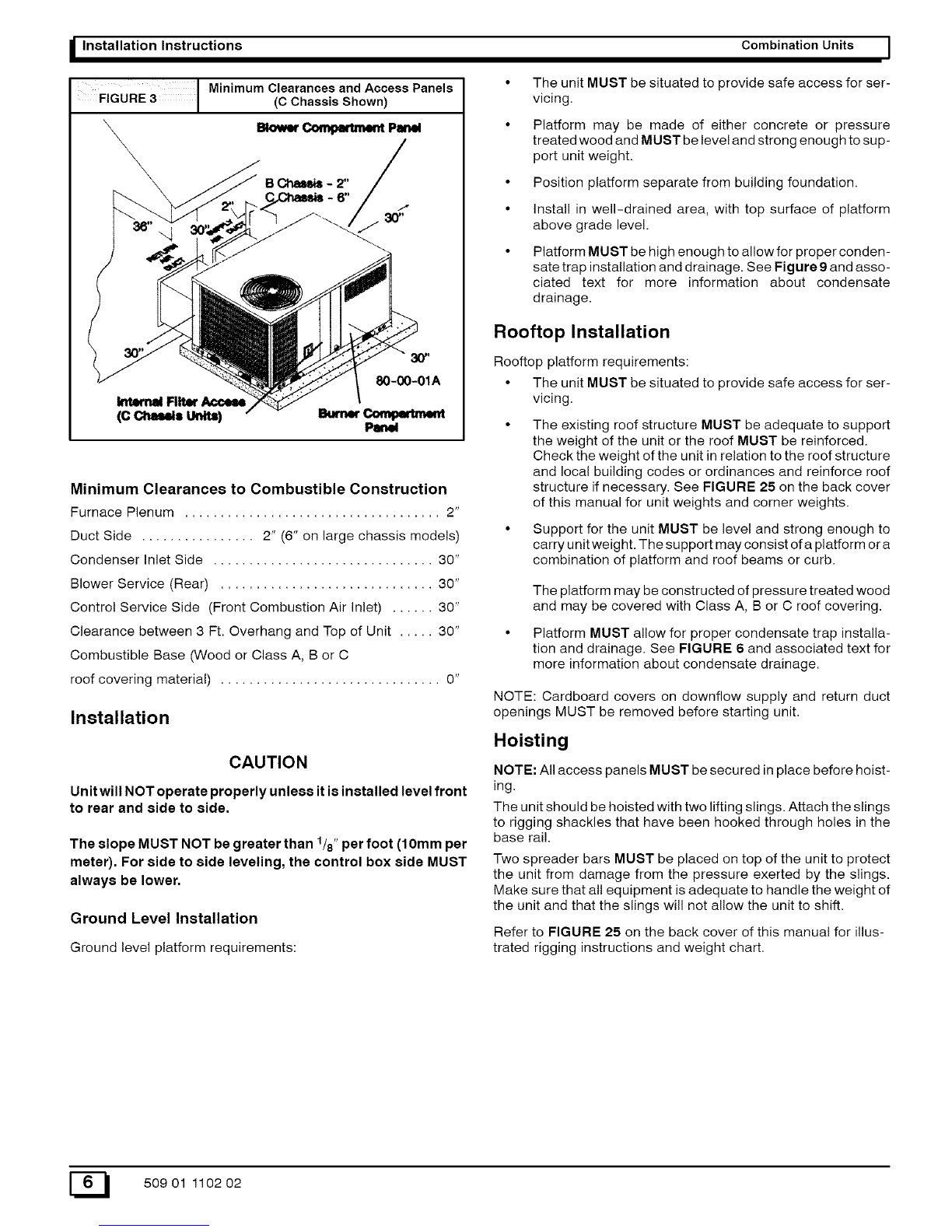
2. Safe Installation Requirements
CAUTION - Hazards or unsafe practices which COULD result in
minor personal injury or product or property damage.
Signal Words in Manuals
The signal word WARNING is used throughout this manual in the
following manner:
The signal word CAUTION is used throughout this manual in the
following manner: CAUTION
Installation or repairs made by unqualified persons can
result in hazards to you and others. Installation MUST
conform with local building codes or, in the absence of
local codes, with the ANSI Z223.1-1990 National Fuel
Gas Code and the National Electrical Code
NFPA70-1990 or in Canada the National Standard CAN/
CGA B149.1 and CSA C.22.1 -Canadian Electrical
Code Part 1.
The information contained in this manual is intended
for use by a qualified service technician familiar with
safety procedures and equipped with the proper tools
and test instruments.
Failure to carefully read and follow all instructions in
this manual can result in furnace malfunction, property
damage, personal injury and/or death.
• Installation MUST conform to the most current version of
the following standards or a superseding standard.
In the USA:
•. ANSI Z223.1-1990 National Fue! Gas Code
• National Electrical Code NFPA70-1990
In Canada:
• National Standard CAN/CGA B149.1
• CSA C.22.1 - Canadian Electrical Code Part 1.
• Do NOT use this furnace as a construction heater.
• Use only the type of gas approved for this furnace (see rat-
ing plate).
• Do NOT use open flame to test for gas leak.
• Seal supply and return air ducts.
NOTE: It is the personal responsibility and obligation of the cus-
tomer to contact aqualified installer to ensure that the installation
is adequate and conforms to governing codes and ordinances.
CAUTION
It is recommended that a qualified service technician check
the heat exchanger integrity every two (2) years, after the first
four (4) years of operation.
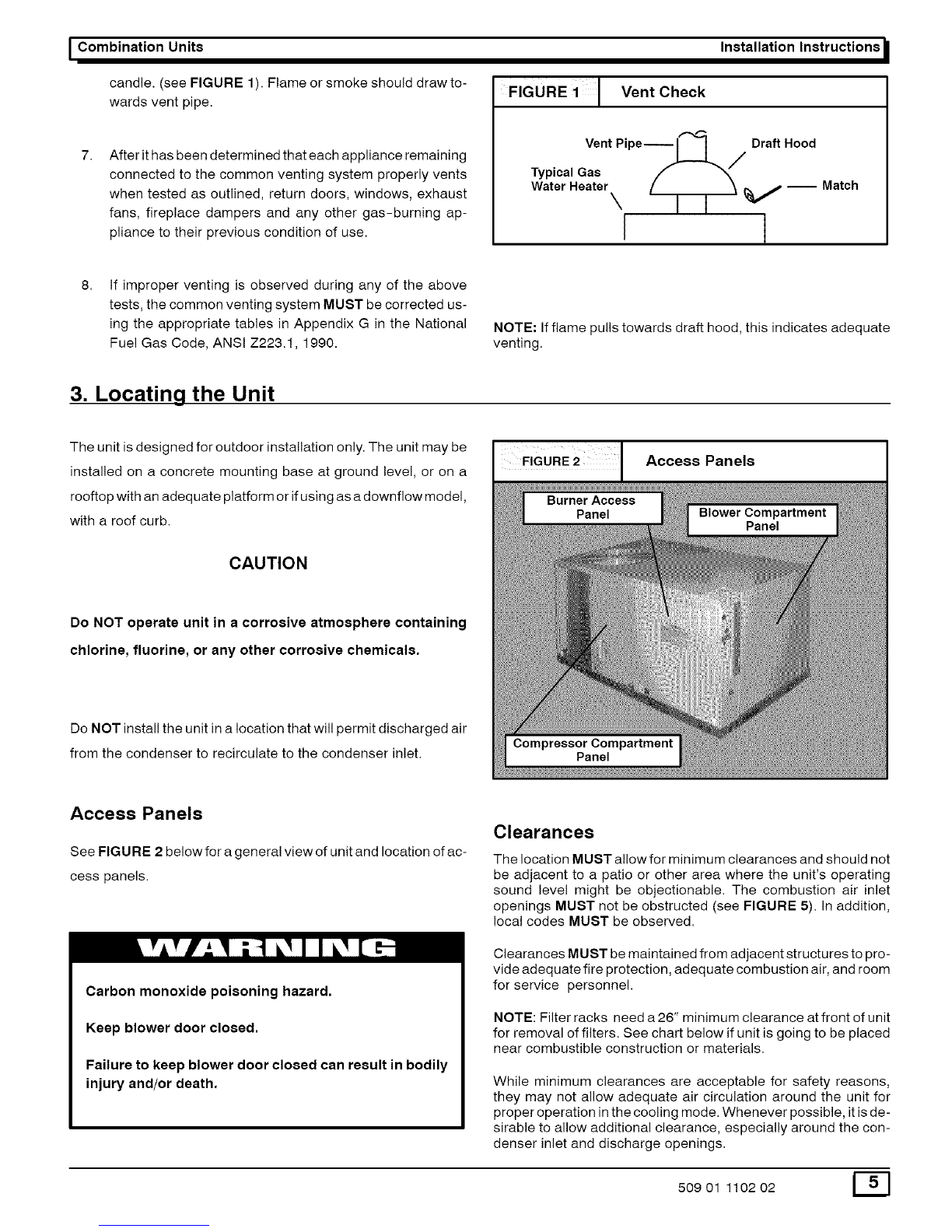
Check Pre-existing Common Vent From Old
Furnace
If the installation of the combination unit involves removing an ex-
isting furnace from a common vent with other appliances, the
venting system will probably be too large for the remaining ap-
pliances and they will not vent properly. The venting system
MUST be checked according to the following procedure.
NOTE: The following steps shall be followed with each appliance
remaining connected tothe common venting system placed in op-
eration, while the other appliances remaining connected to the
common venting system are not in operation.
1. Seal any unused openings in the common venting system.
Visually inspect the venting system for proper size and hor-
izontal pitch to ensure there is no blockage or restriction,
leakage, corrosion or other deficiencies which could cause
an unsafe condition.
insofar as is practical, close all doors and windows and all
doors between the space in which the appliances remain-
ing connected to the common venting system are located
and other spaces of the building
Turn on clothes dryers and any appliance not connected to
the common venting system. Turn on any exhaust fans,
such as range hoods and bathroom exhausts, so they will
operate at maximum speed. Do NOT operate a summer
exhaust fan. Close fireplace dampers.
Follow the lighting instructions, Place the appliance being
inspected in operation. Adjust thermostat so appliance wil!
operate continuously.
Test for spillage at the draft hood relief opening after 5 min-
utes of main burner operation. Use the flame of a match or
E_I 50901 110202


 null")