I.C.P. Srl Savannah™VG FLIGHT MANUAL Pag. 8
Issue 1/Revision 03 ICP Srl – S.P.16 km 15,150 14022 Castelnuovo Don Bosco (AT)
Jan.2012 Tel. 011.9927503 Fax 011.9927266
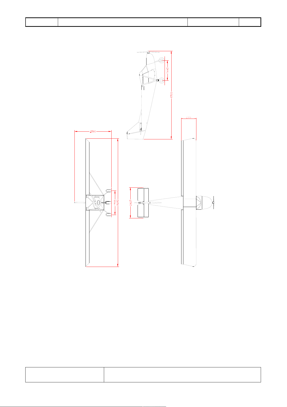
1.3 LANDING GEAR
The aircraft has a tri-cycle type landing gear. The main landing gear is made by a single-piece
aluminium alloy single-leaf leg. The nose landing gear has a telescopic, elastic chord shock absorber
and is steerable in order to ease the taxiing.
1.4 ENGINE
This aircrft has two engine installation options: the ROTAX 912 ULS/ROTAX 912 UL or
Jabiru2200. Please refer to Engine manual for any data and specifications.
WARNING: Rotax and Jabiru manufacturers issue several service and information bulletins.
It is the owner’s responsibility to acquire these documents available at www.rotax-aircraft-
engines.com or www.jabiru.net.au.
WARNING: All engines are subject to sudden stoppage. Engine stoppage can result in crash
landings, forced landings or no power landings. Such crash landings can lead to serious bodily
injury or death. Never fly the aircrafts at locations, airspeeds, altitudes, or other circumstances
from which a successful no power landing cannot be made.
These engines are not certificated aircraft engines. They have not received any safety or
durability testing and may not conform to aircraft standards.
User assumes all risks of use and fully acknowledges by his use that he knows this engine is
subject to sudden stoppage.
Note: check your country’s regulations to establish the approved condition in which the
airplane can be flown (VFR/IFR, Night/Day) and the type of airworthiness certificate that can
be issued.
1.5 ENGINE CONTROLS
There are two push-pull throttle controls with a friction adjusting knob. In the Jabiru
installation the mixture control is located near the pilot’s side throttle control. In the Rotax
installation the choke is in that position. The air-box control (Rotax 912 ULS) is located near the
throttle control: pull for hot air to carburetors, push for cold air to carburetors (for values of
temperature to maintain see chapter 2.3).
The key-operated master switch connects the electrical system to the 12V battery. The whole
electrical system is protected by thermal type re-settable breakers.
The engine can be operating with the master switch OFF and the breakers OFF since the
ignition system is independent. It can only be turned off by switching OFF the two magnetos
switches. All of the electrical instruments and devices, including the engine starter will not operate
when the master switch is OFF.
WARNING: The engine may start with the master switch OFF, if the magnetos switch (even
only one) is ON and the propeller is hand rotating or windmilling. For safety, it is strongly
recommended to pull-out the master switch key when exiting the cabin.