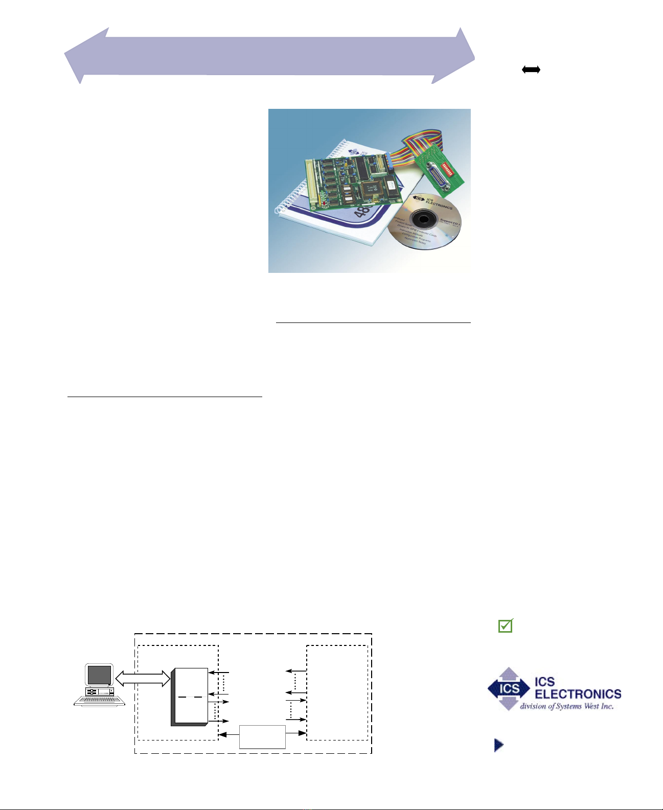
ICS ELECTRONICS 4803 User manual

7034 Commerce Circle
Pleasanton, CA 94588
Phone: 925.416.1000
Fax: 925.416.0105
Web: www.icselect.com
Description
4803
GPIB PARALLEL
DIGITAL INTERFACE
A flexible interface between
the IEEE 488 Bus and
devices with digital signals.
■ Provides a user-definable,
40-line parallel interface with
bit, byte, pulse, string and
binary data transfer capabilities.
Fully configurable to the user's
needs by bus commands.
■ Signal monitor feature allows
the 4803 to detect signal
changes on 15 inputs.
Relieves controller of time
consuming polling operation.
■ High-current drivers and input
pullup resistors.
Drives more devices, longer
lines and inputs CMOS signals
or switch contacts.
■ IEEE-488.2 compatible unit
uses SCPI commands and Short
Form commands.
Includes latest GPIB program
advances
■ Device configuration, user's
IDN message and bus address
stored in Flash.
Stored setup eliminates program
initialization statements.
■ Lock feature prevents accidental
loss or change of user
configuration.
Protects your configuration and
IDN message.
■ Interchangeable with ICS's 2303
Serial and 8003 Ethernet (LAN)
to digital boards.
Easy conversion path.
RoHS Compliant
The Model 4803 GPIB <-> Digital Inter-
face Board is an IEEE-488.2/GPIB to digital
interface with 40 I/O lines that can be used to
easily adapt devices with digital signals to the
IEEE-488/GPIB/HP-IP bus. In a typical applica-
tion, the 4803 is located inside the device and is
powered by the device's +5 volt power supply.
All signal connections can be made with plug-
in flat ribbon cables that directly connect to the
GPIB and digital headers on the 4803. When
used with the companion GPIB Connector/Ad-
dress Switch Board, the 4803 becomes a quick
and easy way to add an IEEE-488.2 interface to
most digital devices.
The 4803 includes a complete manual and
a configuration disk with sample programs. A
Starter kit is available that has everything a non-
GPIB user needs to install a 4803 in his chassis
and control it from the GPIB bus.
Versatile Digital Interface
The 4803's digital interface is configured with
commands from the GPIB Bus. The configuration
commands permit the user to designate the data
lines as inputs and/or outputs in 8-bit byte incre-
ments, connect bytes into strings, set data polarity,
data format, and handshake modes. The user
can set the output lines to his desired values and
save the current configuration in the 4803's Flash
memory. The saved configuration becomes the
new power-on configuration. At power turn-on,
the Digital I/O lines are initially tristated and then
set to the saved configuration. A Stable signal is
asserted after the digital I/O lines are configured
to enable external logic or relays.
IEEE 488/GPIB BUS INTERFACES
Data Transfer Methods
Data transfer between the computer and the
4803's digital interface can be by individual bits,
by bytes or as strings of data values to multiple
bytes as shown in Figure 2.
• Bit commands set or reset specific bits in a
byte or query a bit’s status. New pulse commands
let the user pulse single or multiple output lines
at the same time.
• Byte commands set all 8 bits in a specific
byte or read data from a byte.
• String transfer commands send strings of
data characters to one or more output bytes to
make a multi-byte output word or read a string
of data from one or more input bytes. The user
designates these bytes as inputs or outputs when
configuring the board.
In the Single Address Mode, the user can
set the 4803's configuration and transfer data as
described above. In the Dual Address Mode, the
lower address behaves like the Single Address
Mode. The upper address is used for transparent
data transfer to configured output bytes or to read
data from configured input bytes. The data is sent
or read without having
to parse any commands,
eliminating the parsing
time and speeding up
the data transfer. When
the binary data format
is used, the 4803 can
output data at rates >
50 Kbytes/sec.
4803
IEEE 488 Bus
Controller
Input
Bytes
Output
Bytes
TTL/CMOS
Input Signals or
Contact Closures
High Current
TTL Output Lines
Digital Interface
Host Chassis
Power
Supply
User's
Electronics
IEEE 488 Bus
5 V
4803 Interface Card and GPIB Connector/Ad-
dress Switch Cable Assembly
Figure 1 A typical 4803 Application

4803: APPLICATION
Reading The Input Signals
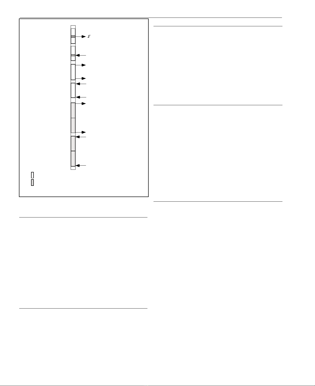
The 4803 has three ways to read the digital interface lines and
input digital data as shown in Figure 2:
• Bit queries read the status of an individual bit from a specific
byte.
• Input byte commands read 8 bits of data from a specific byte.
• Strings of data can be read from multiple bytes with a data
transfer command or inputted transparently. These bytes are
preset as string input bytes by the CONFigure command. For
input strings, the 4803 reads the configured input bytes, con-
verts the data to the selected output format, and outputs it as a
string of characters. Data can be inputted with or without hand-
shaking. The input data can be formatted as decimal numbers,
as ASCII HEX characters, or into a user selected character set.
Transparent Data Transfer
The user can input and output data without using a string com-
mand by addressing the 4803 at its upper GPIB address. Data is
read from the configured input bytes each time the 4803 is addressed
to talk. The data is input and formatted just as it would be for read-
ing strings of data.
When transparently outputting data, the 4803 converts the data
and outputs it to the configured output bytes. Data can be outputted
with or without handshaking. The 4803 automatically generates a
data strobe each time it loads all of the configured output data bytes.
Multiple data words can be transmitted in the same command by
inserting a comma between data words.
Close 1,4 or Open 1,4
Short Form Command Bytes Action
Single bit is set or reset
Read 2,3 Single input line read
Eight bits are output
Value = 0001 0011
BO3 19
Eight bits are inputted
BI4?
Four nibbles or two bytes
are outputted.
Value = 0001 0010 0011 0100
PO 1234 sent to main
(lower address)
or
1234 sent to upper addr
Four nibbles or two bytes
are input
PI? query to main
(lower GPIB address)
or
data read from upper
GPIB address
Indicates a byte whose direction is set by the first command
Indicates a byte configured as an input or output byte.
Short Form Commands are shown here for brevity but the same data transfer
occurs with the equivalent SCPI Commands.
•
•
•
•
•
•
•
•
•
•
•
•
•
•
•
•
•
•
1
2
3
4
5
6
7
8
Figure 2 4803 Digital Transfer Methods
(Figure shows 8 bytes for illustrative purposes. Actual 4803 has 5 bytes)
Input Signal Monitoring
The 4803 can monitor up to fifteen lines for signal changes and
generate an SRQ to notify the Application program when changes
occur. Monitoring is done by setting the 4803's Questionable Transi-
tion register to detect positive and/or negative signal transitions and
enabling bits in the Questionable Event register. When the enabled
bit(s) are detected, the 4803 generates an SRQ to alert the Application
to the event. The user's Application program can query the 4803's
Questionable Condition Register to determine the input signal states
and the Event Register to learn which signal changed state. Appli-
cation Bulletin 48-18 describes how to configure the 4803's Status
Reporting Structure and includes a program example.
Outputting Data
The 4803 has three ways to control the digital interface and output
data as shown in Figure 2:
• Bit commands set, reset or pulse bits in a specific byte.
• Output byte commands set all bits in a byte and latch an output
value (0 to 255) into a specific byte. Data Strobes can be manu-
ally generated if needed.
• Strings of data can be outputted to multiple bytes with a com-
mand or transferred transparently. These bytes are preset as
string output bytes by the CONFigure command. The 4803
converts the data string characters into bytes, latches the data in
the configured output bytes and generates a data strobe pulse to
update the external device. The data strings can be a series of
decimal values, ACSII HEX characters, or the 0x30-0x3F HEX
characters used in ICS's earlier interfaces.
Controlling the 4803
Figure 3 shows the 4803's configuration and data transfer com-
mands as a SCPI Command Tree. Each SCPI command has a cor-
responding Short Form command for quick programming. Most
of the functions can also be queried to verify the command setting.
(i.e. IPn? reads back the byte's polarity setting)
The ROUTe bit commands let the user set/reset and pulse indi-
vidual bits in an output byte Data Strobes can be manually generated
if needed. The PULSe commands pulse any output line as a byte,bit
value or as a channel number. A common pulse width is set by the
ROUTe:PULSe:WIDTh command. Multiple lines can be pulsed
in the same command.
SOURce Output byte commands latch an 8-bit value into a specific
output byte without pre-configuring the bytes. The SOURce string
commands let the user send strings of data to bytes that have been pre-
configured as outputs (with the CONFigure command) and generate
a data strobe with a single command. The data format is controlled
by the FORmat command. Transparent data transfer is possible in the
Dual Address Mode where bytes from the GPIB bus are formatted
and outputted to the previously configured output bytes.
SENSe bit commands read the state of a specific bit in an input
byte and SENSe byte commands read data from a specific byte.
SENSe string commands read data from bytes that have been pre-
configured as input bytes by the CONFigure command. The data
format on the GPIB bus is controlled by the FORmat command.
CALibrate Commands let the user personalize the 4803 with his
own IDN string, lock settings to prevent changes and to reset the
unit to the factory settings.

Figure 3 4803 SCPI Command Tree
4803 SCPI COMMAND TREE
SCPI Commands Short Form Cmds
SYSTem GPIB Settings
:COMM
:GPIB
:ADDRESS <numeric>
:EXT
:MODE SINGle | DUAL | SEC
:ERRor?
:VERSion?
CONFigure Configure I/O
[:DIGital]
:INPut <channel list> N
:POLarity 0 | 1 TPn
:HANDshake <boolean> TBn
:OUTput <channel list> LN
:POLarity 0 | 1 LPn
:HANDshake <boolean> LH
:CLEar 0 | 1 C
:EDR 0 | 1 E
:INHibit 0 | 1 I
:REMote 0 | 1 R
:RESet 0 | 1 X
:STRobe 0 | 1 S
:TRIGger 0 | 1 TR
:ASTATus 0 | 1 A
:BSTATus 0 | 1 B
FORmat
:TALK <ASCii | Hex | HEXL | Table>
:TRANSlation <16 char string> V
:LISTen <ASCii | Hex | HEXL | BIN | 4833>
ROUTe Bit Commands
:CLOSe byte, bit CLOSE
:OPEN byte, bit OPEN
:RESET byte BRESET
:PULSe byte,bit PL
:CHANnel number or channel list PC
:WIDTh 10-30000 [50] PW
SENSe Input Data
[:DIGital]
:DATA
[:VALue]? PI?
:PORT? number or <channel list> BI?
:PORTn? BIn?
:POLarity? Pn
:RESet:EDR ER
:BIT? 0-1 READ?
:BYTe? 0-255 BREAD?
[SOURce] Output Data
[:DIGital]
:DATA
[:VALue] 0-255 PO
:PORTn 0-255 BOn
:POLarity 0-255 OPn
:STRobe SP
CALibrate Calibrate Configuration
:IDN string (72 char max)
:DATe mm/dd/yy
:DEFault
:LOCK 1(On)| 0(Off) [0]
4803: APPLICATION
4803 Connections
The 4803 has three vertical connectors which accept flat ribbon
cable connectors. Two of the connectors contain the GPIB signals.
The 4803 only requires that one of the GPIB connectors be used to
connect it to the GPIB bus. The unused connector can be left open.
The third connector is a DIN connector with the digital I/O signals.
Figure 5 shows some of the connection possibilities.
Connector J1 is a 24-pin connector that is designed for direct
connection to a GPIB bus connector. Use a flat ribbon cable like
ICS's P/N 114439-L that has a 24-pin plug on one end and a GPIB
connector on the other end. (L is the cable length in cm) Punch a
'D' hole on the rear panel with two mounting holes. Use the metric
lock studs supplied with the cable to mount the GPIB connector on
the rear panel of the chassis.
Connector J2 is a 26-pin connector that contains the address
switch input signals as well as the GPIB bus signals. When the
external address function is enabled, the 4803 uses these signals to
set the GPIB address at power-on time. Connector J2 mates with
ICS's GPIB Connector/Address Switch Board Assemblies. The
Connector/Address Switch Assemblies are small, business card
size PC assemblies that mount a GPIB connector and an 8-bit Ad-
dress rocker switch to the rear panel of a chassis. They have a flat
ribbon cable which plugs into J2. The assemblies are available in
two layout styles. Refer to the GPIB Connector/Address Switch
data sheet for the GPIB Connector/Address Switch styles, mounting
dimensions and cable lengths.
Connector J3 is a 96-pin female DIN connector with male pins
that uses rows A and C for the 4803 digital I/O signals and power.
Mating DIN connectors have solder eyelet, wirewrap or solder pins
or use ICS's rainbow ribbon cable assembly.
Mounting Options
Standard 4803 boards have the connectors facing up on the com-
ponent side and are meant to be mounted against a panel or chassis
floor. Access the digital signals with a flat ribbon cable or wire to
the mating solder eyelet connector.
4803 boards are also available with a male DIN connector
mounted on the circuit side so the 4803 can be piggybacked on a
larger PCB assembly as shown in Figure 4. This is a good mounting
method when you already have to layout a PC board for mounting
other devices since it eliminates a cable and wiring. Use a 902257
or a 902058 female DIN connector on the PC board.
GPIB
Digital
I/O
4803
Board Outline 4.500
0.200
typ
8 plcs
0.150 dia hole
0.300 clear pad
1
1
1
PWR
TALK
BUSY
RDY
LSTN
FULL
Test LEDs
5.500
0.562 max
0.45 max 114649 Boards have female DIN on circuit side
Component Area
Figure 4 4803 Mounting Dimensions

Figure 5 4803 Connection Methods
4803: APPLICATION
4803 Relay Driver Board
The 4803DVR Board expands the 4803's
drive outputs by providing forty 300 mA relay
drivers with convenient screw terminals. A
4803 with J3 mounted on the circuit side
piggybacks on the 4803DVR board to make
a compact assembly as shown in Figure 6.
The 4803DVR board can be configured for
all 40 lines as relay driver outputs or for
less drivers and for 8 or 16 4803 TTL I/O
lines. The 4803DVR Board is powered by
the relay power supply and it supplies 5 Vdc
power to the 4803.
Refer to the separate 4803DVR Board
data sheet for complete specifications and
mounting dimensions.
GPIB Connection Cables
ICS offers two styles of the GPIB Connec-
tor/Address Switch Cable Assemblies which
connect the 4803 to a GPIB connector and
Address Switch on the rear panel. Both styles
are business card size, PC board assemblies
with a GPIB connector, metric studs and a 8
position rocker switch. The Address Switch
lets a user set the GPIB address externally
rather than saving the GPIB address in the
4803's flash memory. The two styles of the
GPIB Connector/Address Switch Cable As-
semblies are shown in Figure 7.
ICS also has a GPIB Interface Cable
Assembly that connects the 4803 to a GPIB
connector that mounts on the rear panel of the
chassis. The GPIB connector end includes
two metric studs for mounting the connector
shell to the rear panel. The flat-ribbon cable
assembly is available in any length up to 90
cm. See Figure 8.
114439-L
GPIB Connector
Cable Assy
GPIB Connector-
Address Switch
Board Assembly
P/N 113640-L or
P/N 113642-L
112343 - Open-end
Rainbow Ribbon Cable
Digital
I/O Connector (J3)
GPIB-Address Switch Header (J2) GPIB Header (J1)
Figure 6 4803 and 4803 Relay Driver Board
Starter Kit
The 4803 Starter Kit provides the OEM de-
signer with everything needed to install and test
a 4803 Board. The Starter Kit includes a 4803
Board, a GPIB Connector/Switch Board Assembly,
the open-end ribbon cable, a GPIB bus cable, a
488-LPCI or 488-USB2 GPIB Controller, ICS's
488.2V3 Drivers and software. The software
package includes a keyboard command line pro-
gram, a Visual Basic configuration program and
example programs. There is a limit of one Starter
Kit per customer.
4803 SDK Kit
The 4803SDK Kit provides everything a user
needs to write custom 4803 programs. The kit
contains the IAR 'C' language compiler, spy debug-
ger, ICS's SDK library disk, manual and spare flash
chips. ICS's library disk contains the SCPI parser
Figure 7 GPIB Connector/Address
Switch Assemblies
P/N 113642-L and P/N 113640-L
Figure 8 GPIB Interface Cable
P/N 114439-L
files, 'C' routines, make files and example
4803 files. Refer to the separate 4803SDK
data sheet for more information about the
SDK package.
Note: '-L' in the cable assembly part numbers
stands for cable length in cm from 10 to 90 cm.

4803: ORDERING GUIDE
Select from one of the two 4803 board styles and then pick your accessory items.
Part Selection Qty Part Number
Standard 4803 board with the digital IO connector on the component side (1) 4803
Select one mating digital IO connector - Solder eyelet (1) 902023
Solder pins (1) 902067
or Flat-ribbon cable (1) 902124
Select an Open end, flat ribbon cable assembly, 5 feet long (1) 112343
or
Select the 4803 Relay Driver Board (Mounts on top of std 4803) (1) 115522
Select a GPIB Connector/Address Switch Assembly - Horizontal style (1) 113640-L
Vertical style (1) 113642-L
or
Select a GPIB Flat ribbon Interface Cable with metric studs (1) 114439-L
4803 board with the digital IO connector on the circuit side (facing down)
for mounting on another PC board (1) 114648
Select digital IO connector with solder pins for the mating PC board (1) 902257 or 902058
or
Select the 4803 Relay Driver Board (Holds the 114648/114659 boards) (1) 115490
Select a GPIB Connector/Address Switch Assembly - Horizontal style (1) 113640-L
Vertical style (1) 113642-L
or
Select a GPIB Flat ribbon Interface Cable with metric studs (1) 114439-L
Notes:
1. -L is the cable length in cm. You can order any length from 10 to 90 cm.
Standard stocked lengths are: 30, 45, 60 and 90 cm. Select an appropriate length as it is best to not
have extra cable coiled up in the chassis to minimize EMI pickup. See the GPIB Connector/Address
Switch Assembly data sheet for more details.

IEEE 488 Bus Interface
The 4803's 488 Bus interface meets IEEE
STD 488.1-1987 and has the following ca-
pabilities:
SH1, AH1, T6, L4, SR1, PP0, DC1,
RL0, DT1, C0 and E2 drivers.
Address Capability
Dual primary addresses or single primary
with secondary addresses 00 and 01. Primary
address range: 0-30.
SRQ Generation
SRQs are generated if the unit is not a talker,
if SRQs are enabled and if an Enabled Event
Status Register bit or an monitored digital input
change occurs. Digital inputs monitored by the
Questionable registers.
488.2 Common Commands
*CLS, *ESE, *ESE?, *ESR?, *IDN?, *OPC,
*OPC?, *RCL, *RST, *SAV, *SRE, *SRE?,
*STB, TST? and *WAI
SCPI Commands
Used to set and query all programmable func-
tions. The 4803 conforms to SCPI 1994.0
Specification.
4803: SPECIFICATIONS
Signal Characteristics
The 4803's parallel I/O signals have the follow-
ing electrical characteristics. All time delays
listed here are maximums, all pulse widths
are minimums.
Inputs 40 Digital I/O ,
2 Status and Reset Inputs
Input High = > +2.0 V @ ±10 µA
Max High = 5.5 V
Logic Low = <0.8 V @ 250 µA
Levels with 33 Kohm pullup to +5 Vdc
for sensing contacts.
Input External Data Inhibit line
Timing SETS within 1 µs of the active edge
of the EDR Input signal and resets
after data is loaded. Data loading
time for 6 BCD/HEX characters is
0.15 ms (typ.) after the 4803 has
been addressed as a Talker
Output High = >3 V with 3 mA source
Logic High =>2 V with 24 mA source
Levels Low = 0.0 to +0.55 Vdc, 48 mA
sink
Output Data is transferred to the
Timing output 0.6 to 5.3 ms after receipt of a
terminator depending upon transfer
method.
Pulse width 10 to 30000 ms
Data Stb Output pulse width, 5 µs
Trigger Output pulse width, 5 µs
Remote Output level asserted when in the
remote state
Reset Output pulse width, 40 µs for
*RST command and true during
4803 reset time (70 ms)
Stable Output level asserted when Digital
I/O lines have been configured.
Diagnostic Indicators
Six on board LEDs with drive signals on the
DIN connector for remote LEDs
PWR, RDY, TALK, LSTN, SRQ and
ERR
Physical
Size, L x W x H
139.7 x 114.3 x 14.3 mm
(5.5 x 4.5 x 0.562 inches)
Connectors and Headers
GPIB: 24-pin 3M 2524 male conn.
GPIB/Addr: 26-pin 3M 2526 male conn.
Digital I/O: 96-pin, 3 row male DIN
conn using rows A & C.
Temperature
Operation -10° C to +70° C
Storage -20° C to +85° C
Humidity
0-90% RH without condensation
Power
+5 Vdc @ 400 mA (typical)
Included Accessories
Instruction Manual
Configuration Disk with sample programs
Available Accessories
See the Ordering Guide on page 4 for a complete
list of accessory items.
GPIB flat ribbon cable 90 cm max.,
P/N 114439-90.
GPIB Connector/Addr Sw Assy with flat
ribbon cable, 90 cm max., P/N 113640-90
or P/N 113642-90.
See the GPIB Conn/Sw data sheet.
Open-end rainbow ribbon cable, 5 ft,
P/N 112343
Mating DIN Connectors:
P/N 902023 Solder Eyelet
P/N 902067 Dip Solder
P/N 902124 Flat ribbon Cable
ORDERING INFORMATION Part Number
IEEE 488.2 to Parallel Digital Interface Board (Includes Instruction Manual and Configuration Disk) 4803
IEEE 488.2 to Parallel Digital Interface Board (Board only) 114642
4803 Starter Package with 4803, 488-LPCI card, Bus Cable, GPIB Connector/Switch Bd, and Connectors 114646-01
4803 Starter Package with 4803, 488-USB2 Controller, Bus Cable, GPIB Connector/Switch Bd, and Connectors 114646-02
4803 with connector on circuit side (Includes Instruction Manual and Configuration Disk) 114648
4803 with connector on circuit side (Board only) 114649
GPIB Connector/Address Switch Assemblies see separate data sheet
GPIB Flat Ribbon Cables see separate data sheet
Open-end Rainbow colored flat ribbon cable, 5 feet long 112343
Copyright 2010 ICS Electronics - Specifications subject to change without notice.
04/10
Table of contents
Other ICS ELECTRONICS Recording Equipment manuals