IonSense DART-Thermo LTQ User manual

DART-Thermo LTQ/Orbitrap Interface
Manual
For Thermo LTQ (Orbitrap) Velos, LTQ Orbitrap XL, LTQ
Ion Trap, Exactive High Performance, and all other
instruments that utilize the Ion Max Source
Version 20120423
IonSense Inc.
999 Broadway
Suite 404
Saugus, MA 01906

2
Thermo Ion Max—DART Interface Manual
Copyright © 2005-2010 by
IonSense Inc.
All rights reserved.
The information in this document has been carefully checked and is believed to be
reliable. However, no responsibility is assumed for inaccuracies. Statements in the
document not intended to create any warranty, expressed or implied. Specification and
performance characteristics of the hardware and software described in the manual may be
changed at any time without notice. IonSense Inc. reserves the right to make changes in
any product herein in order to improve reliability, design, or function. IonSense does not
assume any liability arising out of application or use of any product or circuit described
nor does it cover any license under its patent rights or the rights of others.
The apparatus and application of the apparatus described in this document is protected by
US Patent Number 6,949,741 and used under license; additional patents pending.
All trademarks are properties of their respective owners.

3
Thermo Ion Max—DART Interface Manual
This manual details the steps necessary to install a DART source on a Thermo LTQ Ion
Trap or Orbitrap Instrument.
Table of Contents
1. Diagram of the Thermo Source Region
2. Attaching the DART Flange to the Instrument
a. Adjusting the Exactive Side Brackets
3. Vacuum Issues
4. Optimal Parameters
4
Thermo Ion Max—DART Interface Manual
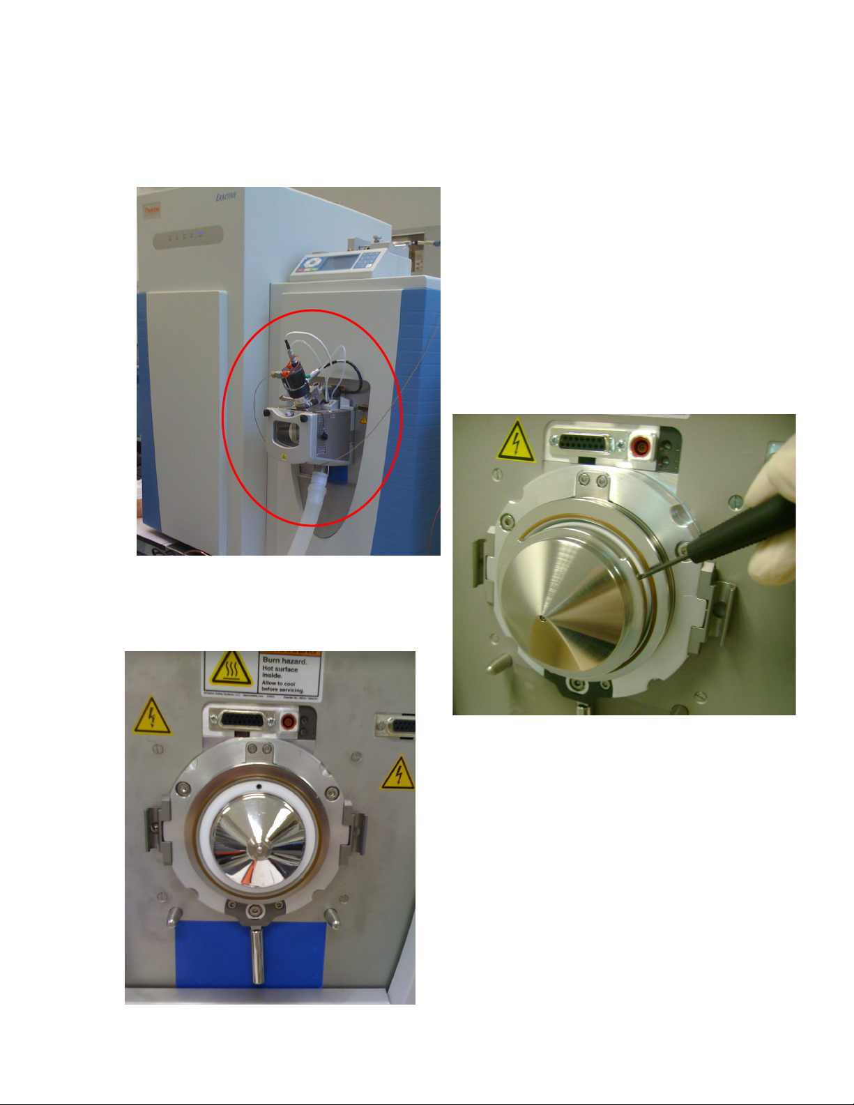
Diagram of the Thermo Source Region and Interface
Disconnect the waste hose from the
bottom of the Ion Max source, as well as
all gas, syringe, and voltage connections.
Carefully remove the Ion Max source
from the Mass Spectrometer interface
and place it aside in a safe place.
Remove the Thermo ion sweep cone as
shown in the photo above – this is the
removable spray shield that sits over the
capillary. Using a small flat-head screw
driver, loosen the set screws on the sides of
the spray shield. Caution: the shield may
be hot.
Pictured to the left is the source region with
the Thermo ion sweep cone removed.
5
Thermo Ion Max—DART Interface Manual
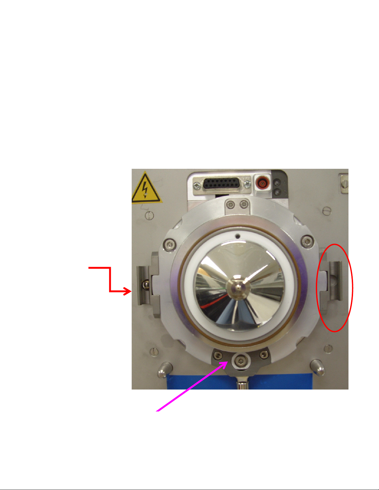
Adjusting the Side Brackets on the Thermo Exactive
Instrument
• The side brackets (circled in red in the picture below) need to be adjusted before
mounting the IonSense SI-140-GIST Vapur interface flange to an Exactive.
– The side brackets on the Exactive and LTQ need to be set 0.2 - 0.3 mm out
from the front metal surface around the API inlet.
• In general these brackets are set flush with the metal surface around the API inlet
as a default position.
• The Thermo ESI source will fit properly even with the changed positioning of the
side brackets.
• The side brackets on the
Exactive and LTQ need
to be adjusted so that
the front surface of the
brackets measures 0.2 –
0.3 mm from the front
metal surface around
the API inlet.
• The brackets are to be
moved away from the
mass spectrometer and
towards the installation
engineer.
Note: The Thermo spray shield is
also removed before mounting the
IonSense Vapur interface flange.
6
Thermo Ion Max—DART Interface Manual
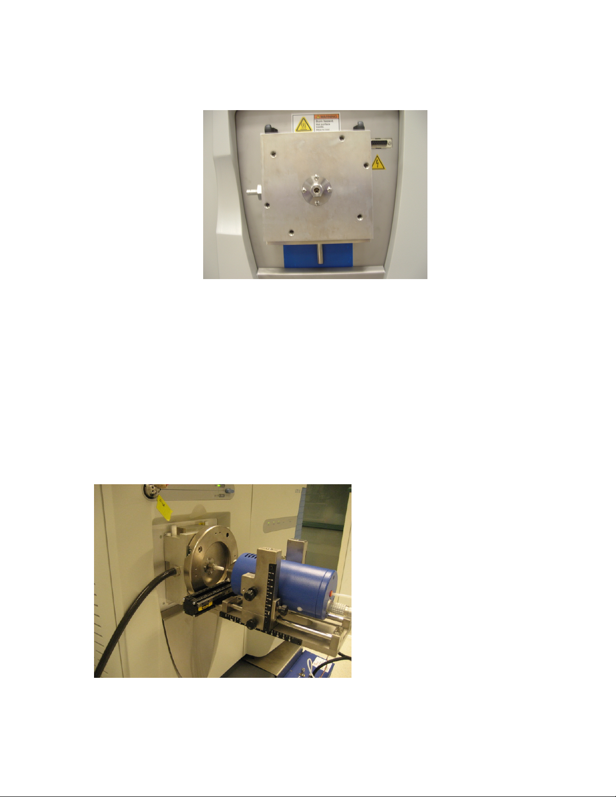
Attaching the DART Flange to the Instrument
Attach the IonSense flange to the source by matching the lock bars with the slots on the
side and then locking them on the top by turning the knobs simultaneously until they are
facing at least 45 degrees from the side plane of the flange.
Insert the ceramic tube into the Swagelok nut on the end of the VAPUR attachment and
secure it with the graphite ferrule. Take care that there is a 2mm gap inside the VAPUR
between the end of the ceramic tube and the protruding end of the Agilent capillary.
This ensures that the excess helium gas will be evacuated and maintain proper vacuum in
the instrument.
Then, attach the DART either by 1) attaching the large front ring of the DART to the
holes on the front of the flange, or 2) by screwing the base of the DART into the two
holes on the bottom of the flange.
Attach the black silicone rubber
tubing to the port on the left side
of the flange.
Finally, attach the DART source
to the flange.
Figure: The DART is shown attached to the flange using the screws in the front ring.
7
Thermo Ion Max—DART Interface Manual
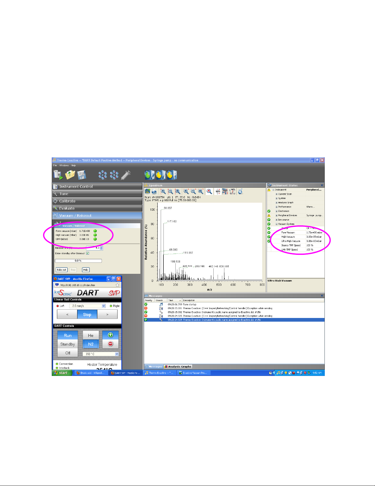
Monitoring Vacuum Levels
Use of the DART will increase the vacuum level in your instrument due to the amount of
helium being pushed into the instrument. It will not, however, harm the mass
spectrometer or cause it to function differently. Below is a printout showing what the
Thermo Exactive’s vacuum levels should be during operation. If your vacuum levels
exceed this amount, call IonSense and ask to speak with the Service Department.
Stable vacuum pressure read back values for the Exactive.
• N
2
is running through the DART source for this screen shot.
• UHV reading will rise to ~ 8-9 E-10 mbar when operating the DART with
He, but is still stable.
• The threshold where the UHV will fail is at 1.26 E-9 mbar.

8
Thermo Ion Max—DART Interface Manual
Optimal Parameters
IonSense recommends using the following operational settings:
• Scan Parameters:
• Scan Settings: 1 µ-scan by 250 ms max inject time
• AGC Target: Balanced (1e
6
)
• Inlet Parameters:
• Capillary Temp: 200° C 200° C
• Capillary Voltage: 25 V - 50 V
• Tube Lens Voltage: 120 V -120 V
• Skimmer Voltage: 26 V -25 V
• The following Source Parameters are set to zero:
• Sheath Gas Flow, Aux Gas Flow, Sweep Gas Flow.
• For all ID-CUBE experiments the Spray Voltage was set to 1 kV.
This manual suits for next models
1
Table of contents


