GS1299 FM Radio Receiver DIY Kit
3
1.4>.Wire strippers
1.5>.Philips screwdriver
2>.Please be patient until the installation is complete.
3>.The soldering iron can't touch the components for a long time(1.0 second),
otherwise it will damage the components.
4>.Pay attention to the positive and negative of the components.
5>.Strictly prohibit short circuit.
7>.User must install the LED according to the specified rules.Otherwise some LED
will not light.
8>.Install complex components preferentially.
9>.Make sure all components are in right direction and right place.
10>.It is strongly recommended to read the installation manual before starting
installation!
11>.Please wear anti-static gloves or anti-static wristbands when installing electronic
components.
8.Installation Steps(Please be patient):
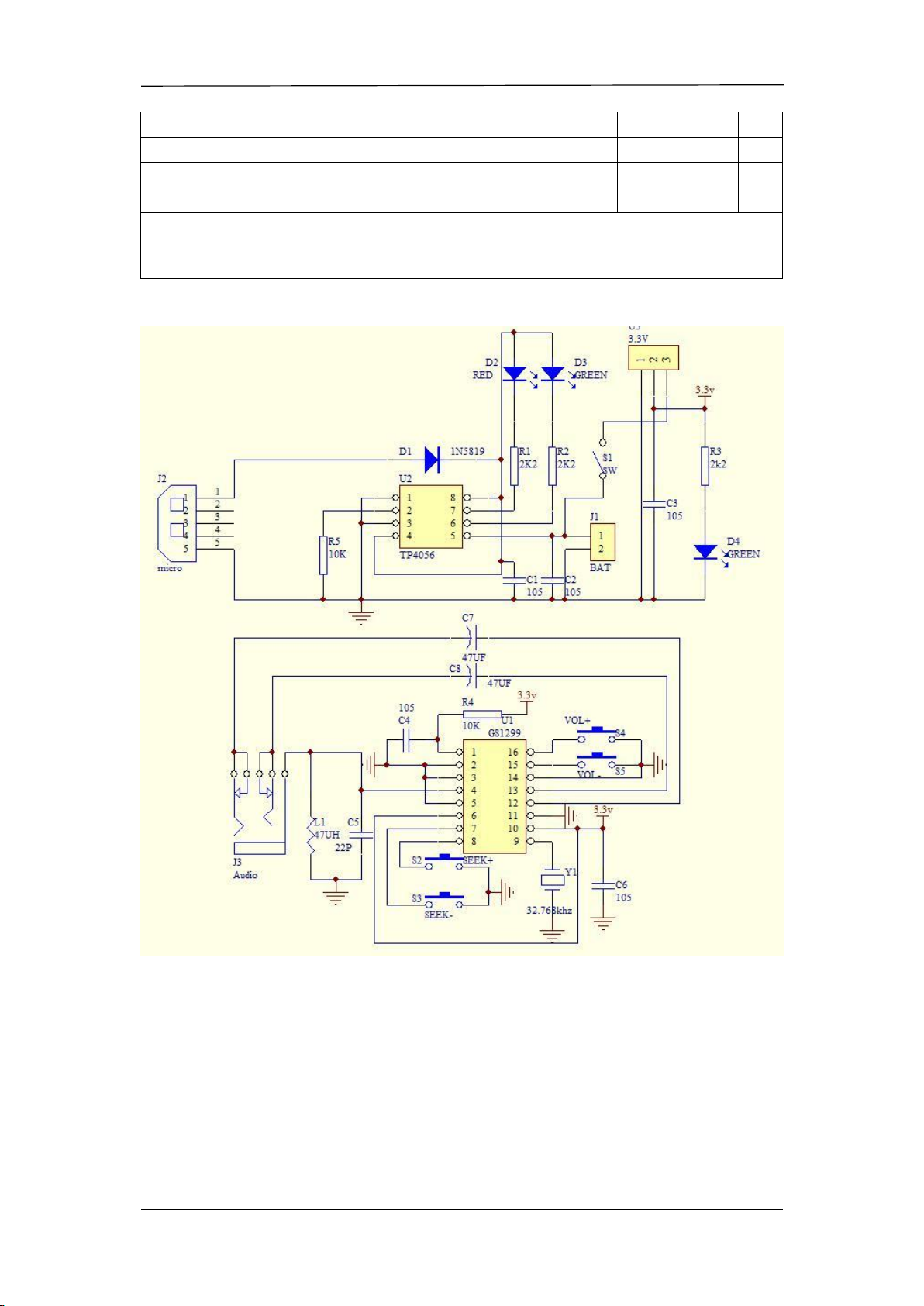
1>.Step 1: Install 1pcs SMD component SOP-16 GS1299 at U1. Verify and confirm
the installation direction of GS1299 .
2>.Step 2: Randomly choose a pad on the PCB, and then melt the solder on this pad.
3>.Step 3: Fix GS1299 : Use a soldering iron to melt tin on the pad just now and hold
GS1299 with tweezers in the other hand to place/press on U1 to prevent movement. Take
care to match and align each pads. Then remove soldering iron. Then remove tweezers
after solder tin cooling and solidification.
4>.Step 4: Connect others pads on GS1299 to pads on PCB by tin and soldering iron.
5>.Step 5: Install 1pcs SOP-8 TP4056 Lithium battery charging IC at U2 by the same
method.
6>.Step 6: Install 1pcs 32.768KHz Crystal oscillator at Y1.Note: Bend the pins before
installing.
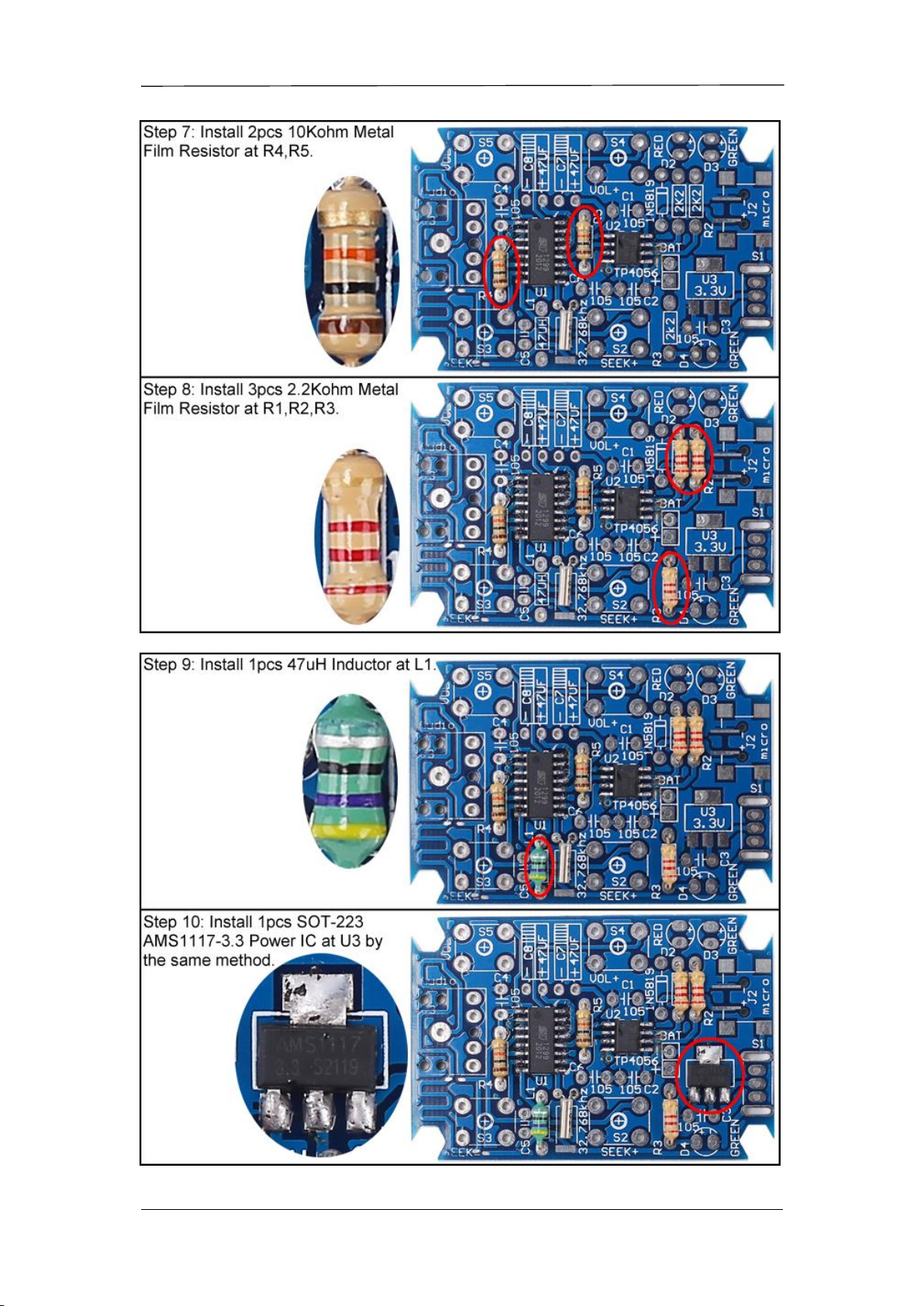
7>.Step 7: Install 2pcs 10Kohm Metal Film Resistor at R4,R5.
8>.Step 8: Install 3pcs 2.2Kohm Metal Film Resistor at R1,R2,R3.
9>.Step 9: Install 1pcs 47uH Inductor at L1.
10>.Step 10: Install 1pcs SOT-223 AMS1117-3.3 Power IC at U3 by the same
method.
11>.Step 11: Install 1pcs DO-41 1N5819 diode at D1.Pay attention to the installation
direction. Note: The white mark on Diode and the white mark on PCB are corresponding.
12>.Step 12: Install 1pcs USB Micro Socket Switch at J2.
13>.Step 13: Install 1pcs 22pF Ceramic Capacitor at C5.
14>.Step 14: Install 5pcs 0.1uF 104 Monolithic Capacitor at C1,C2,C3,C4,C6.
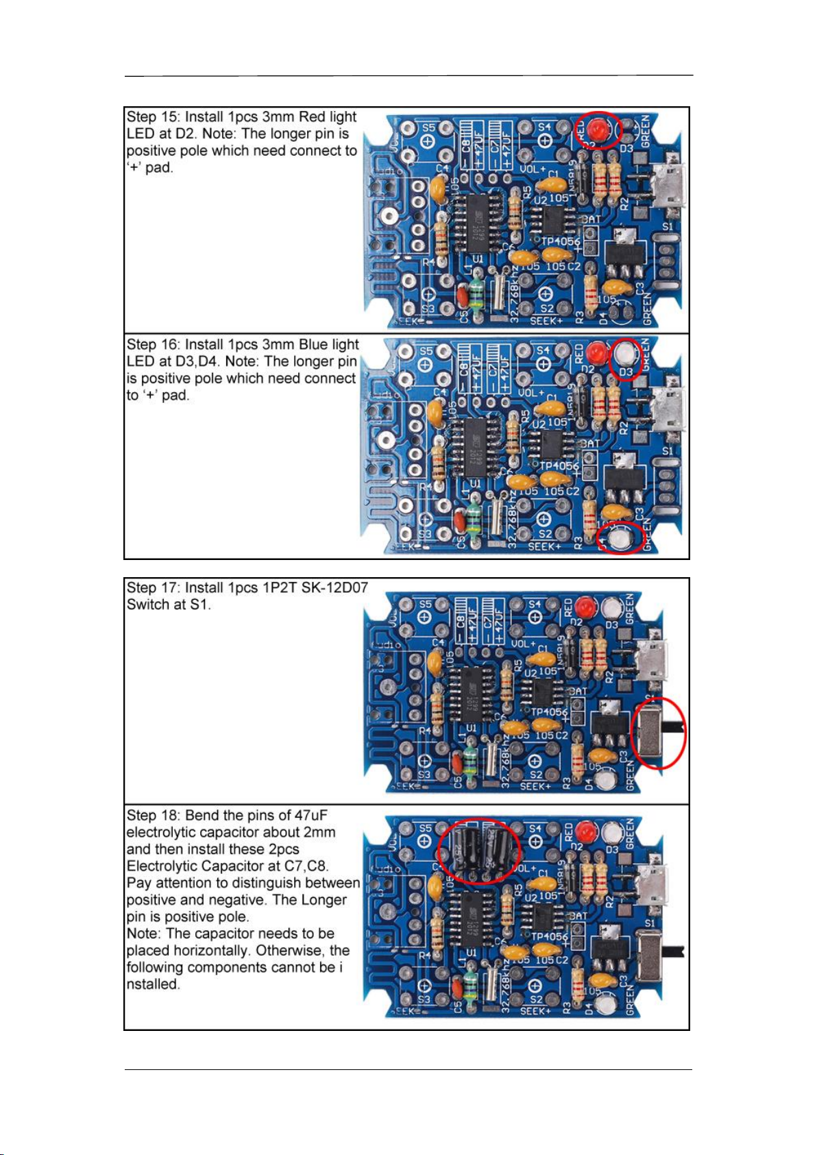
15>.Step 15: Install 1pcs 3mm Red light LED at D2. Note: The longer pin is positive
pole which need connect to ‘+’ pad.
16>.Step 16: Install 1pcs 3mm Blue light LED at D3,D4. Note: The longer pin is
positive pole which need connect to ‘+’ pad.
17>.Step 17: Install 1pcs 1P2T SK-12D07 Switch at S1.
18>.Step 18: Bend the pins of 47uF electrolytic capacitor about 2mm and then install
these 2pcs Electrolytic Capacitor at C7,C8. Pay attention to distinguish between positive
and negative. The Longer pin is positive pole. Note: The capacitor needs to be placed
horizontally. Otherwise, the following components cannot be installed.