ICStation GY21106-1 User manual

1
https://www.icstation.com/
RDA5807 87MHz-108MHz FM Radio Receiver DIY Kit
1.Introduction:
It is a 3.0V RDA5807 87MHz-108MHz FM Radio Receiver DIY Kit. It is a simple FM
receiver and can be used all over the world with power by AA*2 battery. It is very suitable
for users to learn electronic circuits, practice and proficient soldering skills, enhance
electronic professional knowledge and interest.
2.Feature:
1>.Universal frequency 87MHz-108MHz
2>.Stable fixing bracket
3>.Support battery charging function
3.Parameter:
1>.Product Name:RDA5807 FM Radio Receiver DIY Kit
2>.Work Voltage:DC 3.0V
3>.Power Type:AA*2 Battery (Not Included)
4>.Channel: Dual channel
5>.FM Frequency: 87MHz-108MHz
6>.Frequency accuracy:0.1MHz
7>.Equivalent noise:>=30dB
8>.Work Temperature:-25℃~85℃
9>.Work Humidity:5%~95%RH

2
10>.Size(Installed):123x95x56mm
4.Function:
1>.Buttons VOL- and VOL+ are used to adjust volume.
2>.Buttons FM- and FM+ are used to switch FM stations.
3>.The toggle switch on the side is the power switch.
5.Component Listing:
NO.
Component Name
PCB Marker
Parameter
QTY
1
Metal Film Resistor
R7,R8
1Kohm
2
2
Metal Film Resistor
R3,R4
4.7ohm
2
3
Metal Film Resistor
R6
10ohm
1
4
Metal Film Resistor
R5,R9
0ohm
2
5
Metal Film Resistor
R1,R2
240ohm
2
6
Indutor
L1
100uH
1
7
Monolithic Capacitor
C4,C5
4.7uF 475
2
8
Monolithic Capacitor
C3
0.22uF 224
1
9
Monolithic Capacitor
C10,C11
0.1uF 104
2
10
Ceramic Capacitor
C2
22pF
1
11
Ceramic Capacitor
C1
100pF
1
12
Electrolytic Capacitor
C6,C7
100uF
2
13
Electrolytic Capacitor
C8,C9
220uF
2
14
Electrolytic Capacitor
C12
470uF
1
15
Crystal Oscillator
Y1
32768Hz
1
16
3mm Red LED
LED1,LED2
2
17
0.5W Speaker
LS1,LS2
2
18
Toggle Switch
S6
1P2T
1
19
Black Button
S1-S5
6*6*8mm
5
20
RDA5807 FM Receiver
U1
SOP-16
1
21
TDA2822 Amplifier
U2
DIP-8
1
22
IC Socket
U2
DIP-8
1
23
AA*2 Battery Box
BT
1
24
FM Antenna
J1
1
25
M2*10mm Screw
6
26
M2 Nut
6
27
Wire
10cm
1
28
Main PCB
123*82*1.6mm
1
29
PCB Bracket
56*21*1.6mm
2
Note:Users can complete the installation according to the PCB silk screen and
component list.
6.Schematic diagram:

3
7.Installation Tips:
1>.User needs to prepare the soldering tool at first:
1.1>.Small screwdriver
1.2>.Small wire cutters
1.3>.Fine tip soldering iron(Recommend using a fine point soldering tip)
1.4>.Good quality small gauge solder(recommend no larger than 1.0 mm)
1.5>.Magnifying glass
2>.Please be patient until the installation is complete.
3>.The soldering iron can't touch the components for a long time(1.0 second),
otherwise it will damage the components.
4>.It is recommend building the project starting with the lowest components first and
working up to the highest components. This is a common practice as it makes it easier to
hold the low components on the board while soldering
5>.Pay attention to the positive and negative of the components.
6>.Strictly prohibit short circuit.
7>.User must install the LED according to the specified rules.Otherwise some LED will
not light.
8>.Install complex components preferentially.
9>.Make sure all components are in right direction and right place.
10>.Check that all of the LED can be illuminated.
11>.Please wear anti-static gloves or anti-static wristbands when installing electronic
components.
9.Installation Steps(Please be patient ):
1>.Step 1: Install 1pcs SMD components SOP-16 RDA5807 FM Receiver at U1. Verify
and confirm the installation direction of RDA5807. The rectangular silk screen on the PCB
coincides with the crystal oscillator on the RDA5807 to locate the installation direction.
2>.Step 2: Randomly choose a pad on the PCB, and then melt the solder on this pad.

4
3>.Step 3: Fix RDA5807: Use a soldering iron to melt tin on the pad just now and hold
RDA5807 with tweezers in the other hand to place/press on U1 to prevent movement.
Take care to match and align each pads. Then remove soldering iron. Then remove
tweezers after solder tin cooling and solidification.
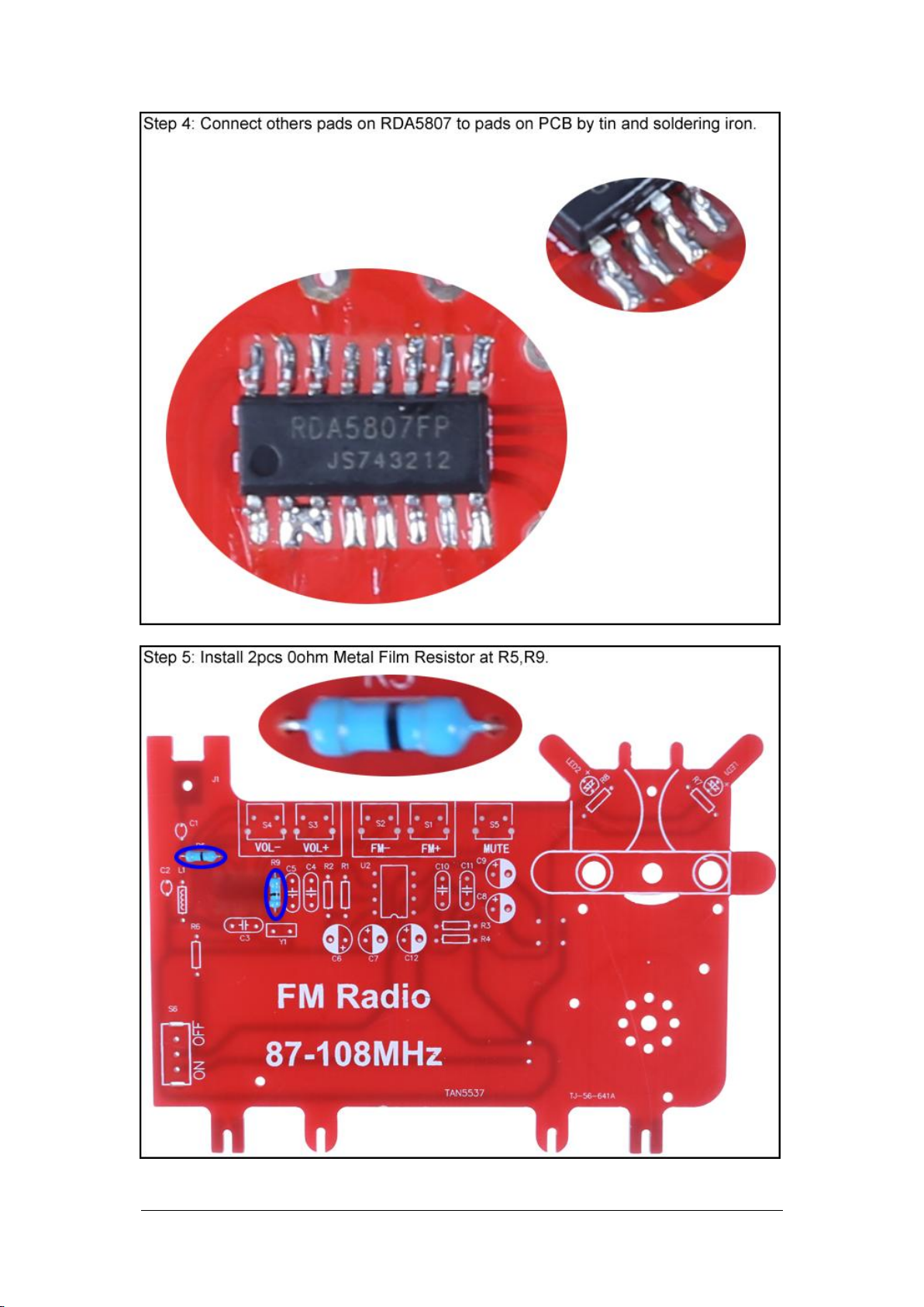
4>.Step 4: Connect others pads on RDA5807 to pads on PCB by tin and soldering iron.
5>.Step 5: Install 2pcs 0ohm Metal Film Resistor at R5,R9.
6>.Step 6: Install 2pcs 4.7ohm Metal Film Resistor at R3,R4.
7>.Step 7: Install 1pcs 10ohm Metal Film Resistor at R6.
8>.Step 8: Install 2pcs 240ohm Metal Film Resistor at R1,R2.
9>.Step 9: Install 2pcs 1Kohm Metal Film Resistor at R7,R8.
10>.Step 10: Install 1pcs 100uH Inductor at L1.
11>.Step 11: Install 1pcs DIP-8 IC Socket at U2.There is a mark(notch) on one end of
the IC Socket and there is a mark(curved silk screen printing) on PCB where the IC
Socket can place on.These two marks are corresponding to each other and are used to
specify the installation direction of the IC Socket.
12>.Step 12: Install 1pcs 22pF Ceramic Capacitor at C2.
13>.Step 13: Install 1pcs 100pF Ceramic Capacitor at C1.
14>.Step 14: Install 1pcs 0.22uF 224 Monolithic Capacitor at C3.
15>.Step 15: Install 2pcs 0.1uF 104 Monolithic Capacitor at C10,C11.
16>.Step 16: Install 2pcs 4.7uF 475 Monolithic Capacitor at C4,C5.
17>.Step 17: Install 2pcs 3mm Red LED at LED1,LED2. Pay attention to the installation
direction. The shorter pin is negative pole.
18>.Step 18: Install 1pcs 1P2T Toggle Switch at S6.
19>.Step 19: Install 2pcs 220uF Electrolytic Capacitor at C8,C9. Pay attention to
distinguish between positive and negative.The shorter pin is negative pole.
20>.Step 20: Install 2pcs 100uF Electrolytic Capacitor at C6,C7. Pay attention to
distinguish between positive and negative.The shorter pin is negative pole.
21>.Step 21: Install 1pcs 470uF Electrolytic Capacitor at C12. Pay attention to
distinguish between positive and negative.The shorter pin is negative pole.
22>.Step 22: Install 1pcs 32.768KHz Crystal Oscillator at Y1.
23>.Step 23: Install 5pcs 6*6*8mm Black Button at S1-S5.
24>.Step 24: Install 1pcs DIP-8 IC TDA2822 Amplifier at U2. There is a mark(notch) on
one end of the IC Socket and there is a mark(curved silk screen printing) on PCB where
the IC can place on. These two marks are corresponding to each other and are used to
specify the installation direction of the IC.
25>.Step 25: Fix 2pcs 0.5W Speaker on another side by 6pcs M2*10mm Screw and
6pcs M2 Nut.
26>.Step 26: Connect speaker to PCB by yellow wires which can cut from 10cm wire.
27>.Step 27: Fix AA*2 battery box by its back glue and red connect to pad ‘ + ’.
28>.Step 28: Install 1pcs 75ohm Antenna at J1. Keep a distance more than 5mm from
PCB and fix by tin(not screw). Note that the antenna should be installed on the back of
PCB.
29>.Step 29: Fix 2pcs PCB Bracket.Note that the pads must be aligned.
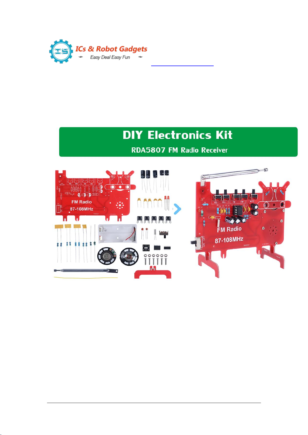
10.Install shown steps:

5

6

7

8

9

10

11

12

13

14

15

16

17

18

19

20
11.SMD IC Installation Method:
1>.Step 1: Melt a small amount of solder on the pad which IC can placed(It is used for
positioning the chip in the next step).
2>.Step 2: Hold the chip with tweezers and adjust the position so that the pins of the
chip coincide with all the pads and are close to the pads.Pay attention to the mounting
direction of the chip.
3>.Step 3: Use a soldering iron to melt the solder just now so that the chip can be
fixed.At this time, the tweezers are still holding the chip and keep calibrating the position.
4>.Step 4: Melt a lot of solder on top of another row of chip pins.Make sure there is
enough solder between each pin and the pad.
5>.Step 5: Using a solder sucker to suck out excess solder. While heating with a
soldering iron, suck out excess solder. Tips: First find a suitable place to place the tin
remover, and then use a soldering iron to melt the solder.
6>.Step 6: Check whether enough pads are filled between each pin and pad.
Otherwise, you need to add more solder.
7>.Step 7: In the same way, install another row of pins.
8>.Note:This is an installation method of the SMD chip, and user can also use other
installation methods.
Other ICStation Toy manuals
Popular Toy manuals by other brands

Mega Bloks
Mega Bloks Barbie 80247 manual

V-tech
V-tech V.Smile Baby Backyardigans Big Backyard... user manual

WATT AGE
WATT AGE Thermalaire EP RTF instruction manual

KNEX
KNEX 17009 manual

Badger Basket
Badger Basket 10.0/0714/TG Assembly and use instructions

Mattel
Mattel Girl tech Sugar Cubes instruction manual