manuals.online logo
Brands
  1. Home
  2. •
  3. Brands
  4. •
  5. iDataLink
  6. •
  7. Receiver
  8. •
  9. iDataLink maestro Rr User manual

iDataLink maestro Rr User manual

Other manuals for maestro Rr

48

Popular Receiver manuals by other brands

Televes ZAS HD SAT user manual

Televes

Televes ZAS HD SAT user manual

Realistic DX-75 Operating and service instructions

Realistic

Realistic DX-75 Operating and service instructions

Saris 4620 Assembly instructions

Saris

Saris 4620 Assembly instructions

Mini DTR 206C PVR user manual

Mini

Mini DTR 206C PVR user manual

RF Elements TwistPort manual

RF Elements

RF Elements TwistPort manual

Denon DN-200WS user guide

Denon

Denon DN-200WS user guide

Yamaha RX-V467 owner's manual

Yamaha

Yamaha RX-V467 owner's manual

Russound SaphIR 858 instruction manual

Russound

Russound SaphIR 858 instruction manual

Quasonix RDMS Firmware update procedure

Quasonix

Quasonix RDMS Firmware update procedure

Pioneer XV-HTD1 Service manual

Pioneer

Pioneer XV-HTD1 Service manual

ATZ HDMI-V2-44HE150 manual

ATZ

ATZ HDMI-V2-44HE150 manual

Sony XNV-770BT MyTomTom Specifications

Sony

Sony XNV-770BT MyTomTom Specifications

Grundig STR 7122 TWIN Service manual

Grundig

Grundig STR 7122 TWIN Service manual

Creative Blaster Modem user guide

Creative

Creative Blaster Modem user guide

Panduit ATLONA AT-OME-RX11 installation guide

Panduit

Panduit ATLONA AT-OME-RX11 installation guide

VOLTCRAFT UTPS-40 operating instructions

VOLTCRAFT

VOLTCRAFT UTPS-40 operating instructions

JVC KW-ADV794 instructions

JVC

JVC KW-ADV794 instructions

Litelink VT-1001 operating instructions

Litelink

Litelink VT-1001 operating instructions

manuals.online logo
manuals.online logoBrands
  • About & Mission
  • Contact us
  • Privacy Policy
  • Terms and Conditions

Copyright 2025 Manuals.Online. All Rights Reserved.

NOTICE: Automotive Data Solutions Inc. (ADS) recommends having this installation performed by a certified technician. Logos and trademarks used here in
are the properties of their respective owners.
WARNING
Pressing the printer icon or “quick printing” this document will print
all of the guides in this compilation.
Open the Bookmarks menu and find your vehicle OR scroll
down until you find the install guide for your vehicle.
Print only the pages for your vehicle using the advanced
options in the Print menu.
Install your Maestro RR according to the guide for your vehicle.
HOW TO USE THIS INSTALL GUIDE
1
2
3
SELECT VEHICLE
PRINT PAGES NEEDED
2012-2014
Ford Focus
with 4.3" MyFord screen
INSTALL GUIDE
RETAINS STEERING WHEEL CONTROLS, VEHICLE SETTINGS, AND MORE!
NOTICE: Automotive Data Solutions Inc. (ADS) recommends having this installation performed by a certified technician. Logos and trademarks used here
in are the properties of their respective owners.
PRODUCTS REQUIRED
iDatalink Maestro RR or RR2 Radio Replacement Interface
iDatalink Maestro FOC1 Dash Kit
PROGRAMMED FIRMWARE
ADS-RR(SR)-FOR02-AS
ADDITIONAL RESOURCES
Maestro RR2 Programmable Outputs Guide
OR
OPTIONAL ACCESSORIES
ADS-RR(SR)-FOC1-AS-IG-EN maestro.idatalink.com
Ford Focus with 4.3" MyFord screen 2012-2014
Automotive Data Solutions Inc. © 2019 2
WELCOME
NEED HELP?
Congratulations on the purchase
of your iDatalink Maestro RR Radio
replacement solution. You are
now a few simple steps away from
enjoying your new car radio with
enhanced features.
Before starting your installation,
please ensure that your iDatalink
Maestro module is programmed
with the correct firmware for your
vehicle and that you carefully review
the install guide.
Please note that Maestro RR will
only retain functionalities that
were originally available in the
vehicle.
TABLE OF CONTENTS
Installation Instructions 3
Wiring Diagram 6
Troubleshooting Table 7
1 866 427-2999
maestro.idatalink.com/support
www.12voltdata.com/forum
[email protected]
ADS-RR(SR)-FOC1-AS-IG-EN maestro.idatalink.com
Ford Focus with 4.3" MyFord screen 2012-2014
Automotive Data Solutions Inc. © 2019 3
Fig. 1.3
Fig. 1.5
Fig. 1.4
Fig. 1.6
Fig. 1.1 Fig. 1.2
INSTALLATION INSTRUCTIONS
DASH DISASSEMBLY
1. Pry off center cap at the bottom of the factory radio bezel to
expose two (2) screws. (Fig. 1.1)
2. Remove two (2) Torx T25 screws. (Fig. 1.2)
3. Starting at the bottom, pull the bezel forward. At the same
time, use a panel removal tool to pry the bezel. (Fig. 1.3)
Disconnect the connector at the back of the bezel and put it
to the side.
4. Remove four (4) Torx T25 screws holding the screen frame,
and two (2) Torx T25 holding the radio body. (Fig. 1.4)
5. Remove both the screen assembly and the radio body,
disconnecting the plugs in the process. (Fig. 1.5)
6. Remove the vents from the factory bezel. (Fig. 1.6)
1
ADS-RR(SR)-FOC1-AS-IG-EN maestro.idatalink.com
Ford Focus with 4.3" MyFord screen 2012-2014
Automotive Data Solutions Inc. © 2019 4
Fig. 2.2
Fig. 2.4Fig. 2.3
Fig. 2.1
Fig. 3.2Fig. 3.1
Fig. 2.5
INSTALLATION INSTRUCTIONS
1
DASH KIT ASSEMBLY
1. Attach the pocket of the FOC1 to the bezel using the four (4)
provided screws. (Fig. 2.1)
NOTE: If the pocket sticks when opening or closing, you
can adjust the fit by loosening the screws that secure the
pocket by 1/4 turn until the pocket no longer sticks.
2. Install the combination hazard/lock switch into the FOC1
bezel (the other hazard switch is not used). (Fig. 2.2)
NOTE: If the hazard button squeaks when you press it, pop
the hazard switch out of the kit and then re-install it. This
should eliminate the noise.
3. Install the factory vents on the FOC1 kit. (Fig. 2.3)
4. Using the screws provided, attach to the FO1C, the bottom
bezel trim that matches the factory bezel. (There are two
trim pieces that come with the kit, make sure to attach the
style that matches the shape of the underside of the OEM
bezel.) (Fig. 2.4)
5. Install the metal brackets on to the aftermarket radio. (Fig.
2.5)
ADS-RR(SR)-FOC1-AS-IG-EN maestro.idatalink.com
Ford Focus with 4.3" MyFord screen 2012-2014
Automotive Data Solutions Inc. © 2019 5
Fig. 2.2
Fig. 2.4Fig. 2.3
Fig. 2.1
Fig. 3.2Fig. 3.1
INSTALLATION INSTRUCTIONS
MAKE CONNECTIONS (refer to wiring diagram)
1. Locate the aftermarket radio’s main harness. Cut the
WHITE, GRAY, GREEN and PURPLE RCA tips. Connect the
wires from the aftermarket radio’s main harness to the
FOC1 t-harness and match the wire functions (refer to
diagram).
2. Connect the FOC1 T-harness to the factory radio harness.
Plug the backup camera cable into the factory harness (if
applicable).
3. Plug the OBD2 connector into the OBD2 port of the vehicle,
located under the driver side dash, and run the wires up to
the radio cavity.
4. Connect all harnesses to the Maestro RR module.
5. Plug the aftermarket radio harnesses into the aftermarket
radio. Plug the Steering Wheel Control Cable into the
aftermarket radio. Plug the backup camera RCA into the
aftermarket radio (if applicable).
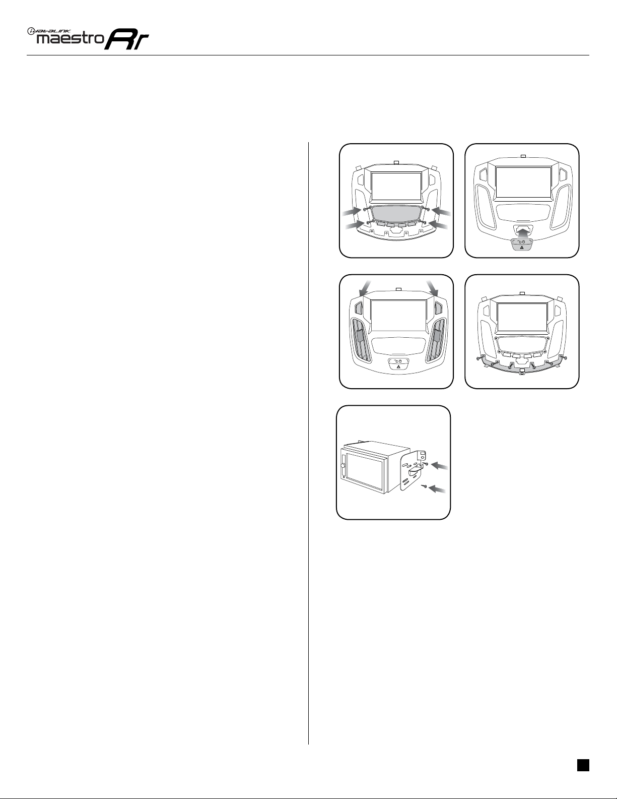
6. Insert the radio into the dash and secure the metal
brackets with (4) T25 screws. (Fig. 3.1)
7. Connect all the harnesses to the FOC1 kit, and secure it
in the dash. Test your installation before completely re-
assembling the bezel to the vehicle. (Fig. 3.2)
1
ADS-RR(SR)-FOC1-AS-IG-EN maestro.idatalink.com
Ford Focus with 4.3" MyFord screen 2012-2014
Automotive Data Solutions Inc. © 2019 6
1
BACKUP CAMBACKUP CAM
WHITE - LF SPEAKER (+)
WHITE/BLACK - LF SPEAKER (-)
GRAY - RF SPEAKER (+)
GRAY/BLACK - RF SPEAKER (-)
GREEN - LR SPEAKER (+)
GREEN/BLACK - LR SPEAKER (-)
PURPLE/BLACK - RR SPEAKER (-)
PURPLE - RR SPEAKER (+)
CUT AND REMOVE
THE RCA CONNECTORS
YELLOW - 12V (+)
BLACK - GROUND
RED - ACCESSORY (+)
ORANGE - ILLUMINATION (+)
PURPLE/WHITE - REVERSE LIGHT (+)
LTGREEN - E-BRAKE (-)
BLUE/WHITE - AMP. TURN ON (+)
PINK - VEHICLE SPEED
YELLOW/BLACK - FOOT BRAKE
BROWN (NOT CONNECTED)
WIRES FROM
VEHICLE
MAIN
HARNESS
HARNESS BEHIND RADIO
RCA CABLE
FACTORY RADIO HARNESS
RR-FOC1 T-HARNESS
WIRING DIAGRAM
STEP 2
STEP 5
STEP 4
STEP 7
STEP 1
MAESTRO RR MODULE
STEP 3 OBDII CONNECTOR
BLUE - POWER ANTENNA
BLUE
N.C.
WHITE
CONNECT TO
AFTERMARKET RADIO
STEERING WHEEL
CONTROL CABLE
SEE
AFTERMARKET
RADIO GUIDE
FOR WIRE
COLORS
AUDIO
CABLE
DATA
CABLE
NOT REQUIRED
ADS-RR(SR)-FOC1-AS-IG-EN maestro.idatalink.com
Ford Focus with 4.3" MyFord screen 2012-2014
Automotive Data Solutions Inc. © 2019 7
TROUBLESHOOTING TABLE
PROBLEM SOLUTION
There is no image from the backup camera and/or the steering wheel
controls do not work.
Ensure the 12-pin connector from the 4.3” factory screen is plugged into the
12 pin plug of the FOC1 t-harness.
The light on the Maestro is flashing RED ONCE. There is no firmware on the module; flash the RR module.
When a button on the steering wheel is pressed, the light on the Maestro
module blinks but the radio does not respond.
Ensure the blue 4-pin steering wheel control cable is connected between the
maestro and the radio (the radio will use either the 3.5mm jack or the Blue/
Yellow wire, not both).
Refer to radio’s owners manual to verifie if the radio has this function:
Steering Wheel Control (ON/OFF) : choose ON.
or
Steering Wheel Control (Custom/Preset): choose Preset
MAESTRO RR RESET PROCEDURE:
Turn the key to the OFF position, then disconnect all connectors from the module.
Press and hold the module’s programming button and connect all the connectors back to the module. Wait, the module’s LED will flash RED rapidly (this may
take up to 10 seconds).
Release the programming button. Wait, the LED will turn solid GREEN for 2 seconds to show the reset was successful.
TECHNICAL ASSISTANCE
Phone: 1-866-427-2999
Email: maestr[email protected]
Web: maestro.idatalink.com/support add www.12voltdata.com/forum/
IMPORTANT: To ensure proper operation, the aftermarket radio needs to have the latest firmware from the manufacturer. Please visit the radio
manufacturer’s website and look for any updates pertaining to your radio.
2015-2018
Ford Focus
with 4.3" MyFord screen
INSTALL GUIDE
RETAINS STEERING WHEEL CONTROLS, VEHICLE SETTINGS, AND MORE!
NOTICE: Automotive Data Solutions Inc. (ADS) recommends having this installation performed by a certified technician. Logos and trademarks used here
in are the properties of their respective owners.
PRODUCTS REQUIRED
iDatalink Maestro RR or RR2 Radio Replacement Interface
iDatalink Maestro FOC1 Dash Kit
PROGRAMMED FIRMWARE
ADS-RR(SR)-FOR02-AS
ADDITIONAL RESOURCES
Maestro RR2 Programmable Outputs Guide
OR
OPTIONAL ACCESSORIES
ADS-RR(SR)-FOC1-AS-IG-EN maestro.idatalink.com
Ford Focus with 4.3" MyFord screen 2015-2018
Automotive Data Solutions Inc. © 2019 2
WELCOME
NEED HELP?
Congratulations on the purchase
of your iDatalink Maestro RR Radio
replacement solution. You are
now a few simple steps away from
enjoying your new car radio with
enhanced features.
Before starting your installation,
please ensure that your iDatalink
Maestro module is programmed
with the correct firmware for your
vehicle and that you carefully review
the install guide.
Please note that Maestro RR will
only retain functionalities that
were originally available in the
vehicle.
TABLE OF CONTENTS
Installation Instructions 3
Wiring Diagram 6
Troubleshooting Table 7
1 866 427-2999
maestro.idatalink.com/support
www.12voltdata.com/forum
[email protected]