IDEC HG2F-SS22VF User manual

Practical Guide for Sample Program of the
Barcode Reader Connection
Let’s Connect an
Operator Interface to a
Barcode Reader!
This text introduces an example of a system that imports barcode data captured by a barcode reader
into an operator interface, displaying imported data on the operator interface, and determining
OK/NG judgments.
Please open the O/I data “BCR2_BASIC_EN” and “BCR_ADVANCE_EN” stored in this Demo
version CD with the associated application software. Then, check the details of each program and
settings of this sample program while referring to the descriptions in this text. Display and entry area
of barcode number STORED/ COMPARE DATA Display and entry area of barcode number
STORED/ COMPARE DATA
Note that the data of O/I stored on this Trial Version CD is a sample and that proper operation is not
guaranteed by IDEC IZUMI.
Note: Direct connection of a barcode reader to an operator interface is supported by O/I Screen
Creation Software “WindO/I-NV2” Ver. 2.7 and later.
1
Publication date Version Revision history
Feb. 1, 2005 Ver.1.00 First edition

2
Table of Contents
1. System Configurations
2. Operating Procedures
1-1 Required hardware and application software
1-2 System configurations
2-1 Program screen
2-2 Reading barcode data
2-3 Registering scanned barcode data
2-4 Displaying “OK” or “NG” when reading barcodes
2-5 Clearing the registered barcode data
…………….…………………
…………………………………………………….
3
3
4
5
5
6
3. User Communication Settings
3-1 Setting the Communication Interface settings
3-2 Setting the User Communication settings
3-3 Protocol of barcode reader
3-4 Device used with the barcode reader protocol
7
9
10
11
4. Description of the Program
4-1 Device allocations of the program screen
4-2 Displaying the barcode data
4-3 Creating the STORE button for the barcode data
4-4 Creating the CLEAR DATA button for the barcode data
4-5 Judging the match or mismatch of barcode data
4-6 Barcode comparison settings
4-7 Judging the barcode data matching
………………………………..
………………………………………………
………………………
………………….
…………………………
…………………………………………….
……………………………………..
12
13
14
15
16
16
18
5. Advanced Program for Barcode Comparison
………………………………………………………………..
…………………
………………………..………………
………………………….
……………….……………
…………………………………….
………………………………….……..
…………………
………………………………………
19
20
20
20
21
21
22
23
24
6
……………………………………….….…………………
…………………………………………………….
………………………………………..
…………………………
…………………………………….
……………………………..
………………………………….
……………………………………………….
………………………….
5-1 Program screens
5-2 Entering the barcode number for registration and verification
5-3 Registering the scanned barcode data
5-4 Calling the barcode for registration and verification
5-5 Displaying “OK” or “NG” upon reading barcodes
5-6 Modifying the barcode data for verification
5-7 Device setting in the sample program
5-8 Storage location of the registration number and barcode data
5-9 Using the results of barcode detections

3
1. System Configurations
1-1 Required hardware and application software
1-2 System configuration
Operator Interface
Model: HG2F-SS22VF
PC
GRYPHON Barcode
Reader
Model: GRYPHON D100
RS-232C Interface Cable
Model: CAB-320
Barcode Reader AC Adapter
Model: PG5/110
User Communication Cable
Model: FC2A-KP1C
Note) The end of this cable is not
terminated. Wire the cable as shown
in the connection diagram.
* When connecting a barcode reader to the HG2F, connect the User Communication cable as shown
below. (Pins No. 2 and No. 6 are open when using the HG3F/4F.)
Barcode Reader (RS-232C) HG2F (RS-232C)
Pin No. Name Name Pin No.
1 Shield RS 1
2 TXD ER 2
3 RXD SD 3
4 RTS RD 4
5 CTS DR 5
7 GND EN 6
25 +5V SG 7
NC 8
Mini DIN 8-pin connector socket type
(HG2F/3F/4F)
D-sub 25-Pin connector socket type
Shielded wire
Connect the mini-DIN8
connector on the rear
face to SERIAL2
(Round pin).
Programming Software
“WindO/I-NV2”
Model: HG9Y-ZSS2W
Computer Link Cable
Model: FC2A-KC4C
Part Name Model Description
Operator Interface HG2F-SS22VF 5.7” STN Color LCD Type
Programming Software HG9Y-ZSS2W HG Series Programming Software
(WindO/I-NV2 Ver. 2.7)
Computer Link Cable FC2A-KC4C Computer Link Cable 1C, RS232C Cable (3m/9.84ft. long)
User Communication Cable FC2A-KP1C User Communication Cable 1C (2.4m/7.87ft. long)
GRYPHON D100 Datalogic’s CCD Scanner for 1-D Codes
CAB-320 Datalogic’s RS 232C Interface Cable
PG5/110V Datalogic’s AC Adapter
Barcode Reader

4
2. Operating Procedures
2-1 Program screen
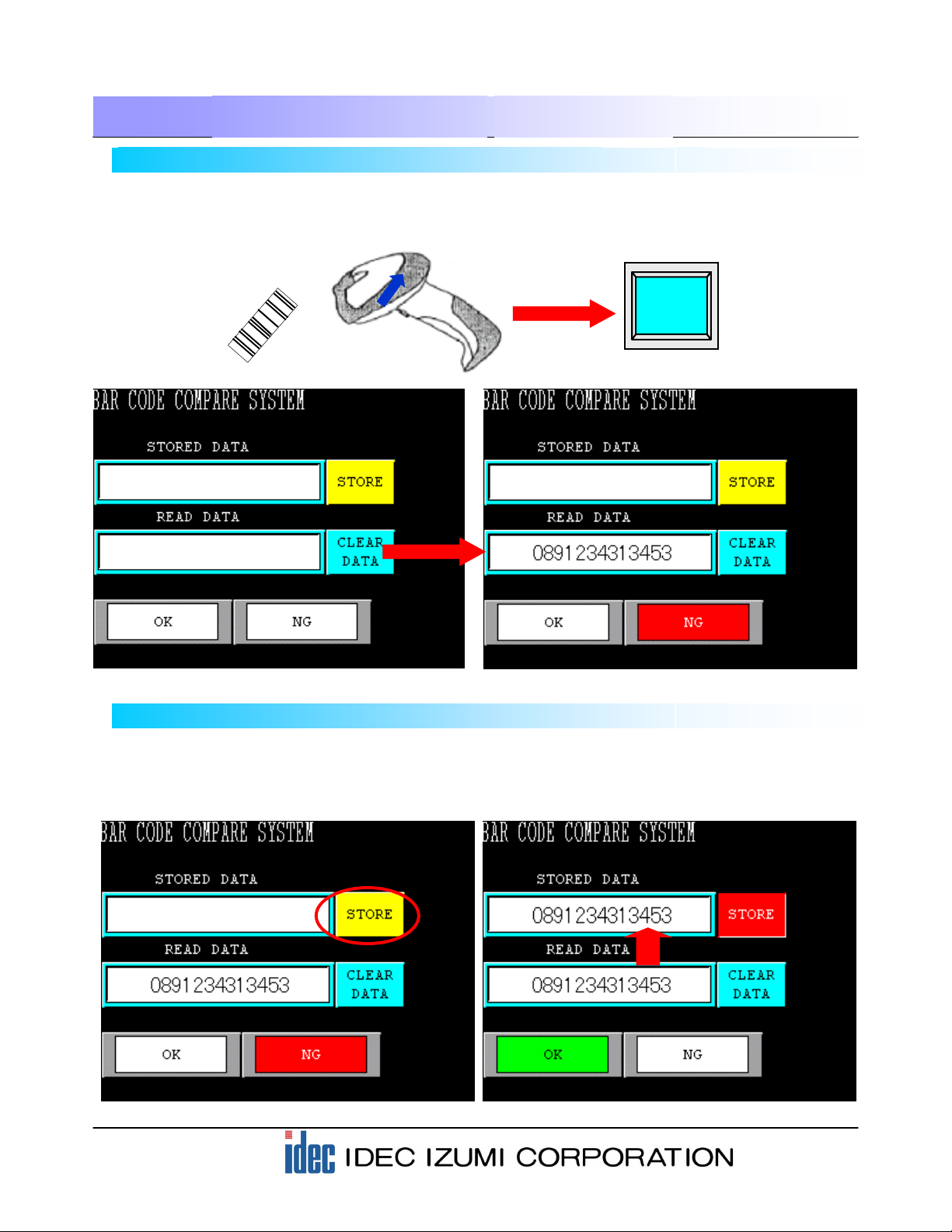
(1) Display area of registered barcode data Displays the registered barcode data.
(2) Display area of scanned barcode data Displays the scanned barcode data.
(3) STORE button used for registering barcode data Pressing the STORE button allows you to register
the scanned barcode data to the display area of
registered barcode data.
(4) Pressing the CLEAR DATA button allows you to
clear the data of the barcode that has been
registered for verification.
(5) OK lamp The OK lamp illuminates when the registered
barcode data matches the scanned barcode data.
(6) NG lamp The NG lamp illuminates when the registered
barcode data does not match the scanned
barcode data.
This application software operates as follows: Register one type of 13-digit barcode data to the operator
interface, an “OK” is displayed on the screen when the data scanned with the barcode reader matches the
Stored Data. Otherwise, “NG” is displayed.
The following are the details of the operating procedure.
-Base Screen 1: Program Screen-
When the power is turned on, the following Program screen is displayed on the HG2F display.
Before activating the HG2F, make sure to connect the HG2F unit to the barcode reader by referring
to the illustration in “1-2 System configurations”.
…………..
……………..
..
…………….
……………………………………………….
……………………………………………….
CLEAR DATA button for clearing the
barcode registration
(1) Display area of
registered barcode data
(2) Display area of
scanned barcode data
(3) STORE button used for
registering barcode data
(4) CLEAR DATA button for
clearing the barcode
registration
(6) NG lamp
(5) OK lamp
5
2. Operating Procedures
2-3 Registering scanned barcode data
Next, register the scanned barcode data as STORED DATA.
Pressing the STORE button will transfer the barcode data displayed in the READ DATA area. At the same
time, the “OK” lamp illuminates because the READ DATA matches the STORED DATA.
2-2 Reading barcode data
Press the button of the barcode reader connected to the operator interface to scan a 13-digit barcode. On
the HG2F screen, the scanned barcode data is displayed in the READ DATA area. The”NG” lamp
illuminates because STORED DATA has not been registered.

6
2. Operating Procedures
Pressing the CLEAR DATA button will clear the barcode data registered as the STORED DATA.
2-4 Displaying “OK” or “NG” when reading barcodes
The “OK” lamp illuminates when the READ DATA matches the STORED DATA. The “NG” lamp
illuminates when the READ DATA does not match the STORED DATA.
2-5 Clearing the registered barcode data
7
3. User Communication Settings
3-1 Setting the Communication Interface settings
The [User Communication] function enables direct communications between the HG series operator
interface and a barcode reader via an RS-232C cable. This application introduces the settings of an HG2F
program, configured by WindO/I-NV2, for reading barcode data with a barcode reader GRYPHON D100
(Izumi Datalogic Co.).
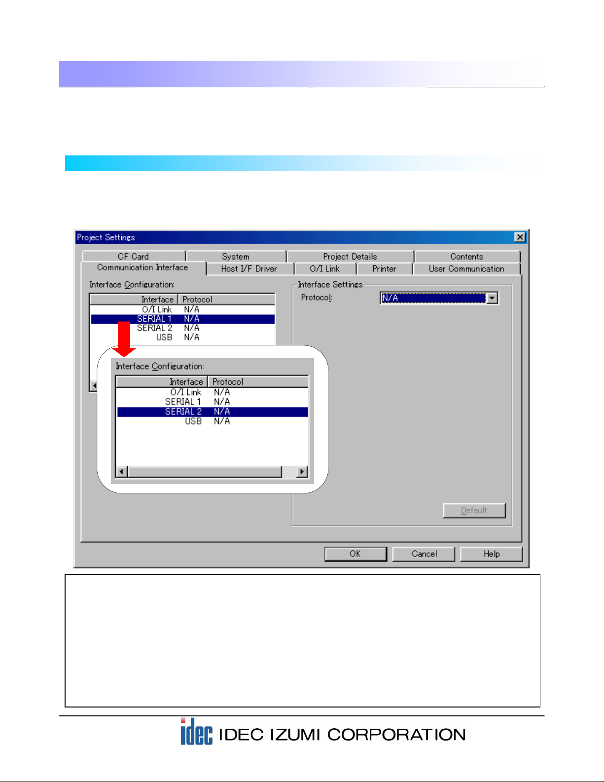
Select “Project Settings” from the “Setup” menu on the menu bar, and then select the “Communication
Interface” tab.
When the following dialog box is displayed, select “SERIAL 2” in the “Interface configuration” field,
because a barcode reader is to be connected to “SERIAL2” in this application.
[Supplementary note 1]
O/I Link…… An interface for the O/I link. The O/I unit should be attached to this interface.
SERIAL 1… An interface for communicating mainly to host devices (PLC, PC, etc.).
(D-sub 25-pin connector)
SERIAL 2… An interface used mainly for downloading project data from a PC or for connecting a serial
printer. (D-sub 25-pin connector)
USB………..An interface that can be used with HG2F units with USB. Cannot be used for user
communications.

8
3. User Communication Settings
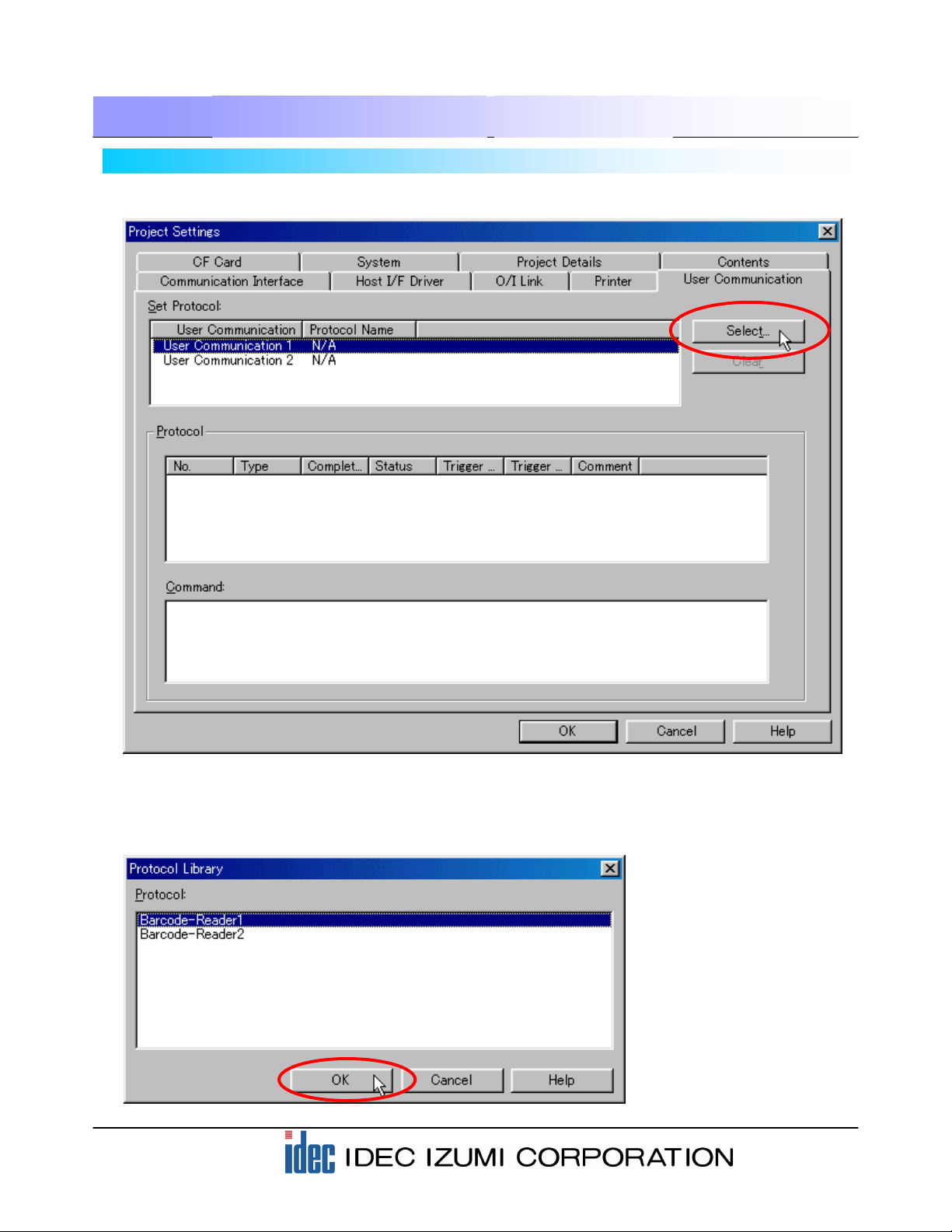
Select the protocol to be used with the interface you have selected in the previous step. Select “User
Communication 1” for the Protocol options in the “Interface settings” field, because the User
Communication function is used for connection to the barcode reader.
Selecting “User Communication 1” allows you to configure the detailed settings of the interface. The
barcode reader used in this example can be connected to the default values of WindO/I-NV2. Check that
the Baud Rate, Data Bits, Stop Bits, and Parity parameters are set as shown below.
When the settings are complete, the following screen is displayed.
Click the “User Communication” tab.
9
3. User Communication Settings
3-2 Setting the User Communication settings
Select “User Communication 1” and then click the [Select] button.
When the “Protocol Library” dialog box appears, select “Barcode-Reader 1” in the Protocol field, and then
click the [OK] button.
10
3. User Communication Settings
3-3 Protocol of barcode reader
The following are communication formats of a barcode reader that can be read with the HG series. Make
sure to set up the barcode reader settings properly.
STX [Barcode data (ASCII, variable between 1 and 30 digits)] CR LF
(02h) (0Ah) (0Dh)
Example: When the READ DATA of the barcode reader is 13 digits “1234567890123”:
STX 1 2 3 4 5 6 7 8 9 0 1 2 3 CR LF
02h 31h 32h 33h 34h 35h 36h 37h 38h 39h 30h 31h 32h 33h 0Ah 0Dh
Example: When the READ DATA of the barcode reader is 8 digits “12345678”:
STX 1 2 3 4 5 6 7 8 CR LF
02h 31h 32h 33h 34h 35h 36h 37h 38h 0Ah 0Dh
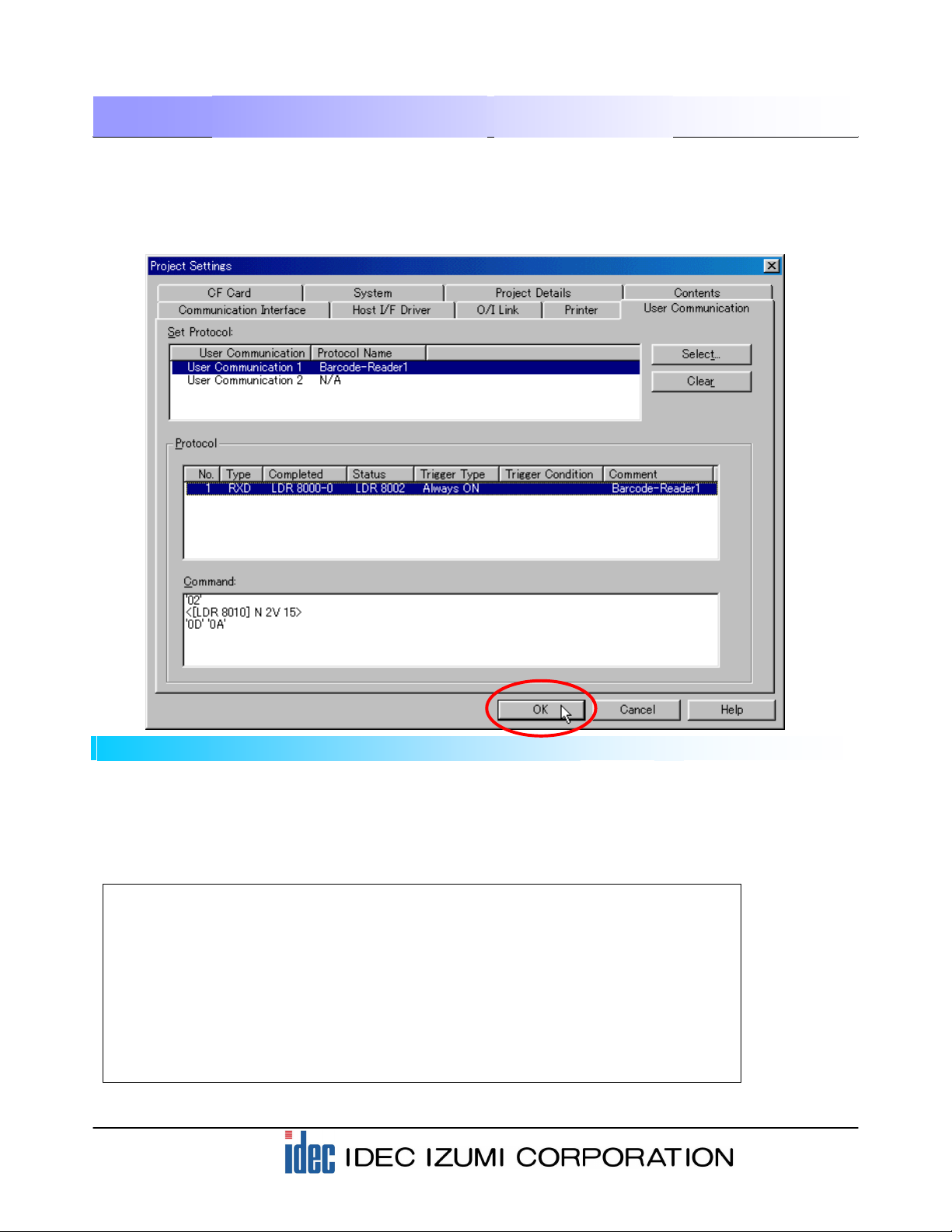
Check that “Barcode-Reader 1” is entered in the “Protocol Name” column for the User Communication in
the “Set Protocol” field. Selecting “No. 1” in the “Protocol” field in the dialog box will display the details of
the command in the “Command” window on the bottom.
After checking the settings, click the [OK] button. The settings for reading the barcode data with the
operator interface are now complete.
11
[Note] The devices marked with red dots:
The HG series operator interface is capable of reading barcode data of up to 30 digits. When barcode
data of less than 30 digits is read, “0000h” is written to all of the remaining devices.
For example, when 8-digit barcode data is read after reading an 13-digit barcode data, the 9th to 13th
digits of the previous data are overwritten by “0000h”. As a result, the Message Display displays the
barcode data of 8 digits only.
Storage location LDR8010 LDR8011 LDR8012 LDR8013 LDR8014 LDR8015 LDR8016 LDR8017 to LDR8024
Data "3132h" "3334h" "3536h" "3738h" "3930h" "3132h" "3300h" "0000h" "0000h" "0000h"
3. User Communication Settings
3-4 Device used with the barcode reader protocol
The data scanned by the barcode reader and the reception status are stored in the following devices. Data
reception is performed constantly.
[Supplementary note 2]
2 bytes of the barcode data loaded with the communications is stored in each register in ASCII data format.
Example: When 8-digit barcode data “12345678” is loaded, the data is stored as shown below.
Example: When 13-digit barcode data “1234567890123” is loaded, the data is stored as shown below.
Storage location LDR8010 LDR8011 LDR8012 LDR8013 LDR8014 to LDR8024
Data "3132h" "3334h" "3536h" "3738h" "0000h" "0000h" "0000h"
In this case, “0x00” is stored in the lower byte because the received data is with odd-numbered digits (13 digits).
Barcode-Reader1
Device Description
LDR 8000-0 Reception completion bit (Turns on when data reception is complete. <Automatically turned off.>)
LDR 8002 Reception status (Bit 0 to 14: reception data error under ON status; Bit 15: Timeout under ON
status <1 second>)
LDR 8003 Number of received bytes
LDR 8010 Received data 1, Received data 2
LDR 8011 Received data 3, Received data 4
LDR 8012 Received data 5, Received data 6
LDR 8024 Received data 29, Received data 30
Barcode-Reader2
Device Description
LDR 8050-0 Reception completion bit (Turns on when data reception is complete. <Automatically turned off.>)
LDR 8052 Reception status (Bit 0 to 14: reception data error under ON status; Bit 15: Timeout under ON
status <1 second>)
LDR 8053 Number of received bytes
LDR 8060 Received data 1, Received data 2
LDR 8061 Received data 3, Received data 4
LDR 8062 Received data 5, Received data 6
LDR 8064 Received data 29, Received data 30
* The received data is stored in LDR in ASCII data format by filling from the higher byte.
* When data with odd-numbered digits is received, the data is stored in the higher byte and “0x00” is
stored in the lower byte.

12
4. Description of the Program
4-1 Device allocations of the program screen
(1) Display area of registered barcode data Message Display: Displays (LKR100 to LKR109).
(2) Display area of scanned barcode data Message Display: Displays (LDR8010 to
LDR8019).
(3) STORE button used for registering barcode data Word Button: Transfers the data (LDR8010 to
LDR8019) to (LKR100 to LKR109).
(4) Word Button: Transfers the data “0” to each of
(LKR100 to LKR109).
(5) OK lamp Pilot Lamp: Illuminates when (LDR100= 127) is
true.
(6) NG lamp Pilot Lamp: Illuminates when (LDR100= 127) is
NOT true.
.....................
……………….
…..
……..
…………………………………………………
…………………………………………………
CLEAR DATA button for clearing the barcode
registration
(1) Display area of
registered barcode data
(2) Display area of
scanned barcode data
(3) STORE button used for
registering barcode data
(4) CLEAR DATA button for
clearing the barcode
registration
(6) NG lamp
(5) OK lamp
13
4. Description of the Program
4-2 Displaying barcode data
“Message Display” is a screen that is available with the operator interface is used for displaying the
barcode data. A Message Display is capable of displaying text data (ASCII or Shift-JIS code) in the
operator interface and PLC or other devices.
On the Program screen in this example, READ DATA and STORED DATA can be displayed.
The following section describes the setting procedure using WindO/I-NV2.
(1) Select the “Message Display” icon from the toolbar.
Set up the STORED DATA display using a similar procedure.
* The descriptions for the “View” and “Format” settings are omitted in this text. For these descriptions,
refer to the section “Parts” in Chapter 5 “Draw and Parts Objects” in the Instruction Manual.
(2) Enter “\@” to display a variable
message.
(4) Designate the Reference Device
setting to “LDR 8010”.
(5) To display 13-digit data in this sample,
designate “7”. (2-digit data is stored in
1 word.)
(3) Select “Ch1”.
(7) Click the [OK] button.
(6) When the settings of step (1) through (4) are
complete, click the [Set] button. The specified
display appears in the “Ch1” column of the
Variable field.
Reference Device: “LKR 100”
Words: “7”
14
4. Description of the Program
4-3 Creating the STORE button for the barcode data
A “Word Button” is available with the operator interface is used for creating the STORE button for the
barcode data. In this example, use the Move function of the Word Button to copy the value of the READ
DATA to STORED DATA.
(2) To use the “Move” function in this
sample, set the “Action Mode” to
“Move”.
(4) To transfer 7 words, set “7” in the
Transfer field.
(5) Assign the destination device to
where the data is to be transferred.
Specify “LKR 100” here.
(1) Select the Word Button from the toolbar. When the Properties of Word Button dialog box is displayed,
click the [Advanced>] button to start the setting.
Storage location LDR8010 LDR8011 LDR8012 LDR8013 LDR8014 LDR8015 LDR8016
Data "3132h" "3334h" "3536h" "3738h" "3930h" "3132h" "3300h"
Transfers 7-word data.
Storage location LKR 100 LKR 101 LKR 102 LKR 103 LKR 104 LKR 105 LKR 106
* The descriptions for the “View” and “Format” settings are omitted in this text. For these descriptions,
refer to the section “Parts” in Chapter 5 “Draw and Parts Objects” in the Instruction Manual.
(3) Designate the source device from
which the data is transferred.
Specify “LDR 8010” here.
(6) Click the [OK] button to complete
the settings.

15
4. Description of the Program
4-4 Creating the CLEAR DATA button for the barcode data
A “Word Button” is available with the operator interface and is used for creating the CLEAR DATA button
for the barcode data. In this example, use the Set function of the Word Button to copy “0” to STORED
DATA.
(2) To use the “Set” function in this
example, set the “Action Mode”
to “Set”.
(5) To transfer 7 words, set “7” in
the Transfer field.
(4) Designate the destination device
to where the data is to be
transferred. Specify “LKR 100”
here.
(1) Select the Word Button from the toolbar. When the Properties of Word Button dialog box is displayed,
click the [Advanced>] button to start the setting.
Transfers 7-word data.
Storage location LDR8010 LDR8011 LDR8012 LDR8013 LDR8014 LDR8015 LDR8016
Data 0000000
Storage location LKR 100 LKR 101 LKR 102 LKR 103 LKR 104 LKR 105 LKR 106
* The descriptions for the “View” and “Format” settings are omitted in this text. For these descriptions,
refer to the section “Parts” in Chapter 5 “Draw and Parts Objects” in the Instruction Manual.
(3) Designate the Value of the
Source Data. Specify “0” here.
(6) Click the [OK] button to complete
the settings.
Stored Data

16
4. Description of the Program
4-5 Judging the match or mismatch of barcode data
The comparison between the READ DATA and STORED DATA is performed using the following
procedures.
Storage location LKR 100 LKR 101 LKR 102 LKR 103 LKR 104 LKR 105 LKR 106
Storage location LDR8010 LDR8011 LDR8012 LDR8013 LDR8014 LDR8015 LDR8016
Compare Compare Compare Compare Compare Compare Compare
When data matches
(1) The READ DATA (LDR8010 to 8016) is compared to the STORED DATA (LDR100 to 106)
successively word by word. When the data matches, the corresponding LDR100-0 to LDR100-6 is
turned on. (Refer to the tables below.)
Comparison result LDR100-0 LDR100-1 LDR100-2 LDR100-3 LDR100-4 LDR100-5 LDR100-6
ValueofLDR1001248163264
(2) When the READ DATA matches the STORED DATA completely, all of the LDR100-0 to LDR100-6 are
turned on, and then the value of LDR100 is added.
Therefore, the system judges the data as being “matched” when the value of LDR100 is “127”, and as
“mismatched” when the value of LDR100 is other than “127”.
4-6 Barcode comparison settings
The READ DATA (LDR8010) is compared to the STORED DATA (LKR100). Using a part “Bit Write
Command” for the comparison.
(1) Click the “Bit Write Command” from the toolbar to open the dialog box.
Comparison result LDR100-0 LDR100-1 LDR100-2 LDR100-3 LDR100-4 LDR100-5 LDR100-6
ValueofLDR1001248163264
[OK] case…When all data items match, the LDR always becomes “127”.
LDR100 = 1 + 2 + 4 + 8 + 16 + 32 + 64 = 127
Comparison result LDR100-0 LDR100-1 LDR100-2 LDR100-3 LDR100-4 LDR100-5 LDR100-6
Value of LDR100 1 0 4 8 16 32 64
[NG] case…When the 4th digit does not match, LDR100 will not be “127”.
LDR100 = 1 + 0 + 4 + 8 + 16 + 32 + 64 = 125
17
4. Description of the Program
(7) Compare each of LDR8011 to LDR8016 with each of LKR101 to LKR106 using the above procedure,
and specify the respective comparison results as LDR100-1 to 6.
(2) When the “Bit Write Command” dialog box is displayed,
configure the Trigger Condition settings first.
(3) Select “While satisfying the condition”
in the Trigger Type field.
(4) Click the […] button on the right of the
Condition field to open the “Trigger Condition
Settings” dialog box and configure the
settings as shown below so that the bit write
command is executed when “LKR100”
matches “LDR8010”.
After configuring the settings, click the [OK]
button. The specified mathematical formula is
stored in the Condition field.
(5) Select the “General” tab and select the Destination
Device. Set the parameter to “LDR100-0” here.
(6) Click the [OK] button to
complete the settings.

18
4. Description of the Program
4-7 Judging the barcode data matching
When the READ DATA matches the STORED DATA completely, LDR100-0 to LDR100-6 are turned on
and the value of LDR100 becomes “127”. Configure the setting so that the [OK] lamp is turned on under
this condition.
(1) Click the “Pilot Lamp” icon from the toolbar to open the dialog box.
(4) Designate “127==LDR100” to the Condition field.
As described on the previous page, click the […]
button on the right of the Condition field to open
the “Trigger Condition Settings” dialog box and
configure the settings as shown below.
(5) Set up the [NG] lamp using a similar procedure. Make sure that the Condition in the Trigger Condition
of the [NG] lamp is “127!=LDR 100”. (!= indicates “mismatch”.)
* The descriptions for the “View” and “Format” settings are omitted in this text. For these descriptions,
refer to the section “Parts” in Chapter 5 “Draw and Parts Objects” in the Instruction Manual.
(2) When the “Properties of Pilot Lamp” dialog box is
displayed, configure the Trigger Condition settings first.
(3) Select “While satisfying the
condition” in the Trigger Type field.
19
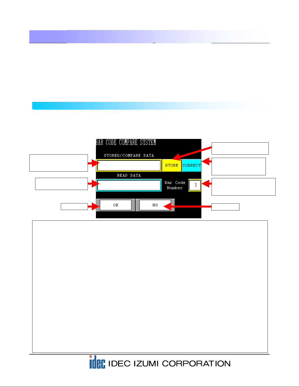
5. Advanced Program for Barcode Comparison
5-1 Program screens
(1) Display and entry area of barcode STORED/ COMPARE DATA
The registered barcode data can be displayed here. Pressing the display will display the character
keys, allowing you to modify the registered barcode data.
(2) Display area of scanned barcode data
Displays the scanned barcode data.
(3) STORE button used for registering barcode data
Pressing the STORE button allows you to register the scanned barcode data to the display area of
the scanned barcode data.
(4) CORRECT button used for modifying the barcode data
Pressing the CORRECT button allows you to modify the data in the display area of the verification
barcode and then register the data again.
(5) Display and entry area of barcode number STORED/ COMPARE DATA
The barcode number to be registered and verified is displayed in this area. Pressing the numeral
will display a numeric keypad, allowing you to enter the barcode number to be registered or
verified.
(6) OK lamp
The OK lamp illuminates when the stored barcode data matches the scanned barcode data.
(6) NG lamp
The NG lamp illuminates when the stored barcode data does not match the scanned barcode data.
This application program compares the scanned barcode with 50 types of pre-registered barcodes, (up to 20
digits, alphanumeric characters can be used), and then displays “OK” when the data matches or “NG” when
the data does not match. After configuring the barcode protocol using User Communications, import the
Advanced Barcode Comparison Application Program to your screen with the “Import Screens (*)” function. The
screen can be used easily for barcode comparison without creating software for registering barcodes and for
comparison operation.
The following section describes the details of the operating procedures.
-Base Screen 1: Program Screen-
When the power is turned on, the following Program screen is displayed on the HG2F display.
Before activating the HG2F, make sure to connect the HG2F unit to the barcode reader by referring
to the illustration in “1-2 System configurations”.
* Procedure for using the Import Screens function: Refer to the section “Importing Screens” in Chapter 4
Screen Management of the WindO/I-NV2 Online Manual (Select “Help” from the menu bar).
(1) Display and entry area
of barcode STORED/
COMPARE DATA
(2) Display area of
scanned barcode data
(3) STORE button used for
registering barcode data
(4) CORRECT button
used for modifying the
barcode data
(5) Display and entry area of
barcode number STORED/
COMPARE DATA.
(6) OK lamp (7) NG lamp
...
...
...
...
...
...
...
20
5. Advanced Program for Barcode Comparison
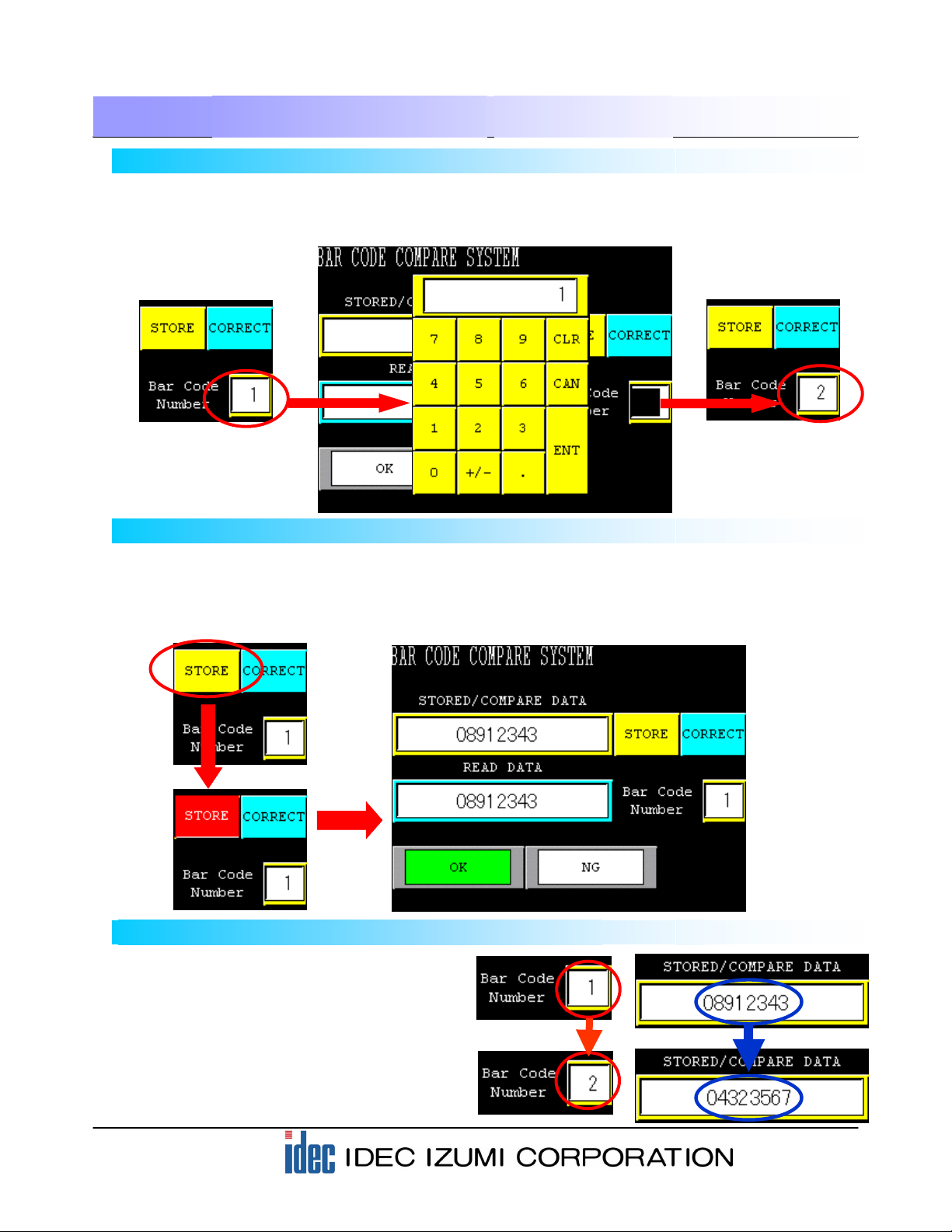
5-2 Entering the barcode number for registration and verification
Before registering a barcode, enter the “Bar Code Number” you want to register. Press the display area of
the Bar Code Number on the screen. When a numeric keypad is displayed, enter the number with which
you want to register (verify) the barcode data.
0
5-3 Registering the scanned barcode data
When actually scanning a barcode, press the [STORE] button on the screen. While the button is inverted
to red, press the button on the barcode reader to scan the barcode. When the scan is complete, the
scanned barcode data is displayed, the display of the [STORE] button returns to its original state, and the
[OK] lamp illuminates.
5-4 Calling the barcode for registration and verification
After registering barcode data, use the
numeric keypad described in step 5-2 for
calling the registered barcode data.
Change the number with the numeric keypad
to call up corresponding registered barcode
data as the barcode used for verification.
Table of contents
Other IDEC Recording Equipment manuals


