IDEC SE1L User manual
SE
1
L
Safety Laser Scanner
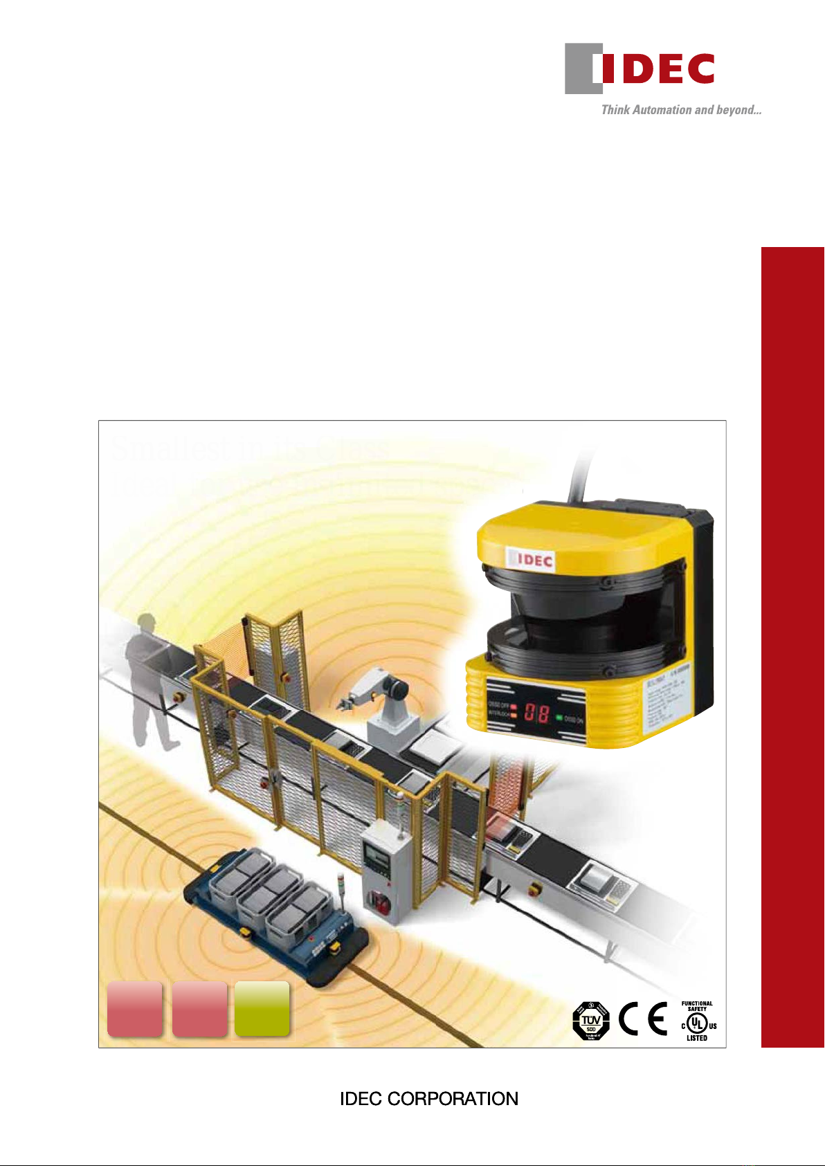
Smallest in its Class
Ideal for use in limited spaces
Smallest in its Class
Ideal for use in limited spaces
Ideal for use in limited spaces
SE
1
L
Safety Laser Scanner
Smallest in its Class
Ideal for use in limited spaces
IP65
Protection
Degree
Type 3 PLd
SIL2
(14/04/28)
Straight
Warning Zone 2
Warning Zone 1
Protection Zone
Production
Line
Production
Line
Station
Right turn
PLd
SIL2
Muting
Function
IP65
Protection
Degree Adjustable
Response
Time
Override
Function
48
areas
maximum
Easily
Visible
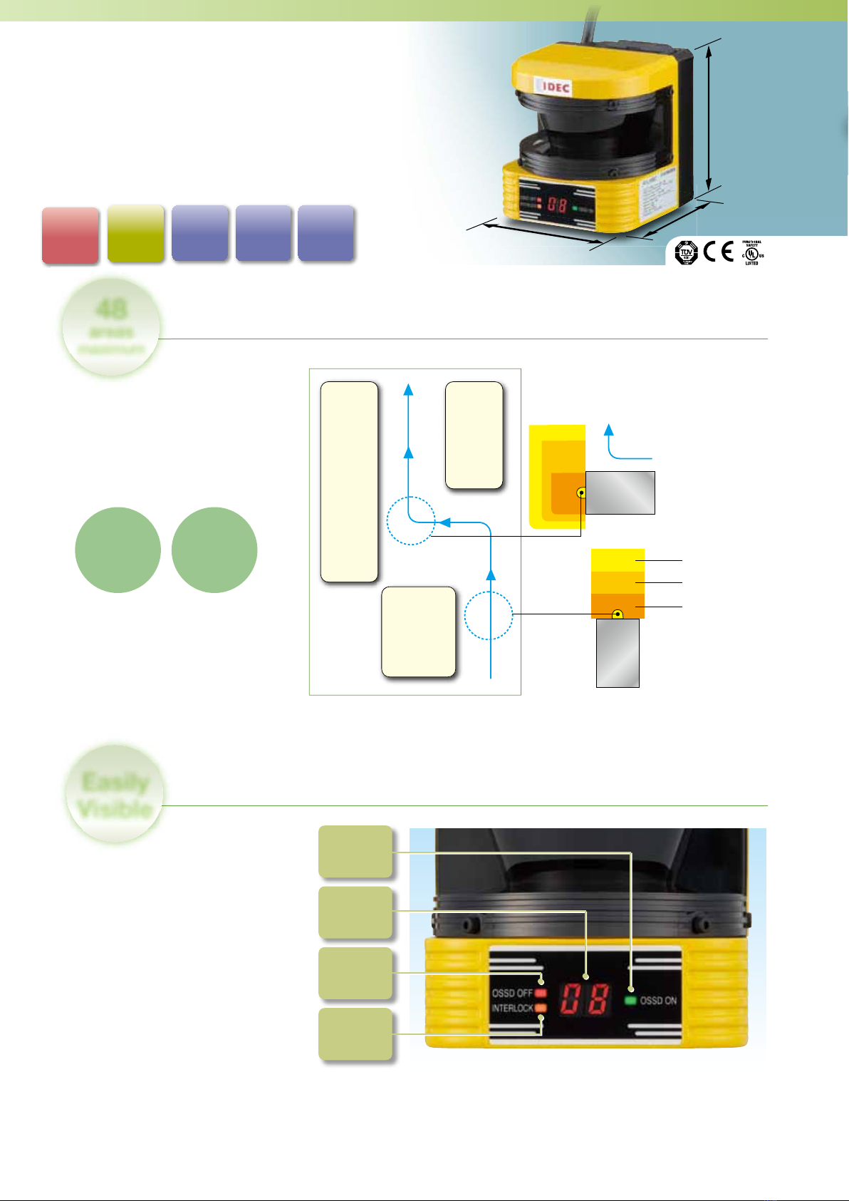
97mm
90mm
99.8mm
2
Warning
Zone
10m
max
Protection
Zone
2m
max
Find out operational status at a glance
The selected area number or error
number is displayed on the 7-segment
display on the front of the safety laser
scanner. The operation status is easy
to monitor.
Total of 3 zones −1 protection zone
and 2 warning zones, can be set for
1 area. Up to 16 area patterns can
be congured depending on speed,
direction, and surrounding conditions
from external signals.
Compact and Lightweight
Safety Laser Scanner
SE1L
Stores 16 area patterns3 zones
AGV traveling route example
OSSD
ON LED (green)
ON when the
OSSD signal is ON
OSSD
OFF LED (red)
ON when the
OSSD signal is OFF
INTERLOCK
LED (orange)
ON during
an interlock status
7-Segment
Display
(14/04/28)

(image)
before
Some areas were
disabled even when
protection was needed
When light curtains are used
SE1L
Hazardous areas are
minimized, enhancing
safety
(image)
When laser scanner is used
Starts smoothly
No need
to remove
object
Override Function
Protection area
SE1L
Reference area
Moving
part Moving
part
Floor
Protection
area
Reference
area
SE1L
Misalignment
Floor
Reference
area
SE1L
Object must be removed for restart
Remove
Object
No Override Function
Muting
Function
Override
Function
3
➁ Output OFF when mounting SE1L is misaligned
➀ Output OFF when
door opens
Override function enables safe restart of factory lines
Reference monitor function detects misalignment
Muting function enables flexible setting of protection zones
By configuring a reference point,
moving parts such as doors can
be detected when SE1L is not
correctly positioned, and turns off
the safety output (OSSD). Because
the misalignment of the SE1L can be
detected, hazardous areas can be
avoided, enhancing safety.
When a moving part is set as a reference point, the
output turns OFF when the door is opened.
With the override function, when a
light curtain is interrupted by an object
or when a line stops before muting
conditions are established (when only
one muting sensor is interrupted),
the object interrupting the light does
not have to be removed. Therefore,
the line can be started smoothly and
safely.
Specific areas of the protection zone
can be disabled by the muting sensor.
Complicated protection zones can be
configured easily.
(14/04/28)
4
SE1L
Mat
Sensor
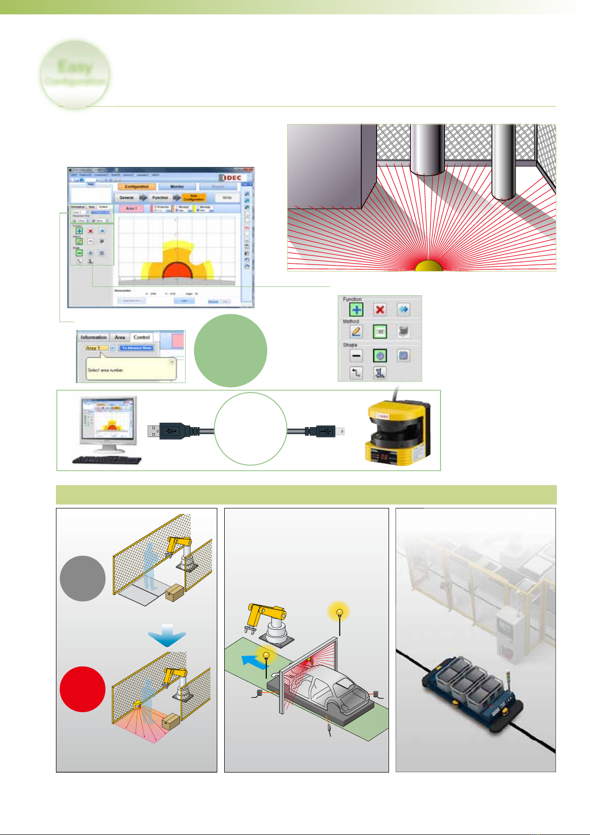
Easy
Conguration
Ideal for various applications
For presence
detection
For sites that require
muting function
To prevent collision of
AGVs (Automatic Guided
Vehicles)
xMat sensors may be
damaged if objects are
dropped on the mat.
xCannot be used if the
layout is changed.
xProtection zone is rectangular.
Specific areas of the protection zone can be
disabled, as with a light curtain.
16 patterns, 48 areas can be selected
according to the travel path of the
AGV.
xNo damage is
caused by falling
objects.
xLayout can be changed easily.
xThe shape of the protection zones can be changed.
Data transfer
via USB cable
Each item
can be set
Beginner mode for simple and comfortable operation
Simple layout and easy-to-use configuration
screen. With beginner mode, setting is easy.
Automatic setting is ideal for configuring
complicated protection zones, and for users not
having time for configuration.
Beginner mode
Auto configuration
(14/04/28)

5
SE1L Safety Laser Scanner
Smallest in its class. Ideal for installation in small spaces.
xEach area consists of 1 protection zone and 2 warning
zones. Up to 16 area patterns are available.
xOperation status is easily visible with a 7-segment
display.
xMuting function enables flexible configuration of areas
needing protection.
xOverride function enables safe restart of factory lines.
xMisalignment can be detected.
xDrawing methods can be selected from configuration,
numerical input, and auto setting. Beginner mode is
available to support inexperienced users.
xDegree of protection: IP65 (IEC 60529)
SE1L
Safety Laser Scanner Package Quantity: 1
Shape Part No. Remarks
SE1L-H02LP
Includes: SLS Configurator (configuration CD software (manual), English/Japanese)
Applicable OS: Windows XP Professional edition
Windows Vista Business edition
Windows 7 Professional edition
Windows 7 Ultimate edition
Microsoft is a registered trademark of Microsoft Corporation in the United States and other countries.
Abbreviation
The abbreviations used in this catalog are as shown in the table below.
Abbreviation Description
OSSD Output signal switching device
AGV Automated guided vehicle
EMD External monitoring device
AOPDDR Active opto-electronic protective device responsive to diffuse reflection
MSCE Machine secondary control element
Accessories Package Quantity: 1
Name and Shape Part No. Remarks
Connector Cable
2/5/10 /20m
2m SE9Z-HS1-C002 yOne cable is needed for each safety laser scanner.
5m SE9Z-HS1-C005
10m SE9Z-HS1-C010
20m SE9Z-HS1-C020
USB Maintenance Cable
HG9Z-XCM42
yUsed to connect the safety laser scanner and PC.
yCable length: 2m
L-shaped Bracket
SE9Z-HS1-BK01
yUsed to change the horizontal angle alignment of the SE1L.
yAdjustable by 15 degrees total (7.5 degrees each direction)
(See page 7 for dimensions)
yMaterial: iron
yAttachment: bracket + M5 mounting screws (4 pcs)
Vertical Mount Bracket
SE9Z-HS1-BK02
yUsed to change the horizontal and vertical angle alignment of
the SE1L.
yAdjustable by 15 degrees total (7.5 degrees up and down, left
and right in each direction)
(See page 7 for dimensions)
yMaterial: iron
yAttachment: bracket + M5 mounting screws (4 pcs)
Functional
Safety
Production
monitored
Safety
tested
Type 3
PLd
SIL2
Protection
Degree
IP65
SE1L Safety Laser Scanner
Functional
Safety
Production
monitored
Safety
tested
Type 3
PLd
SIL2
Protection
Degree
IP65
(UL File No. E355642)
(14/04/28)

6
SE1L Safety Laser Scanner
Performance Specifications
Part No. SE1L-H02LP
Applicable Standards
IEC/EN 61496-1 (TÜV SÜD), IEC 61496-3 (TÜV SÜD, UL Listed),
IEC 61508 Part 1-7 (TÜV SÜD, UL Listed), IEC 62061 (TÜV SÜD),
EN ISO 13849-1 (TÜV SÜD), ISO 13849-1 (UL Listed), IEC 60825-1 (TÜV SÜD),
EN 50178 (TÜV SÜD), EN 55011 (TÜV SÜD), UL 508 (UL Listed),
ANSI/UL 1998 (UL Listed), UL 61496-1 (UL Listed), CSA C22.2 No. 14 (c-UL listed)
Safety
Performance
Type Type 3 (IEC 61496-1, IEC 61496-3, UL 61496-1)
Safety Integrity Level SIL 2 (IEC 61508, IEC 62061)
Performance Level PL d (EN ISO 13849-1, ISO 13849-1)
Category Category 3 (EN ISO 13849-1, ISO 13849-1)
Sensing
Characteristics
Protection Zone 2.0m maximum
Warning Zone 10m maximum (non-safety)
Additional Safety Distance (Note 1) +100 mm
Sensing Characteristics Black reflector sheet (1.85%) to retro-reflector sheet
Speed: 1.6 m/s max.
Sensing Angle 190°
Minimum Sensing Width
ø30 mm (maximum distance: 1.0m)
ø50 mm (maximum distance: 1.5m)
ø70 mm (maximum distance: 2.0m)
Scan Cycle 30 ms (rotating speed 2,000 rpm)
Area 16 patterns
Response Time OSSD output ON→OFF: 60 to 510 ms
OSSD output OFF→ON: 270 to 510 ms
Power Voltage 24V DC ±10%: power from converter
24V DC −30%/+20%: power from battery
Power
Consumption
Normal (without output load) 11W (Typ.)
Maximum (without output load) 19W
Maximum (with output load) 58W
PFHd (Note 2) 7.5×10⁻⁸
Output
OSSD1/2 (safety)
Output type (High side SW)
Output current (maximum: 500 mA)
Leakage current (maximum: 1 mA)
Cable (length: 20m AWG 26)
Allowable load (L/R=25 ms C=1μF)
WARNING1 (non-safety)
Output type (PNP transistor output)
Output current (maximum: 100 mA)
Leakage current (maximum: 1 mA)
Cable (length: 20m AWG 28)
WARNING2/ERR/MUT_OUT
(non-safety)
Output type (PNP transistor output)
Output current (maximum: 100 mA)
Leakage current (maximum: 1 mA)
Cable (length: 20m AWG 28)
READY/RES_REQ
(non-safety)
Output type (PNP transistor output)
Output current (maximum: 100 mA)
Leakage current (maximum: 1 mA)
Cable (length: 20m AWG 28)
Input
Number of Inputs
16 area switching (4 inputs × 2 channels)
EDM (external device monitoring) / RESET / MUTING1 / MUTING2 /OVERRIDE
(1 input × 1 channel)
Input Resistance 4.7kΩ
Cable Cable length: 20m AWG 28
Light Source Pulse laser diode (wavelength: 905 nm)
Laser class 1 (IEC 60825-1, 21 CFR Part 1040.10 and 1040.11)
Operating Conditions
Operating temperature: −10 to +55˚C (no freezing)
Storage temperature: −25 to +70˚C (no freezing)
Operating humidity: max. 95% RH (no condensation)
Storage humidity: No freezing and condensation
Surrounding Light Intensity (Note 3) 3000 lx maximum
Vibration Resistance Frequency: 10 to 55 Hz Sweep: 1 octave/minute
Amplitude: 0.35 mm ±0.05 mm
Shock Resistance Acceleration: 98 m/s2 (10G) Pulse duration : 16 ms
Dimensions 97.0H × 90.0W × 99.8D (mm)
Weight (approx.) 1.0 kg
Degree of Protection IP65 (IEC 60529)
Material Body: Aluminum diecast / Optical window: Polycarbonate
Cable Flying cable and waterproof connector / cable 300 mm / M16-19p
Interface Structure USB2.0 (USB mini B type connector)
Cable Length Cable length: 20m maximum AWG 22, 26, 28
Note 1: Additional distance of 200 mm is needed when the SE1L operates under high reflective background.
Note 2: Probability of failure per hour
Note 3: The angle between the sensing plane and the light source should be more than 5 degrees.
(14/04/28)
7
SE1L Safety Laser Scanner
61.8
(Scanning)
USB connector
10 52
35
4-M5
depth 8
97
99.8
Scan angle 190º
90
OSSD OFF
INTERLOCK OSSD ON
62.7 (Sensing plane)
Waterproof connector
99-5661-15-19 (Binder)
Connector cable
OSSD OFF
INTERLOCK OSSD ON
26.7
13.2
75
113
26.7
135
160
ø6.3
94.2 (Sensing plane)
60
124
15°
15°
Sensing plane
190º
OSSD OFF
INTERLOCK OSSD ON
26.7
13.2
75
113
26.7
135
160
ø6.3
94.2 (Sensing plane)
60
124
15°
15°
Sensing plane
190º
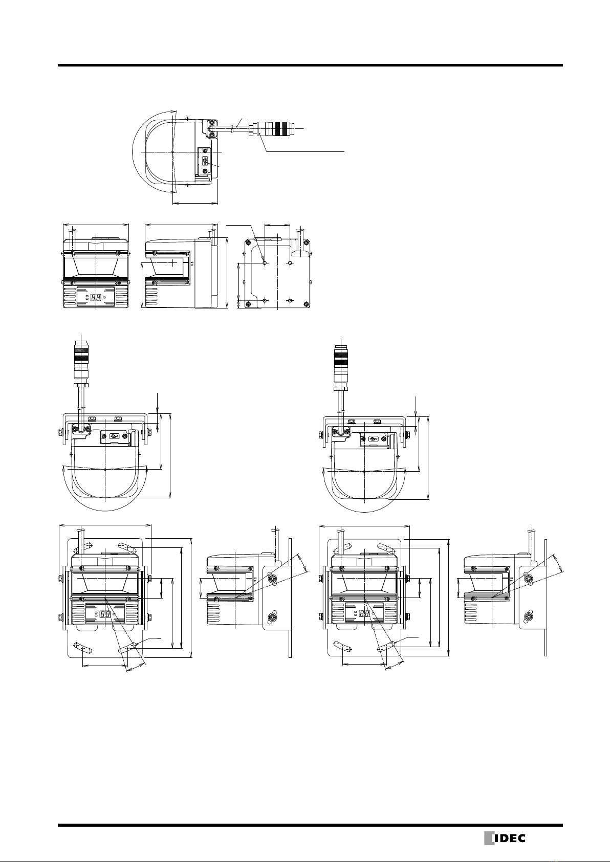
All dimensions in mm.
Dimensions
Safety Laser Scanner
L-shaped Bracket Vertical Mount Bracket
(14/04/28)
8
SE1L Safety Laser Scanner
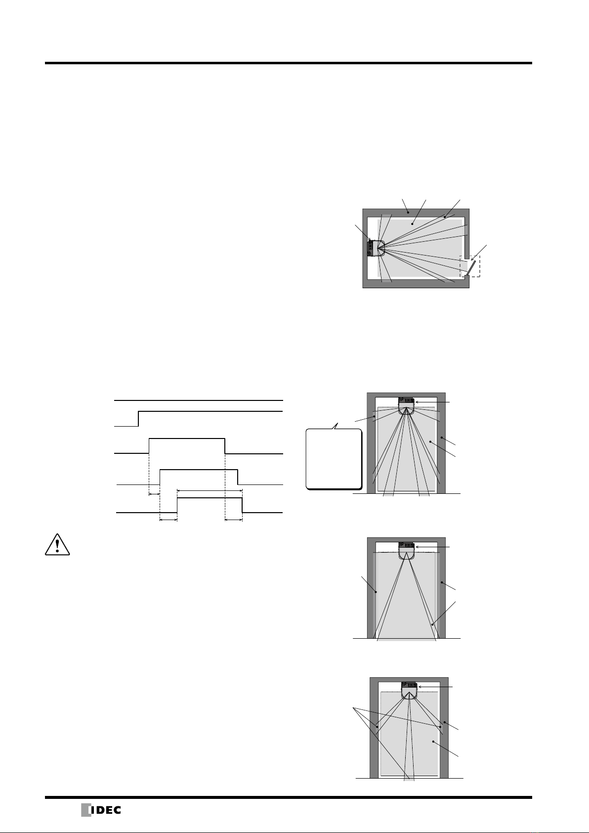
SE1L origin point
Unprotected
area
Protection
zone
180° 0°
90°
Warning
zone1
Warning zone 2
Similarly, when an object is detected in a warning zone,
the WARNING signal will turn OFF. The distance is
measured by the Time of Flight (TOF) principle. When
the motor rotates, the pulse laser beam is emitted within
the scanning range of 190º and is reflected back from an
object within the range. The distance can be calculated as
follows:
L =1
−
2× C × T
L = Distance to the object
C = Speed of light
T = Time difference
Operating Principle
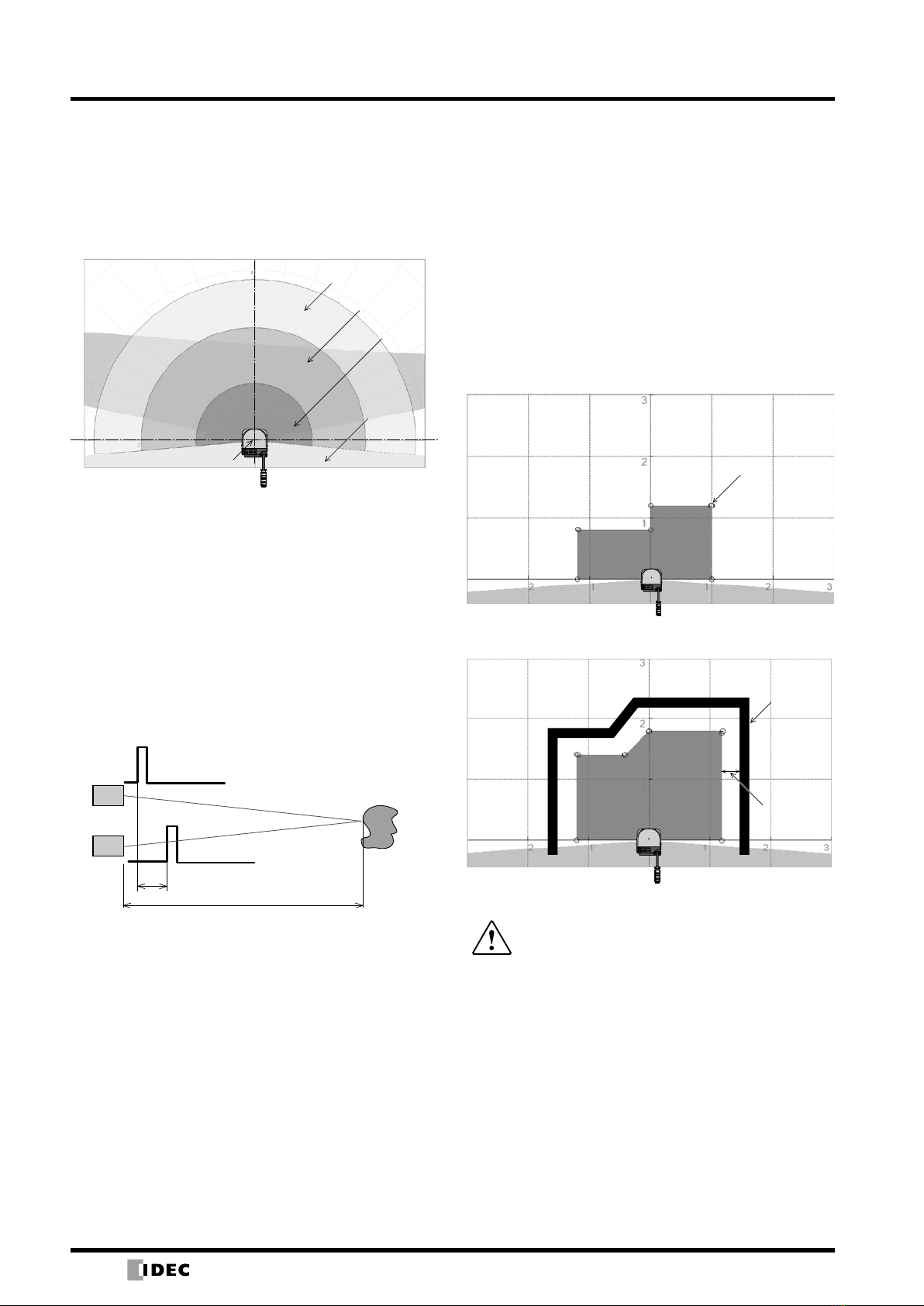
Scanning Range
The figure below shows the scanning range of the SE1L.
Protection zone and warning zones 1 and 2 are configured
using the SLS Configurator. When an object enters the
protection zone, the OSSD signal will turn from ON to OFF.
TOF Operating Principle
Object
Distance to object (L)
Photodiode
Laser
Time difference
Emitted pulse laser
Received pulse laser
Scanning Area
The scanning area of the SE1L consists of a protection
zone and two warning zones. A protection zone is an
area that is directly connected to an OSSD signal. When
an object is detected in the protection zone, the SE1L
switches the OSSD signal to OFF (triggers the switch that
stops the machine or the AGV). For moving applications,
the OSSD signal is used as an emergency stop signal.
Protection Zone
Below are examples of protection zones configured by
manual mode and auto mode with the SLS Configurator.
The operator must configure the software so that the
hazardous areas are fully protected.
Manual configuration of protection zone
Congurable
Points
Auto configuration of protection zone
Background
Distance
between
protection
zone and
background
xThe operator must test to make sure that the
protection zone is properly configured before
operation.
xThe configured protection zone must have a
minimum safety distance.
xThe minimum sensing width varies with distance.
xWhen setting the protection zone, take into
consideration additional safety distances.
Note:
xBefore operation, evaluate detection capability by using the actual object.
xFor details on SLS Configurator, see user’s manual.
TOF Operating Principle
(14/04/28)
9
SE1L Safety Laser Scanner
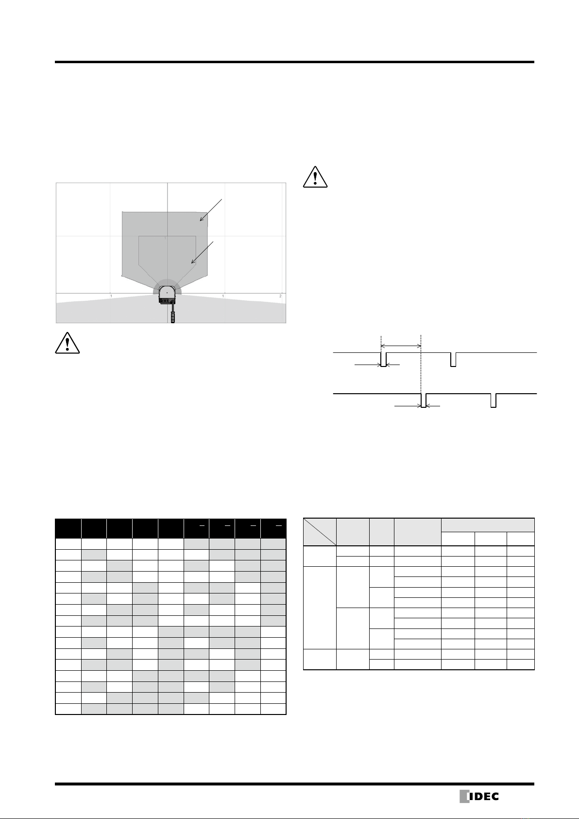
Warning Zone
The warning zone is a non-safety area and is connected to
WARNING 1 and 2 outputs.
When an object is detected within this zone, the WARNING
signal turns from ON to OFF. The warning signal can
be used as an alert signal to prevent humans or objects
approaching the protection zone. For moving applications,
warning zones can be used to reduce the speed of the
AGV to avoid collision.
Warning Zone 1
Warning Zone 2
OSSD
The OSSD signal is a safety signal. When humans are
detected inside the protection zone, the OSSD signal turns
from ON to OFF. Also the OSSD signal has a self-diagnosis
function that tests the signal periodically to detect
malfunction. The OSSD signal will turn OFF when a error is
detected due to the self-diagnosis function.
xThe OSSD is a safety signal and should be
connected directly to a force guided relay or a
device that controls the machine or AGV.
xWhen setting the response time of the OSSD
signal, provide sufficient time to stop operation
of the machine or AGV.
xThe operator must test to make sure the settings
are properly configured before operation.
Note: The signal is 24V when the OSSD signal is ON and 0V when OFF.
Self-Diagnosis Function of the OSSD
The self-diagnosis function of the OSSD detects
abnormality by switching OSSD 1 to OSSD 2 at intervals
of 300 µs maximum. Therefore, a safety relay or converter
must not respond to this self-diagnosis function.
Time chart
30ms
300μs
300μs
OSSD1
OSSD2
OSSD Signal and Condition of SE1L
The OSSD signal will switch to OFF (0V) when an object
enters a protection zone or when a error is detected by the
self-diagnosis function. By observing the READY signal
and ERR signal with OSSD signal, the operator is able to
recognize the condition of the SE1L. Below shows the
start-up status and operating status between the OSSD,
READY, and ERR signals.
Relationship between OSSD, READY, and ERR signals
Item
Status
Self-
Diagnosis
Function
Object Interlock
Configuration
Signal
OSSD READY*2ERR*3
Start-up
Status
OK − − OFF OFF OFF
FAIL − − OFF OFF OFF
Operating
Status
OK
YES Disabled OFF ON ON
Enabled OFF OFF ON
NO Disabled ON ON ON
Enabled OFF/ON*4ON/OFF*4ON
FAIL*1
YES Disabled OFF ON OFF
Enabled OFF OFF OFF
NO Disabled OFF ON OFF
Enabled OFF OFF OFF
Lockout FAIL − Disabled OFF OFF OFF
− Enabled OFF OFF OFF
*1:The SE1L will switch to a lockout state when a failure occurs
during self-diagnosis.
*2:When the interlock is enabled, the READY signal will change to
a lockout state.
*3:When the ERR signal is congured.
*4:When the conguration of start/restart is set to manual/manual,
the OSSD is OFF and READY is ON. When set to manual/auto,
OSSD is ON, and READY is OFF.
xA non-safety signal is the output from the
warning zone.
xDo not use the warning zone output signal to
control machines or AGVs for safety purposes.
Note:
xWARNING signal is a non-safety signal.
xWarning signals 1 and 2 are not related to the OSSD signal.
Area Switching
The SE1L can store up to 16 area patterns. Each area
consists of a protection zone, warning zone 1, and
warning zone 2. To switch areas, an external input signal
is required. Table below shows the combinations of input
signals for switching areas.
The number of the current area is displayed on the
7-segment display of the SE1L. The switching time of
areas can be configured.
Area switching combinations
Area
Pattern IN_A IN_B IN_C IN_D IN_A IN_B IN_C IN_D
1 ON ON ON ON OFF OFF OFF OFF
2 OFF ON ON ON ON OFF OFF OFF
3 ON OFF ON ON OFF ON OFF OFF
4 OFF OFF ON ON ON ON OFF OFF
5 ON ON OFF ON OFF OFF ON OFF
6 OFF ON OFF ON ON OFF ON OFF
7 ON OFF OFF ON OFF ON ON OFF
8 OFF OFF OFF ON ON ON ON OFF
9 ON ON ON OFF OFF OFF OFF ON
10 OFF ON ON OFF ON OFF OFF ON
11 ON OFF ON OFF OFF ON OFF ON
12 OFF OFF ON OFF ON ON OFF ON
13 ON ON OFF OFF OFF OFF ON ON
14 OFF ON OFF OFF ON OFF ON ON
15 ON OFF OFF OFF OFF ON ON ON
16 OFF OFF OFF OFF ON ON ON ON
xSee the user’s manual for details.
(14/04/28)
10
SE1L Safety Laser Scanner
Lockout
When an error is detected by the self-diagnosis function
normal operation cannot be performed, and SE1L will
change to a lockout state. In this condition, the OSSD1, 2
and WARNING 1, 2 signals turn OFF. Only when the cause
of the error is removed and the power is reset, the lockout
state can be cleared.
Relations between OSSD output and ERR output
Cause OSSD ERR
Object detection OFF ON
Device error OFF OFF
OSSD Interlock
Interlock is a function to prevent the OSSD signal restarting
automatically from OFF to ON. The following functions can
be set using the SLS Configurator.
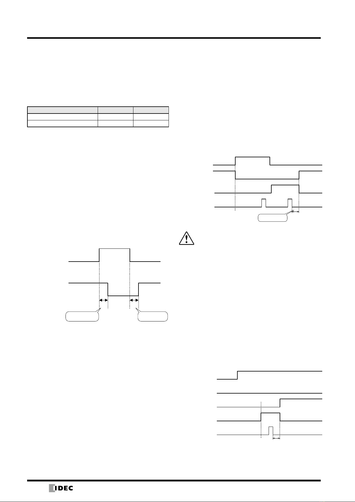
Automatic restart
When the interlock function is disabled or restart interlock
is set to automatic mode, the SE1L will operate in
automatic restart mode. When the objects in the protection
zone are removed, the OSSD signal will automatically turn
from OFF to ON.
In the figure below, “a” is the OFF delay and “b” is the ON
delay. However, if the OSSD signal changes due to lockout
of the sensor, the OSSD signal will remain OFF even when
the interlock function is disabled.
Time chart (automatic restart)
Object
Detection
ON
OFF
OSSD
ON
OFF
ba
OFF Delay ON Delay
Note:
xWhen using automatic restart, because the OSSD automatically turns ON
when the object is removed, take appropriate safety precautions.
xWhen using the delay function, make sure that the delay time is sufficient
to stop the machine or AGV.
Manual Restart
When the restart interlock is set to manual, the OSSD
signal will remain OFF even when the object in the
protection zone is removed or when an error is cleared. For
the SE1L to return to normal operation, an external reset
input signal is required to clear the interlock. The SE1L
will resume normal operation when there is a reset signal.
The time for the reset signal should be 0.5s minimum.
When the reset delay is set to “c” as shown in the figure
below, the OSSD signal will turn ON when the OSSD signal
reaches the delay time. However, if the OSSD signal turns
OFF due to internal failure, the OSSD signal remains OFF
regardless of the set delay time. The reset delay can be set
from 1 second to 6 seconds.
Time chart
c
ON
OFF
ON
OFF
ON
OFF
ON
OFF
Object
Detection
OSSD
RES_REQ
RESET
Reset Display
xThe operator must check that the object is
removed before resetting the SE1L.
xWhen using the manual restart to restart the
machine, the reset switch must be installed far
away from the protection zone.
xIf the above measures are not taken, critical
injury or death may result.
Note: If the OSSD signal remains OFF even when the object is removed
from the protection zone, check the error code and troubleshooting.
For details, see the user’s manual.
Manual Start
The configuration for start interlock can only be configured
manually. This function is used to maintain the OSSD in an
OFF state until the external reset signal is input at start-up.
The RES_REQ signal turns ON after start-up preparation
and ready to receive the reset signal. When the reset signal
is input, if there is no object in the protection zone, the
OSSD signal will turn ON. The input time of the reset signal
must be more than 0.5 seconds.
Time chart (manual start)
ON Delay
Ready for Operation
ON
OFF
ON
OFF
ON
OFF
ON
OFF
Power
OSSD
ON
OFF
Object
Detection
RES_REQ
RESET
(14/04/28)
11
SE1L Safety Laser Scanner
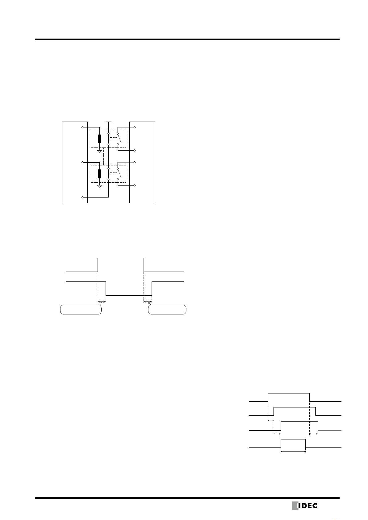
External Device Monitoring (EDM) Function
EDM function monitors the input signal status of a machine
or AGV. The SLS Configurator is used to configure the
EDM. When an EDM signal detects an error, the OSSD
signal turns OFF. The EDM input signal is always the
inverse of the OSSD signal. The EDM input signal ON/OFF
delay can be configured. Do not connect the EDM when
the EDM function is not used.
EDM Circuit
AOPDDR MSCE
OSSD_1
EDM
24V DC
NC
OSSD_2
NC
NO
NO
Note: When the EDM function is disabled, do not connect the EDM as an
error will occur.
Time chart
d
ON
OFF
ON
OFF
OSSD
EDM
e
EDM OFF Delay EDM ON Delay
Muting Function
Muting function is a function to temporarily stop the safety
function in the protection zone. During muting, the OSSD
signal will remain ON even when an object is detected
in the muting area. The muting function can be started
and stopped using two signals that are independently
wired. Muting areas can be configured using the SLS
Configurator. When the muting input satisfies the starting
conditions, the SE1L stops the safety function within 60
ms. (For details, see the user’s manual)
Muting Start
Muting function starts when the following conditions are
satisfied:
1) When OSSD is ON and there are no objects within the
protection zone.
2) 2 muting input signals which are independently wired are
switched to the preset input order or switched within the
time interval of T1.
To start muting, see the configuration below. The SLS
Configurator can be used for the configuration below. (For
details, see the user’s manual)
Muting input order
Muting 1 → Muting 2
Muting 2 → Muting 1
Input time difference (T1)
1 second
3 seconds
5 seconds
10 seconds
Muting Stop
Muting function stops when the following conditions are
satisfied:
1) Either one of the muting input turns OFF.
2) When the muting status exceeds the maximum muting
time T2.
3) When an object is detected in a protection zone that is
not covered by a muting area.
4) When an error is detected by a self-diagnosis function.
5) When the muting area is switched to a different area
during muting.
The following shows the necessary configuration to end
the muting function.
Maximum muting time (T2)
1 minute
6 minutes
12 minutes
Muting Sequence
ON
OFF
ON
OFF
ON
OFF
ON
OFF
Muting1
Muting2
MUT_OUT
Within maximum
muting time
MUT_OUT
When exceeding
maximum muting time
T1
≤60ms ≤60ms
T2
(14/04/28)
12
SE1L Safety Laser Scanner
Muting Override Function
Muting override function is used to temporarily stop all
safety functions of the entire protection zone when the
OSSD turns OFF during muting. The override function
is effective when the override input and reset input is
switched in the order as shown below. When the SE1L
is in a override status, the 7-segment display shows the
override code.
Override start condition
Either one of the muting input is ON.
When an object exists in the protection zone.
When the time interval of the override input and reset
input is between 0.03 and 1 second (T3)
Override stop condition
Both of the muting inputs are OFF.
Either the override input or reset input is OFF.
When the override state exceeds the maximum
override time T4.
When an error is detected by the self-diagnosis
function of the SE1L.
When the muting area switched to a different area
during muting.
Maximum override time (T4)
1 minute
6 minute
12 minute
Override Sequence
ON
OFF
ON
OFF
ON
OFF
ON
OFF
OFF
ON
Muting1
Muting2
Override input
Reset input
Override status
T4
T3
60ms 60ms
xWhen the muting function is effective, the user
must ensure the safety of the protection zone.
xBefore using the muting function, make sure to
perform a risk assessment.
xIf the above procedures are not followed, critical
injury or death may result.
Reference Monitor Function
The reference monitor function is a function to monitor
the displacement of the SE1L or the structure in the
background used as a reference.
Existence Detection Application Examples
When the reference area is set to a moving part such as
a door, the OSSD will turn OFF if the position of the door
changes.
Protection
zone
Reference background
SE1L
Reference area
Moving part
Access Detection Application Example
The user must configure the reference area for monitoring.
To detect the displacement, set a reference area on each
side. The OSSD will turn OFF when the distance between
the reference background has changed or when an access
is detected. This function must be used when the SE1L is
installed vertically.
(1) Application Example 1 (front view)
(2) Application Example 2 (front view)
SE1L
Floor
Protection zone
Reference background
Reference area
(Caution) Incorrect reference area configuration (front view)
SE1L
Floor
Protection zone
Reference background
Reference area
Floor
Protection zone
Reference background
Reference area
SE1L
Make sure that 2 or
more reference
areas are set to one
side of the reference
background so that
displacement is
detected correctly.
(14/04/28)
13
SE1L Safety Laser Scanner
Calculating Safety Distance
To use the SE1L as a safety equipment, take into
consideration the guidelines mentioned below.
1) The hazard must be identied before performing a risk
assessment.
2) Do not use the SE1L for nger protection.
3) Use under an operating environment within the
specications of the SE1L.
4) The safety distance must be determined in accordance
to ISO 13855 and IEC 61496-3.
xUsing sensors that exceed specifications may
lead to critical injury or death.
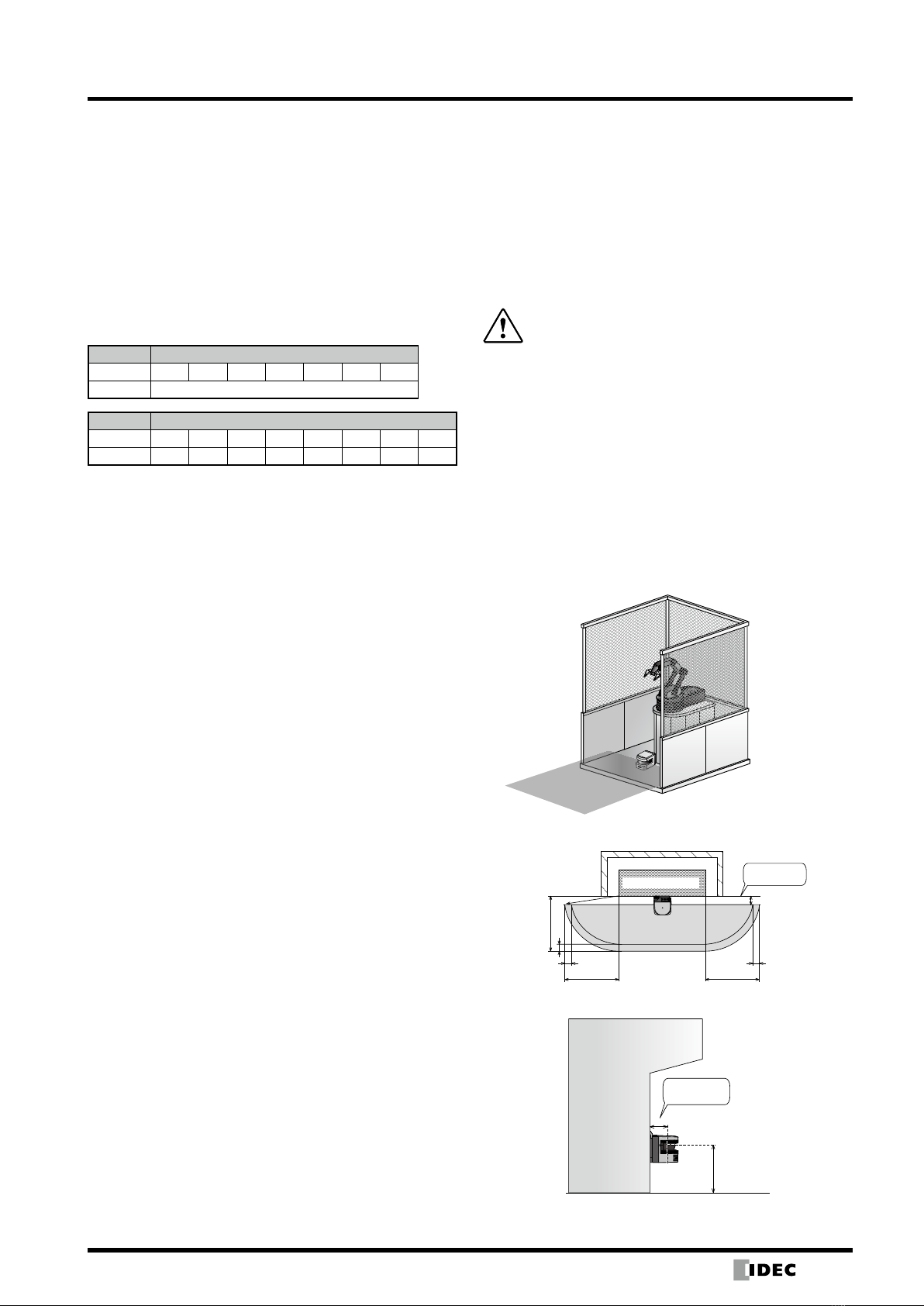
Hazardous Area Protection (Stationary)
In this application, the SE1L is horizontally installed to
protect the hazardous area. The protection zone is set
around the hazardous area to prevent humans or objects
from entering the hazardous area. Warning zones 1
and 2 are configured to surround the protection zone.
The warning zones prevent the machine from stopping
unnecessarily and can be used as a warning to humans or
objects that approach the protection zone. By detecting
humans or objects in the protection zone, the OSSD signal
switches from ON to OFF. Also, when humans or objects
are detected in the warning zone, the warning zone output
(WARNING signal) switches from ON to OFF.
Application example
Safety distance (upper view)
Unprotected
area
SHazardous area
Protection zone
S
Zs
Zs
a
Zs
S
S
Safety distance (side view)
H
a
Machine
Unprotected
area
Response Time
The response time for the OSSD signal can be configured
by the SLS Configurator. The response time for WARNING
1, 2 is the same as the response time for OSSD. The
stability of the SE1L can be increased by setting a long
response time, but a long safety distance is required. (See
Calculating the Safety Distance on page 13 to 15.) Before
setting the response time, the user must perform a risk
assessment. The configurable response time is shown in
the table below. Be sure to add the time taken to switch
areas (30 ms)
SE1L Response Time
Response Time (ms)
ON→OFF 60 90 120 180 210 240 270
OFF→ON 270
Response Time (ms)
ON→OFF 300 330 360 390 420 450 480 510
OFF→ON 300 330 360 390 420 450 480 510
Other Outputs
SE1L has 3 non-safety outputs such as WARNING1,
WARNING2/ERR/MUT_OUT, and READY/RES_REQ.
WARNING2/ERR/MUT_OUT (WARNING2 at default)
and
READY/RES_REQ (READY at default) use the same
output terminal and can be configured using the SLS
Configurator.
Warning Output (WARNING1)
This signal turns OFF when an object is detected in
protection area 1.
Warning Output (WARNING 2)
This signal turns OFF when an object is detected in
protection area 2.
Error Output (ERR)
ERR output shows the operating status of the SE1L. This
signal turns OFF when an error is detected by the self-
diagnosis function of the SE1L.
Muting Output (MUT_OUT)
MUT_OUT indicates the MUTING/OVERRIDE status of the
SE1L. When muting is activated, MUT_OUT turns ON. In
a muting status, the 7-segment display shows “18”. In an
override status, the display shows “19”. Use this signal to
indicate whether the SE1L is in a muting status.
Ready Output (READY)
This signal turns ON when the SE1L is ready for operation.
Reset Request (RES_REQ)
This signal turns ON when the SE1L is ready to receive the
reset signal.
(14/04/28)
14
SE1L Safety Laser Scanner
Calculation
S = (K × (Tm + Ts) + C + Zs
S = Safety distance (mm)
K = Human approach speed 1,600 (mm/s)
Tm = Maximum stop speed of machine or system (s)
Ts =Response time of SE1L (s)
C = 1200 − 0.4 × H ≥ 850
H = height from the floor to the sensing plane (mm)
1000 ≥ H ≥ 15 × (d − 50)
d = Minimum sensing width of object (mm)
Zs = Additional safety distance of SE1L (mm)
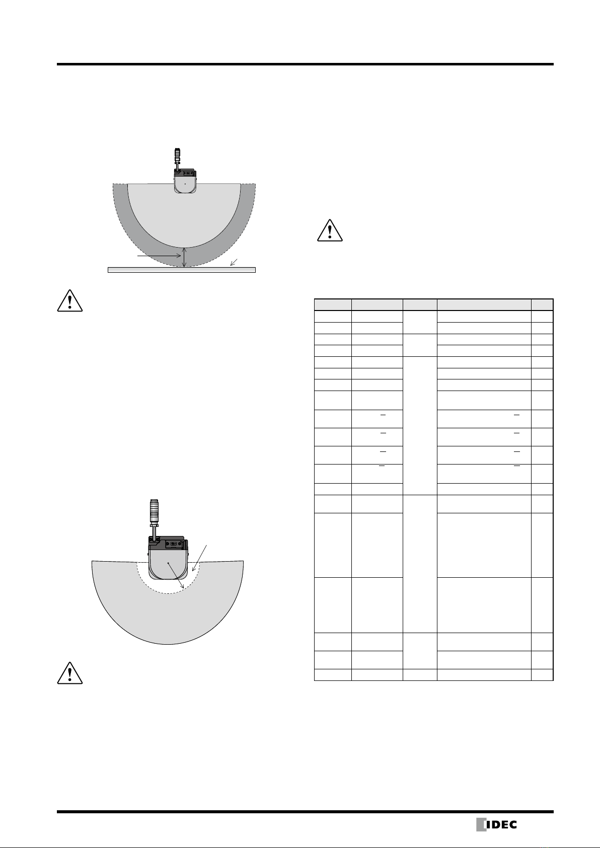
xInstall the SE1L so that the distance between the
end of the hazardous area and the origin of the
protection zone “a” is shorter than the minimum
sensing width. If the distance of “a” is longer
than the minimum sensing width, additional
protection measures must be taken so that
objects cannot enter the unprotected area.
xDo not install the SE1L higher than 300 mm
to prevent obstacles entering beneath the
sensing plane. If there is a need to install the
SE1L higher than 300 mm, take measures to
prevent obstacles entering beneath the detecting
surface.
xTo install the SE1L in a public area, make sure
that the height from the floor to the sensing plane
is within 200 mm or install according to local
height regulations.
xTo use the SE1L for presence detection (when
an object enters the protection area horizontally),
make sure to set the minimum sensing width to
less than 70 mm.
Note:
xIt is recommend that markings are placed on the floor so that the
protection zone is clearly defined.
xTo configure the safety distance, the additional safety distance must be
taken into consideration.
xWhen operating the SE1L in a high reflective background environment,
additional distance must be added.
xMake sure that protective measures or background are not detected in the
protection zone. If they are detected as an object, the OSSD remains OFF.
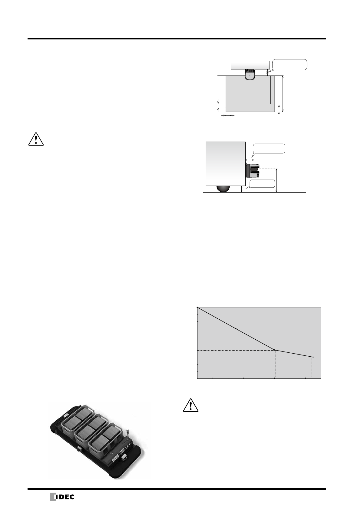
Hazardous Area Protection (Movable)
The SE1L can be used for movable applications. In an
application using an AGV, the SE1L on the AGV detects
humans or objects while traveling on the fixed route.
The warning zone signal is used to slow down the AGV
and the OSSD signal can be used to stop the AGV when
required. By using the area switching function of the SE1L,
the AGV can use 16 different area patterns based on its
traveling route. When using the SE1L on an AGV, take
into consideration the time needed for the AGV to stop
completely when configuring protection zones and warning
zones.
Application Example
Safety distance (top view)
Zs
a
Zg
Zs
Protection
zone
AGV
S
Non-protected
area
AGV
h
H
a
Ground
clearance
Non-protected
area
Calculation
S = V × (Tm+Ts) + Zb × L + Zs + Zg
S = Safety distance (mm)
V = Maximum approach speed of the AGV (mm/s)
Tm= Maximum stopping time of the machine or system (s)
Ts= Response time of SE1L (s)
Zb= Distance required for the AGV to stop (mm)
L = Brake friction coefficient
Zs= Additional safety distance of SE1L (mm)
Zg= Additional safety distance due to insufficient ground
clearance
h = ground clearance (mm)
To prevent damages to fingers, provide sufficient ground
clearance.
The graph below shows the relation between h and Zg.
20
30
40
50
60
70
80
90
100
110
120
020 40 60 80 100 120 140 160
Additional distance for insufcient ground clearance (mm)
Ground clearance h (mm)
xInstall the SE1L so that the distance between the
end of the hazardous area and the origin of the
protection zone “a” is shorter than the minimum
sensing width. If the distance of “a” is longer
than the minimum sensing width, additional
protection measures must be taken so that
objects cannot enter the unprotected area.
xDo not install the SE1L higher than 200 mm to
prevent objects entering beneath the sensing
plane.
Note: Make sure that protective measures or background are not detected
in the protection zone. If they are detected as an object, the OSSD
remains OFF.
(14/04/28)

15
SE1L Safety Laser Scanner
Access Detection (Detecting the Entire Body)
When constructing a protective shield, the SE1L can be
installed vertically. In the application below, it is used to
prevent access into hazardous areas. When an object
or human enters the hazardous area, the OSSD signal
switches from ON to OFF. When the SE1L is installed
vertically, an object or human is detected by the vertical
sensing plane. The front and rear of the sensing plane
cannot detect objects or humans. Therefore, the distance
between the approach and hazardous area must be
carefully determined. The reference monitor function must
be used for this kind of application. If a displacement
occurs within the reference background, the OSSD signal
turns OFF.
Application example
Safety distance (front view)
Zs
Zs
a
Protection
zone
Non-safety
area
Safety distance (side view)
Hazardous
area
Hazardous
area
S
Calculation
S = (K × (Tm + Ts) ) + C
S = Safety distance (mm)
K = Approach speed 1600 (mm/s)
Tm= Maximum stopping time of the machine or system (s)
Ts= Response time of SE1L (s)
C = Additional distance for entry of fingers 850 (mm)
xInstall the SE1L so that the distance between the
end of the hazardous area and the origin of the
protection zone “a” is shorter than the minimum
sensing width. If the distance of “a” is longer
than the minimum sensing width, additional
protection measures must be taken so that
objects cannot enter the unprotected area.
xFor access detection applications, if the
approach angle exceeds ±30º be sure to use the
“reference monitor function” The response time
must be 90 ms maximum for access detection
applications. Set the tolerance range of the
reference area to 100 mm.
xIn order to detect displacement, make sure to set
a reference area on each side.
xMake sure that the SE1L is installed in a way that
access to hazardous points is impossible. Take
additional protection measures if necessary.
xBefore setting the reference area, take into
consideration the tolerance range.
Note: When setting the minimum sensing width to 30 mm,
the value C can be replaced by 0.
Access Detection (Detecting Parts of a Body)
When constructing a protective shield, the SE1L can be
installed vertically. It is used to prevent a part of a body
from reaching a hazardous area. When an object or a part
of a body enters the hazardous area, the OSSD signal
switches from ON to OFF. When the SE1L is installed
vertically, the vertical side of the object or human is
detected. The front and rear of the sensing plane cannot
detect objects or humans. Therefore, the distance between
the approach and hazardous area must be carefully
determined. The width of the protection zone must be
configured to fully cover the hazardous area. The reference
monitor function must be used for this kind of application.
If a displacement occurs with the reference background,
the OSSD signal turns OFF. For details, see the user’s
manual.
Safety distance (side view)
Hazardous
area
Hazardous
area
S
Safety distance (front view)
Hazardous Area
Protection
Area
Reference
Background
O
O
(14/04/28)
16
SE1L Safety Laser Scanner
Calculation
S = (K × (Tm + Ts) ) + C
S = Safety distance (mm)
K = Approach speed 2000 (mm/s)
Tm = Maximum stopping time of the machine or system (s)
Ts = Response time of SE1L (s)
C = Additional distance
=8 × (d − 14)
d=minimum sensing width (mm)
O = Additional width from the end of the hazardous source
≥ (2 × Zs) − d
d=Minimum sensing width (mm)
Zs=Additional safety distance of SE1L (mm)
xFor access detection applications, if the
approach angle exceeds ±30º be sure to use the
“reference monitor function”
xConfigure the reference area to each side so that
displacement can be detected.
xSet the tolerance range of the reference area to
100 mm.
xIn order to detect displacement, make sure to set
a reference area on each side.
xMake sure that the SE1L is installed in a way that
access to hazardous points is impossible. Take
additional protection measures if necessary.
xBefore setting the reference area, take into
consideration the tolerance range.
Note: When S>500 mm, value K can be replaced by 1600 mm/s instead of
2000 mm/s. In this case, S must be larger than 500 mm.
Installation
Light Interference
SE1L is a sensor that transmits pulsed laser for obstacle
detection. Interfering light sources may lead to false
detection. Before using the SE1L, examine the surrounding
environment. Be sure to avoid the following light sources.
1) Incandescent light
2) Florescent light
3) Strobe light
4) Flashing beacon
5) Sunlight
6) Infrared light source
However, if the SE1L must be used under the above
environment, install the SE1L so that the light source is
located more than ±5 degrees from the sensing plane to
prevent light interference.
5 degrees
5 degrees
Sensing plane
Light source
Light source
Protection degree
origin point
xBe sure to perform a risk assessment for light
interference in the operating environment before
installing the SE1L.
xAvoid using direct interference light such as
fluorescent light, flashing beacons, or strobe
light.
xIf the above precautions are not followed, critical
injury or death may result.
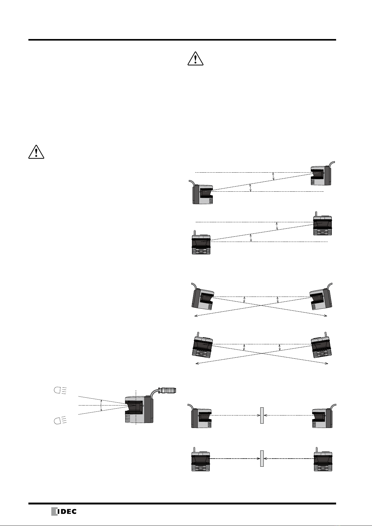
Mutual Interference
When using several SE1Ls of the same model, pulse laser
signals from different SE1Ls may be falsely detected. To
prevent mutual interference, see the installation methods
shown below.
1) Changing the installation height
Face to face installation
5 degrees minimum
5 degrees minimum
Parallel installation
OSSDOFF
INTERLOCK OSSDON
OSSDOFF
INTERLOCK OSSDON
5 degrees minimum
5 degrees minimum
2) Changing the installation angle
Face to face installation
Sensing
plane
Sensing
plane
5 degrees min.
Parallel installation
OSSDOFF
INTERLOCK OSSDON
OSSDOFF
INTERLOCK OSSDON
Sensing
plane
5 degrees min.
Sensing
plane
3) Using shields
Face to face installation
Sensing plane Sensing plane
Shield
Parallel installation
OSSDOFF
INTERLOCK OSSDON OSSDOFF
INTERLOCK OSSDON
Sensing plane Sensing plane
Shield
Note: Use a solid and non-transparent material for shields.
(14/04/28)
17
SE1L Safety Laser Scanner
Highly Reflective Background
Highly reflective backgrounds may cause false detection
causing the SE1L to detect a longer distance than the
actual distance. If an operating environment with a highly
reflective background cannot be avoided, an additional
distance of 200 mm is needed when configuring protection
or warning zones.
Additional distance ∗High reective
background
Protection zone
xWhen the background is highly reflective, the
detected distance may be longer than the actual
distance.
xWhen setting the protection zone, an additional
distance must be added.
xAvoid using a highly reflective background (such
as mirror, corner cube reflector, reflective safety
jacket, road reflector). Otherwise, false detection
may occur in the protection zone.
xPerform tests to make sure the area is properly
configured before operation.
xFailure to follow the above precautions may lead
to critical injury or death.
Limited Detection Capability Area
The limited detection capability area is the area between
the optical window and the beginning of the detection
zone. The area from the origin point of the SE1L to 87 mm
from the origin point is the limited detection capability area.
In this area, a low reflective object is difficult to detect.
87mm
Protection
area
Limited detection
capability zone
xThe user must perform a safety assessment for
the possibility of objects entering the limited
detection capability zone.
Wiring
xMake sure that power is disconnected or turned off
during wiring.
xDo not use cables that are longer than the length
described in the specification of the SE1L. If cables
longer than the length described in the specification are
used, the safety function may not operate correctly and
may cause critical injury or death.
xMake sure that the power supply is within 24V DC±10%.
When using a battery, make sure that the power voltage
is within 24V DC –30%/+20%. Excessive power may
damage the SE1L.
xDo not use cables longer than the length
described in the specification.
Note: For safety, turn off the power during wiring.
Wire Color and Functions
The table below shows the functions of each wire. Use of a
shielded wire is recommended.
Color Signal Function Description
AWG
Brown +24V DC Power Power: 24V DC 22
Blue 0V DC Power: 0V 22
Red OSSD 1 Output Protection zone output 1 26
Yellow OSSD 2 Protection zone output 2 26
Purple IN_A
Input
Area switching input A 28
Gray IN_B Area switching input B 28
White IN_C Area switching input C 28
Pink IN_D/
MUTING1
Area switching input D/
Muting input 1 28
Purple/
Black IN_A Area switching input A 28
Gray/
Black IN_B Area switching input B 28
White/
Black IN_C Area switching input C 28
Pink/
Black IN_D/
MUTING2
Area switching input D/
Muting input 2 28
Green EDM External device monitor 28
Red/
Black WARNING1
Output
Warning zone output 1 28
Yellow/
Black
WARNING2/
ERR/MUT_
OUT
WARNING2:
Warning zone output 2
ERR:
OFF when error is
detected
MUT_OUT:
Output during muting
28
Orange READY/
RES_REQ
READY:
ON during normal
operation
RES_REQ:
ON when external
reset is required
28
Green/
Black RESET
Input
Reset input 28
Orange/
Black OVERRIDE Override input 28
Shield FG
−
Frame ground −
(14/04/28)
18
SE1L Safety Laser Scanner
R1, R2: External device (safety relay, magnet contactor, etc.)
S1: Interlock reset switch
*1: See page 9 for area switching.
xFor details on the wire colors and function, see page 17.
xTo examine the object detecting performance, use a
test piece the size equivalent to the minimum detectable
object.
xError occurs when detection capability is below 30% due
to homogenous dirt on the optical window. The operator
must keep the windows clean
xWhile SE1L is removed, a protective measure must
be taken to ensure safety within the protection zone.
To prevent entry into the danger zone, use protective
materials such as a safety guard or light curtain.
xDispose the SE1L as industrial waste or in accordance
with the local regulations.
xDo not perform withstand voltage tests or insulation
resistance tests. Varistors that are used in power circuits
may be damaged.
Operating Environment
xMake sure that the operating environment is within
the range of the specifications (temperature, humidity,
vibration, light interference).
xDo not use the SE1L near a machine that may generate
strong radio waves. It may interfere with the operation of
the SE1L.
xDo not use or install the SE1L where dust, smoke, or
corrosive chemical substances exist. Using the SE1L
under these environments may lead to degradation of
detection performance.
xWhen the interlock function is active, make sure that the
surrounding environment, especially within the protection
zone, is safe before resetting the interlock.
Safety Precautions
For correct use of the SE1L, take note of the following
precautions.
xSE1L is a AOPDDR (Active Optoelectronic Protective
Device responsive to Diffuse Reflection) that detects
diffused emitted light within the protection zone. The
emitted light is irradiated within the protection zone by
the rotating motor and reflects back from the objects as
diffused reflective light and is detected by the receiving
unit of the SE1L.
xPerform tests before operation to check the function and
performance of the SE1L.
xUse the SE1L within the specification range described
in the manual. To prevent degradation of detection
characteristics, make sure that maintenance is carried
out.
xTo maintain the degree of protection, do not modify or
disassemble the SE1L.
xThe operator must be a person qualified to operate
the SE1L. The operator must be trained and be able to
operate the SE1L correctly.
xThe administrator must provide continuous training to the
operator for correct use of the SE1L.
xWhen using the SE1L in a safety-related system, the
administrator must be responsible for following safety
requirements, standards, rules, regulations, and laws of
each country, state, or district.
xThe administrator must understand the manual and be
responsible for ensuring appropriate operating conditions
for SE1L.
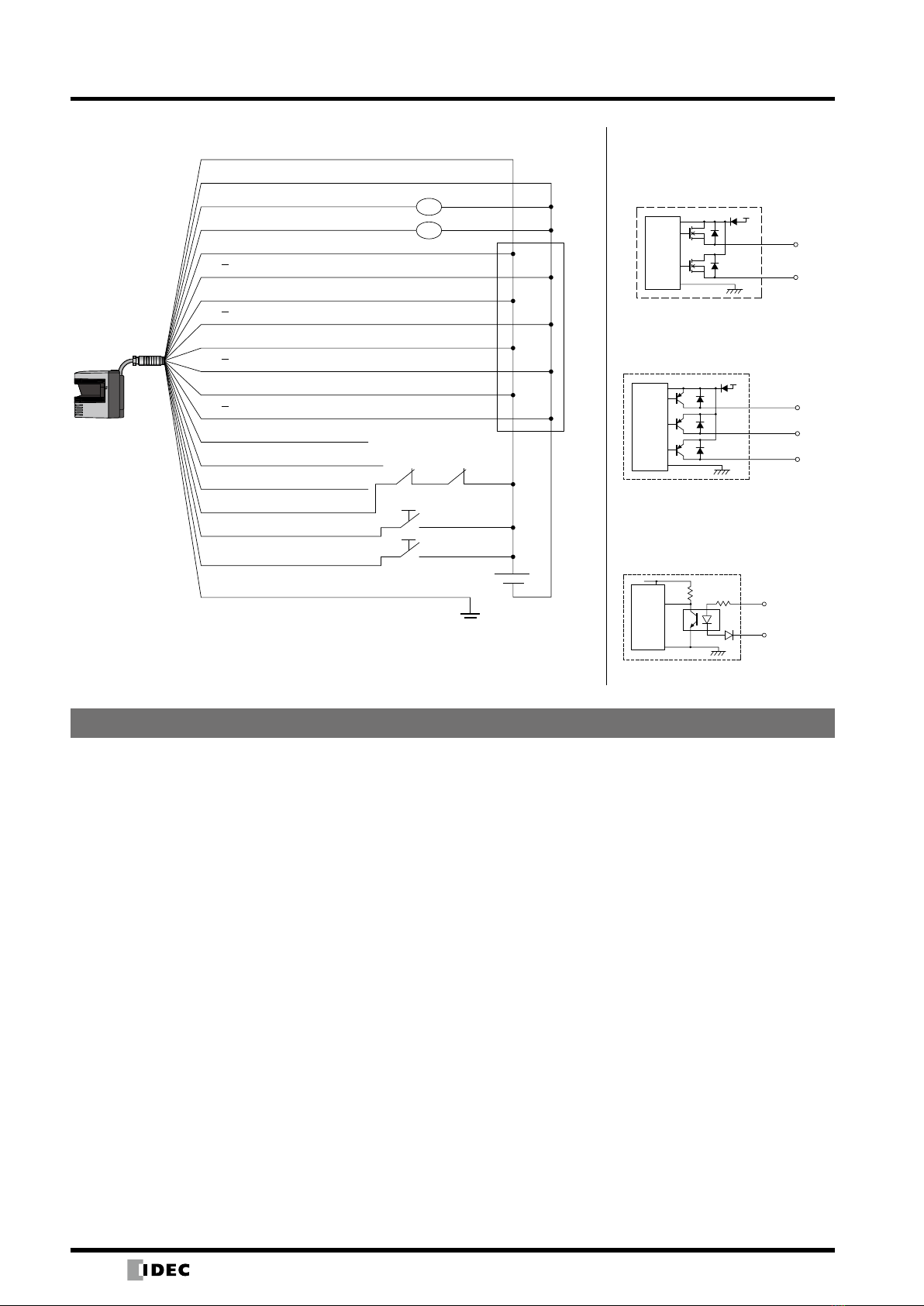
Input/Output Circuit
OSSD Output Circuit
OSSD outputs are N channel
MOSFET outputs.
OSSD1
OSSD2
Control
Circuit
+24V
Other Output Circuit
WARNING1, WARNING2, READY
outputs are PNP outputs.
WARNING1
WARNING2
Control
Circuit
+24V
READY
Input Circuit
Available for area input, EDM,
RESET, MUTING1, MUTING2, and
OVERRIDE.
Input
0V
Control
Circuit
Wiring Example
R1
R1 R2
S1
∗1
+24V DC (brown)
0V DC (blue)
OSSD1 (red)
OSSD2 (yellow)
IN_A (purple)
IN_A (purple/black)
IN_B (gray)
IN_B (gray/black)
IN_C (white)
IN_C (white/black)
IN_D/MUTING_1 (pink)
IN_D/MUTING_2 (pink/black)
WARNING1 (red/black)
WARNING2/ERR/MUT_OUT (yellow/black)
READY/RES_REQ (orange)
EDM (green)
RESET (green/black)
S2
OVERRIDE (orange/black)
FG (shielded wire)
R2
Safety Precautions
Wiring Example
(14/04/28)
19
SE1L Safety Laser Scanner
Safety Precautions
Installation
xInstall the SE1L on a stable surface or structure to
prevent displacement of the sensor.
xInstall the SE1L securely so that screws do not loosen
due to shock or vibration. (Recommended tightening
torque 3N∙m). Displacement may degrade protection
performance.
xDetermine the safety distance before installing the SE1L.
After installing the SE1L, use a test piece for all protection
zones to check the sensing functions. (Calculating safety
distance : see page 13)
xAfter installing the SE1L, to prevent entry into the
protective zone, use protective materials such as safety
guards and light curtains.
xThe reset switch to reset the interlock function should be
installed far from the protection zone.
xIf several SE1Ls are installed on the same sensing plane,
mutual interference may occur. For countermeasures on
mutual interference, see page 16.
xProvide enough space for installation and maintenance of
the SE1L.
xDo not cover the front of the optical window with glass or
transparent cover, otherwise detection characteristics of
the SE1L may be impaired.
xSE1L will not operate without initial configuration.
xMinimum sensing width differs according to the distance.
For details on performance specifications see page 6.
xThe stability of the SE1L increases by delaying the
response time of the OSSD signal but the sensing
performance decreases for moving objects. Before using
this function, be sure to carry out risk assessment.
Wiring
xBe sure to turn off all the power before wiring.
xWhen using converter power, make sure to use power
that satisfy the following requirements.
1) The rated output voltage is within 24V DC±10% (SELV
circuit, overvoltage category II)
2) The circuit between primary circuit and secondary
circuit is reinforced insulation or double insulation.
3) The output holding time is 20 ms.
4) The power supply must comply with electrical safety
and electromagnetic compatibility (EMC) regulations
requirements of each country, state, and district.
xAll input/output cables must be located away from power
cables and high voltage cables.
xTo control safety-related machine or system, use OSSD
output. Because warning zone output (warning signal) is a
non-safety signal, do not use for safety purposes.
xOnly use cables made for the SE1L. (For details see page
17.)
xUse an exclusive cable for connecting OSSD output wire
cable and safety-related machine or system.
Installation
xA password is used for configuring the safety function.
Only an administrator or operator should be able to use
the password.
xPerform test operation and check the configuration
before using the SE1L.
xThe operator must record the changes made in the
configuration. SLS Configurator report function is
available. For details, see the user’s manual.
Testing and Maintenance
xThe operator should perform the following tests or
maintenance based on the checklist.
1) Pre-operation inspection
2) Operation inspection
3) Daily inspection
4) Periodic inspection
This checklist is a basic guideline for performing
tests and maintenance. The operator should perform
additional tests and maintenance if necessary.
xStop the machine if failure occurs during tests.
xClean the optical window if any dirt is found, ask for
repair if damaged.
xDo not drop the SE1L. Otherwise damage or
failure may occur and performance cannot be
guaranteed. Also, injury may occur.
xSE1L cannot be sold, imported, or used in the Federal
Republic of Germany until December 2013.
Safety Precautions
(14/04/28)

IDEC CORPORATION (USA)
1175 Elko Drive, Sunnyvale, CA 94089-2209, USA
Tel: +1-408-747-0550 / (800) 262-IDEC (4332)
Fax: +1-408-744-9055 / (800) 635-6246
E-mail: [email protected]
IDEC CANADA LIMITED
3155 Pepper Mill Court, Unit 4
Mississauga, Ontario, L5L 4X7, Canada
Tel: +1-905-890-8561, Toll Free: (800) 262-IDEC (4332)
Fax: +1-905-890-8562
E-mail: [email protected]
IDEC AUSTRALIA PTY. LTD.
Unit 17, 104 Ferntree Gully Road,
Oakleigh, Victoria 3166, Australia
Tel: +61-3-8523-5900, Toll Free: 1800-68-4332
Fax: +61-3-8523-5999
E-mail: [email protected]
IDEC ELECTRONICS LIMITED
Unit 2, Beechwood, Chineham Business Park,
Basingstoke, Hampshire RG24 8WA, UK
Tel: +44-1256-321000, Fax: +44-1256-327755
E-mail: [email protected]
6-64, Nishi-Miyahara 2-Chome, Yodogawa-ku, Osaka 532-0004, Japan
Tel: +81-6-6398-2527, Fax: +81-6-6398-2547
E-mail: [email protected]
Specications and other descriptions in this brochure are subject to change without notice.
Cat. No. EP1444-1 APRIL 2014 PDF
IDEC ELEKTROTECHNIK GmbH
Wendenstrasse 331, 20537 Hamburg, Germany
Tel: +49-40-25 30 54 - 0, Fax: +49-40-25 30 54 - 24
E-mail: [email protected]
IDEC (SHANGHAI) CORPORATION
Room 701-702 Chong Hing Finance Center,
No. 288 Nanjing Road West, Shanghai 200003, PRC
Tel: +86-21-6135-1515
Fax: +86-21-6135-6225 / +86-21-6135-6226
E-mail: [email protected]
IDEC (BEIJING) CORPORATION
Room 211B, Tower B, The Grand Pacic Building,
8A Guanghua Road, Chaoyang District,
Beijing 100026, PRC
Tel: +86-10-6581-6131, Fax: +86-10-6581-5119
IDEC (SHENZHEN) CORPORATION
Unit AB-3B2, Tian Xiang Building, Tian’an Cyber Park,
Fu Tian District, Shenzhen, Guang Dong 518040, PRC
Tel: +86-755-8356-2977, Fax: +86-755-8356-2944
IDEC IZUMI (H.K.) CO., LTD.
Unit G & H, 26/F., MG Tower,
No. 133 Hoi Bun Road, Kwun Tong, Kowloon,
Hong Kong
Tel: +852-2803-8989, Fax: +852-2565-0171
E-mail: [email protected]
IDEC TAIWAN CORPORATION
8F-1, No. 79, Hsin Tai Wu Road, Sec. 1,
Hsi-Chih District, 22101 New Taipei City, Taiwan
Tel: +886-2-2698-3929, Fax: +886-2-2698-3931
E-mail: service@tw.idec.com
IDEC IZUMI ASIA PTE. LTD.
No. 31, Tannery Lane #05-01,
HB Centre 2, Singapore 347788
Tel: +65-6746-1155, Fax: +65-6844-5995
E-mail: [email protected]
IDEC ASIA (THAILAND) CO.,LTD.
20th Fl., Sorachai Bldg., No.23/78,
Soi Sukhumvit 63, Sukhumvit Rd.,
Klongton-nua, Wattana, Bangkok 10110
Tel: +662-392-9765, Fax: +662-392-9768
E-mail: [email protected]
www.idec.com
(14/04/28)
Table of contents
Other IDEC Safety Equipment manuals

Popular Safety Equipment manuals by other brands


Thiele
Thiele TWN 0868 Mounting instructions

schmersal
schmersal TV8S 521 operating instructions

SoftGuards
SoftGuards MNP09002 quick start guide

PDS
PDS WorkSafe AZ 700 Series instruction manual

3M
3M DBI SALA NANO-LOK 3101580 User instructions

Rescue Solutions International
Rescue Solutions International ResQmax Operation manual