IDEM SAFETY SWITCHES MPR User manual

Non Contact Magnetic Safety Switches
IMPORTANT NOTE:
Read and understand these instructions before installing operating or maintaining this equipment.
The product is designed to be a component of a customized safety oriented control system. It is the responsibility of the user to ensure the correct overall functionality of its systems and machines.
IDEM, its subsidiaries and affiliates, are not in a position to guarantee all of the characteristics of a given system or product not designed by IDEM.
APPLICATION:
Coded Non Contact s itches are designed to interlock hinged, sliding or removable guard doors. They are specifically advantageous hen:
a) poor guard alignment exists
b) high hygiene requirements exist e.g. food industry hose do n
c) a long mechanical life is required (no moving or touching parts).
When used in combination ith a Dual Channel Safety Relay or Control Device, Magnetic Non-Contact S itches can be used to provide protection up to Category 4 and PLe to ISO13849-1.
OPERATION:
All Magnetic Non-Contact Safety S itches are designed to conform to EN60947-5-3 and be used as directed by ISO14119 and EN ISO12100. They have magnetic sensing hich provides a ide
sensing distance and provides a high tolerance to misalignment after sensing. They can operate in extreme environments of temperature and moisture.
IMPORTANT:
The Risk Assessment for the particular application should include the risk of spare actuators. Spare actuators should not be readily available and must be securely controlled.
The safety functions and mechanics must be tested regularly. For applications ere infrequent guard access is foreseeable, the system must have a manual function test to detect a possible
accumulation of faults. At least once per month for PLe Cat3/4 or once per year for PLd Cat3 (ISO13849-1). Where possible it is recommended that the control system of the machine demands and
monitors these tests, and stops or prevents the machine from starting if the test is not done. (See ISO14119).
INSTALLATION:
Installation of all Non Contact S itches must be in accordance ith a risk assessment for the individual application.
Installation of the devices must be carried out by a competent person ith appropriate experience of machine control integration
The use of a Safety Relay or Control Device is recommended for monitoring magnetic s itches. These devices monitor 2 redundant circuits as per ISO13849-1 for up to PLe /Category 4 protection.
M4 mounting bolts must be used to fix the s itches. (Except RPR / RMR types, these types require fitting through 30.5mm clearance holes. The lock nuts supplied must be used to secure the
s itches). Tightening torque for mounting bolts to ensure reliable fixing is 1.0 Nm. Al ays mount on to Non Ferrous materials. The recommended setting gap is 5mm. The Safety s itch must not be
used as a mechanical stop or be adjusted by striking ith a hammer. The actuator must not be allo ed to strike the s itch. Do not mount adjacent s itches or actuators closer than 30mm.
Typical misalignment tolerance after setting is 5mm.
IMPORTANT: The NC switch contacts are potential free and are internally fused. To protect the internal fuse all switches must be externally fused at a lower rating (see Technical data).
After installation al ays check each s itch function by opening and closing each guard individually in turn and ensuring that the LED’s on the Safety Relay or Control Device are illuminated hen the
s itch is closed and are extinguished hen the s itch is open. Check that the machine stops and cannot be re-started hen each s itch is open.
For MPR types, fit the protective scre covers after the final checks have been completed.
ACTUATOR OPERATING DIRECTIONS
FOR OPTIMUM PERFORMANCE
:
Operating Instructions
MAINTENANCE:
Monthly: Check alignment of actuator and look for signs of mechanical damage to the s itch casing. Check iring for signs of damage.
Check each s itch function by opening and closing each guard individually in turn and ensuring that the appropriate LED’s on the Safety Relay are illuminated hen the s itch is closed and are
extinguished hen the s itch is open. Check that the machine stops and cannot be re-started hen each s itch is open.
Never repair any s itch, actuator or integral cables. Replace any s itch displaying signs of mechanical damage to the casing or cables.
These requirements form part of the product warranty.
MPR MMR-H SPR SMR SMR-F WPR WMR LPR LMR CPR CMR CMR-F
RPR RMR
SP
R
(PLASTIC)
SMR (S/STEEL)
SMR-F (S/STEEL)
SMR-H (S/STEEL)
WPR (PLASTIC)
WMR (S/STEEL)
MPR (PLASTIC)
MMR-H (S/STEEL)
LPR (PLASTIC)
LMR (S/STEEL)
CPR (PLASTIC)
CMR (S/STEEL)
CMR
-
F (S/STEEL)
RPR (PLASTIC)
RMR (S/STEEL)
WARNING: DO NOT DEFEAT TAMPER OR BYPASS THE SAFETY FUNCTION.
FAILURE TO DO SO CAN RESULT IN DEATH OR SERIOUS INJURY.
AVERTISSMENT: NE PAS DESACTIVER MODIFIER RETIRER OU CONTOURNER
CETI INTERVERROUILLAGE IL PEUT EN RESULTER DES
BLESSURES GRAVES DU PERSONNEL UTILISATEUR.
Original Instructions.
To request this data sheet in other languages please contact i[email protected]m
Um dieses Datenblatt in Deutscher Sprache enden Sie sich bitte anfordern info@idemsafety.com
Pour obtenir cette fiche en Français, veuillez contacter info@idemsafety.com
Para solicitar esta hoja de datos en Español, por favor contacto con info@idemsafety.com
Non Contact Magnetic Safety Switches
IDEM SAFETY SWITCHES Ltd. 2 Ormside Close Hindley Industrial Estate Hindley Green Wigan WN2 4HR UK.
Tel: +44 (0)1942 257070 Fax.: +44 (0)1942 257076
IDEM (USA) 4075 Papazian Way Suite 105 Fremont CA 94538 Tel:510-445-0751 Fax:1866-431-7064 email: sales@idemsafety.com Web: www.idemsafety.com
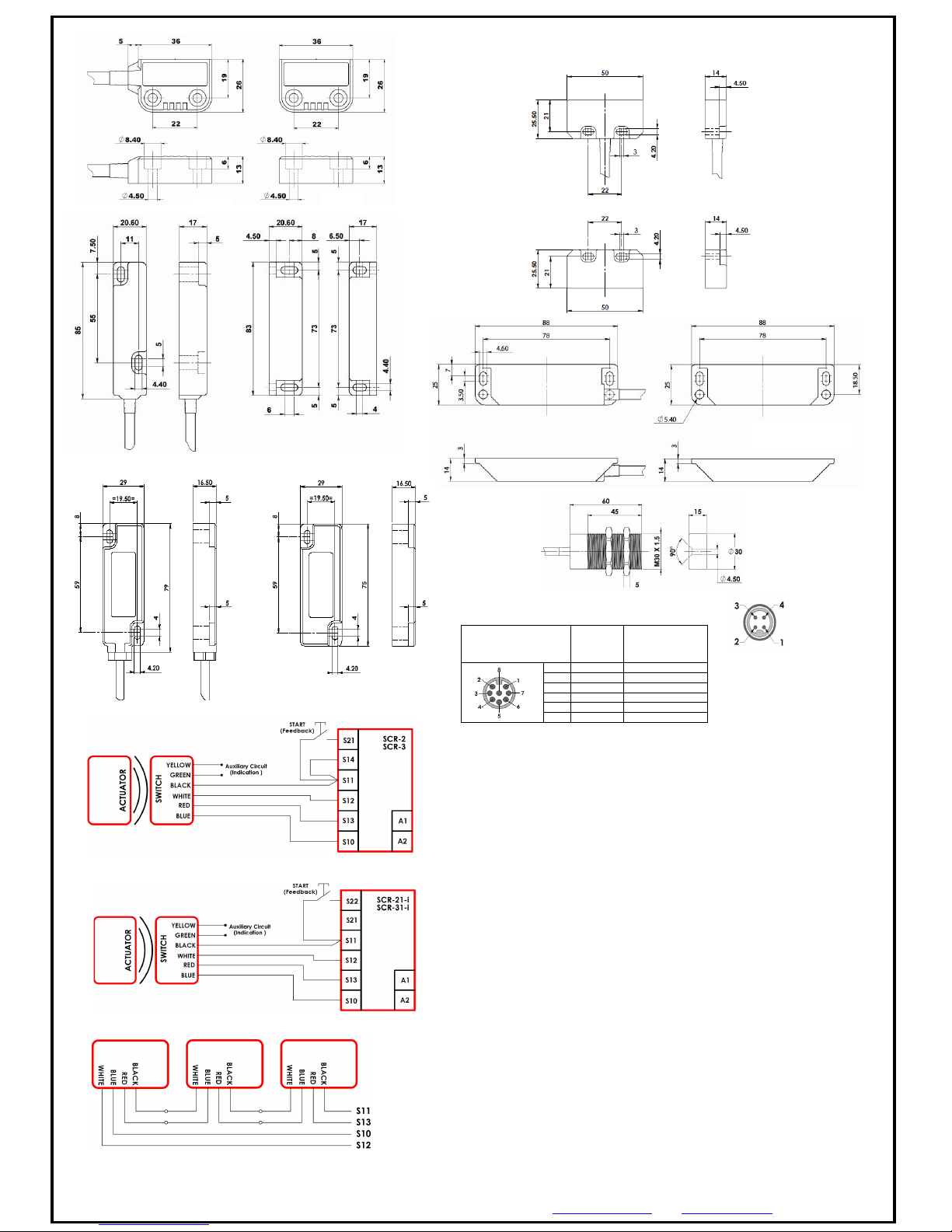
Quick Connect (QC)
M12 8 ay Male Plug (on
Flying Lead 250mm)
(Pin vie from s itch)
Flying Lead
Colours
Circuit
(Actuator present)
4
Yello
Auxiliary (NO)
6
Green
Auxiliary (NO)
7
Black
NC 2
1
White
NC 2
2
Red
NC 1
3
Blue
NC 1
Safety Classification and Reliability Data:
ISO 13849-1
B10d
Usage
Technical Data:
Standards:
Up to PLe Category 4
(if both channels are used ith a PLe control device)
3,300,000 cycles at 100mA load
8 cycles/hour 24 hours/365 days per year
MTTFd is 470 years
ISO14119 EN60947-5-3 EN60204-1 ISO13849-1 UL508
MPR MMR
-
H RPR RMR
Safety Circuits NC
SPR SMR LPR LMR CPR/CMR (2NC)
Safety Circuits NC
WPR WMR CPR/CMR (1NC)
Safety Circuits NC
Auxiliary Circuits NO
240V.ac / 24V.ac/dc 1.0 A. max.
(Fuse externally 0.5A. (F).
240V.ac / 24V.dc 1.0 A. max.
(Fuse externally 0.8A. (F).
240V.ac / 24V.dc 2.0 A. max.
(Fuse externally 1.6A. (F).
24V.ac/dc 0.2A. max.
Contact release time
<2ms
Initial contact re
sistance
<500 milliohm
Minimum s itched current
10V. dc 1mA
Delectric ithstand
250V.ac
Insulation Resistance
100 Mohms
Recommended setting gap
5mm
NC S itching Distance:
(Target to target)
NO S itching Distance
Sao 8mm
Sar 20mm
Opens before NC circuits close
Tolerance to misalignment
5mm in any direction from 5mm setting gap
S itching frequency
1.0 Hz maximum
Approach speed
200mm/m. to 1000mm/s.
Body Material
MPR SPR CPR LPR WPR RPR Polyester
SMR SMR-F SMR-H WMR CMR CMR-F RMR
MMR-H S/Steel 316
Temperature Range
-
25/80C. 105C. S/Steel for CIP/SIP cleaning
Enclosure Protection
Cable
I
P67 and IP69K
(QC versions IP67 for connector)
PVC 6.0mm OD Conductors 0.25 sq.mm
Mounting Bolts
2 x
M4 Tightening torque 1.0 Nm
CPR
CMR
CMR
-
F
LPR LMR
MPR
MMR
-
H
WPR WMR
Doc: 10250
4
Jun. 2018
Single switch to SCR
-
2
or SCR
-
3
Safety Relay
Single switch to SCR
-
21
-
I or SCR
-
31
-
I
Safety Relay
(Viper range)
Connecting in series to SCR range
RPR R
MR
CMR
-
F Rear Fixing Version
has t o x M4 x 10 tapped
holes at rear
.
MMR
-
H version has t o 5mm
through holes. Hexagon head
bolts can be used for ease of
cleaning.
For all s itches the NC
circuits are closed hen
the guard is closed and
the actuator is present.
SMC
-
F rear fixing version has
t o M4 x 10mm tapped holes at
the rear of housings.
SMC-H version has t o 5mm
through holes. Hexagon head
bolts can be used for ease of
cleaning.
SPR SMR
NC1 Pins 1 and 2
NC2 Pins 3 and 4
M12 4 Way Male Plug
(on Flying Lead 250mm)
Asi compatible pin out
(Pin vie from
S itch)
Information with r
egard to UL 508:
Type 1 Enclosures. Maximum temperature: 80ºC Plastic versions, 90ºC S/Steel versions.
Maximum output 24V.dc 200mA. Po ered by Class 2 or equivalent.
This manual suits for next models
14
Table of contents
Other IDEM SAFETY SWITCHES Switch manuals


Popular Switch manuals by other brands


StarTech.com
StarTech.com HB30C3A1CST quick start guide

HP
HP 316095-B21 - StorageWorks Edge Switch 2/24 release note

Grandstream Networks
Grandstream Networks GWN7701PA Quick installation guide

Hamlet
Hamlet XHUB4020AL user manual

BT
BT Business Hub 3 User guide and troubleshooting

Surecom
Surecom EP-824DX user manual


