Idis DirectCX TC-T5531WRX User manual

DirectCX
Camera
Installation Manual
TC-T5531WRX
TC-T5531WRXP
TC-T5532WRX

2
This is a basic installation manual for use of an IDIS camera. Users who are using this product for the rst time, as well
as users with experience using comparable products, must read this manual carefully before use and heed to the
warnings and precautions contained herein while using the product. Safety warnings and precautions contained in
this manual are intended to promote proper use of the product and thereby prevent accidents and property damage
and must be followed at all times. Once you have read this manual, keep it at an easily accessible location for future
reference.
•The manufacturer will not be held responsible for any product damage resulting from the use of unauthorized parts and
accessories or from the user's failure to comply with the instructions contained in this manual.
•The information in this document is believed to be accurate as of the date of publication even though explanation
about some functions may not be incorporated. The manufacturer is not responsible for any problems resulting from
the use thereof. The information contained herein is subject to change without notice. Revisions or new editions to this
publication may be issued to incorporate such changes.
•It is recommended that rst-time users of this camera and individuals who are not familiar with its use seek technical
assistance from their retailer regarding product installation and use.
•If you need to disassemble the product for functionality expansion or repair purposes, you must contact your retailer and
seek professional assistance.
•Both retailers and users should be aware that this product has been certied as being electromagnetically compatible for
commercial use. If you have sold or purchased this product unintentionally, please replace with a consumer version.
Safety Symbols
Symbol Publication Description
IEC60417, No.5031 Direct current
IEC60417, No.5032 Alternating current
In-Text
Symbol Type Description
Caution Important information concerning a specic function.
Note Useful information concerning a specic function.
Before reading this manual

Before reading this manual
3
Safety Precautions
WARNING
RISK OF ELECTRIC SHOCK
DO NOT OPEN
WARNING: TO REDUCE THE RISK OF ELECTRIC SHOCK,
DO NOT REMOVE COVER (OR BACK).
NO USER-SERVICEABLE PARTS INSIDE.
REFER SERVICING TO QUALIFIED SERVICE PERSONNEL.
Important Safeguards
1. Read Instructions
All the safety and operating instructions should be read before the
appliance is operated.
2. Retain Instructions
The safety and operating instructions should be retained for future
reference.
3. Cleaning
Unplug this equipment from the wall outlet before cleaning it. Do not
use liquid aerosol cleaners. Use a damp soft cloth for cleaning.
4. Attachments
Never add any attachments and/or equipment without the approval
of the manufacturer as such additions may result in the risk of re,
electric shock or other personal injury.
5. Water and/or Moisture
Do not use this equipment near water or in contact with water.
6. Placing and Accessories
Do not place this equipment on an wall or ceiling
that is not strong enough to sustain the camera. The
equipment may fall, causing serious injury to a child
or adult, and serious damage to the equipment. Wall
or shelf mounting should follow the manufacturer's
instructions, and should use a mounting kit approved
by the manufacturer.
This equipment and cart combination should be moved with care.
Quick stops, excessive force, and uneven surfaces may cause the
equipment and cart combination to overturn.
Do not place this equipment in an enclosed space. Sucient
ventilation is required to prevent an increase in ambient temperature
which can cause malfunction or the risk of re.
7. Power Sources
This equipment should be operated only from the type of power
source indicated on the marking label. If you are not sure of the
type of power, please consult your equipment dealer or local power
company.
You may want to install a UPS (Uninterruptible Power Supply)
system for safe operation in order to prevent damage caused by an
unexpected power stoppage. Any questions concerning UPS, consult
your UPS retailer.
This equipment should be remain readily operable.
8. Power Cord
Operator or installer must remove power and TNT connections before
handling the equipment.
9. Lightning
For added protection for this equipment during a lightning storm,
or when it is left unattended and unused for long periods of time,
unplug it from the wall outlet and disconnect the antenna or cable
system. This will prevent damage to the equipment due to lightning
and power-line surges. If thunder or lightning is common where the
equipment is installed, use a surge protection device.
10. Overloading
Do not overload wall outlets and extension cords as this can result in
the risk of re or electric shock.
11. Objects and Liquids
Never push objects of any kind through openings of this equipment
as they may touch dangerous voltage points or short out parts that
could result in a re or electric shock. Never spill liquid of any kind on
the equipment.
12. Servicing
Do not attempt to service this equipment yourself. Refer all servicing
to qualied service personnel.
13. Damage requiring Service
Unplug this equipment from the wall outlet and refer servicing to
qualied service personnel under the following conditions:
A. When the power-supply cord or the plug has been damaged.
B. If liquid is spilled, or objects have hit the equipment.
C. If the equipment has been exposed to rain or water.
D. If the equipment does not operate normally by following the
operating instructions, adjust only those controls that are covered
by the operating instructions as an improper adjustment of other
controls may result in damage and will often require extensive work
by a qualied technician to restore the equipment to its normal
operation.
E. If the equipment has been dropped, or the cabinet damaged.
F. When the equipment exhibits a distinct change in performance —
this indicates a need for service.
14. Replacement Parts
When replacement parts are required, be sure the service technician
has used replacement parts specied by the manufacturer or that
have the same characteristics as the original part. Unauthorized
substitutions may result in re, electric shock or other hazards.
15. Safety Check
Upon completion of any service or repairs to this equipment, ask the
service technician to perform safety checks to determine that the
equipment is in proper operating condition.
16. Field Installation
This installation should be made by a qualied service person and
should conform to all local codes.
17. Correct Batteries
Warning: Risk of explosion if battery is replaced by an incorrect type.
Replace only with the same or equivalent type.
Dispose of used batteries according to the instructions.
The battery shall not be exposed to excessive heat such as sunshine,
re or the like.
18. Tmra
A manufacturer’s maximum recommended ambient temperature
(Tmra) for the equipment must be specied so that the customer and
installer may determine a suitable maximum operating environment
for the equipment.

4
FCC Compliance Statement
THIS EQUIPMENT HAS BEEN TESTED AND FOUND TO COMPLY WITH THE LIMITS FOR A CLASS A DIGITAL DEVICE, PURSUANT TO PART
15 OF THE FCC RULES. THESE LIMITS ARE DESIGNED TO PROVIDE REASONABLE PROTECTION AGAINST HARMFUL INTERFERENCE
WHEN THE EQUIPMENT IS OPERATED IN A COMMERCIAL ENVIRONMENT. THIS EQUIPMENT GENERATES, USES, AND CAN RADIATE
RADIO FREQUENCY ENERGY AND IF NOT INSTALLED AND USED IN ACCORDANCE WITH THE INSTRUCTION MANUAL, MAY CAUSE
HARMFUL INTERFERENCE TO RADIO COMMUNICATIONS. OPERATION OF THIS EQUIPMENT IN A RESIDENTIAL AREA IS LIKELY TO
CAUSE HARMFUL INTERFERENCE, IN WHICH CASE USERS WILL BE REQUIRED TO CORRECT THE INTERFERENCE AT THEIR OWN EXPENSE.
WARNING: CHANGES OR MODIFICATIONS NOT EXPRESSLY APPROVED BY THE PARTY RESPONSIBLE FOR COMPLIANCE COULD VOID
THE USER’S AUTHORITY TO OPERATE THE EQUIPMENT. THIS CLASS OF DIGITAL APPARATUS MEETS ALL REQUIREMENTS OF THE
CANADIAN INTERFERENCE CAUSING EQUIPMENT REGULATIONS.
WEEE (Waste Electrical & Electronic Equipment)
Correct Disposal of This Product
(Applicable in the European Union and other European countries with separate collection systems)
This marking shown on the product or its literature, indicates that it should not be disposed with other household
wastes at the end of its working life. To prevent possible harm to the environment or human health from
uncontrolled waste disposal, please separate this from other types of wastes and recycle it responsibly to promote
the sustainable reuse of material resources.
Household users should contact either the retailer where they purchased this product, or their local government
oce, for details of where and how they can take this item for environmentally safe recycling.
Business users should contact their supplier and check the terms and conditions of the purchase contract. This
product should not be mixed with other commercial wastes for disposal.
Copyright
© 2020 IDIS Co., Ltd.
IDIS Co., Ltd. reserves all rights concerning this manual.
Use or duplication of this manual in part or whole without the prior consent of IDIS Co., Ltd. is strictly prohibited.
Contents of this manual are subject to change without prior notice for reasons such as functionality enhancements.
Registered Trademarks
IDIS is a registered trademark of IDIS Co., Ltd.
Other company and product names are registered trademarks of their respective owners.
The information in this manual is believed to be accurate as of the date of publication even though explanation
about some functions may not be incorporated. We are not responsible for any problems resulting from the use
thereof. The information contained herein is subject to change without notice. Revisions or new editions to this
publication may be issued to incorporate such changes.

5
Table of Contents
1
2
3
Part 1 – Introduction.........................................6
Product Features ................................................................6
Accessories. . . . . . . . . . . . . . . . . . . . . . . . . . . . . . . . . . . . . . . . . . . . . . . . . . . . . . . . . . . . . . . . . . . . . . 7
Overview .......................................................................8
Body......................................................................................8
I/O Device Port ............................................................................9
Installation .....................................................................10
Installation...............................................................................10
Angle Adjustment........................................................................10
Dimensions ..............................................................................11
Part 2 - Camera Connection .................................12
DirectCX DVR Layout ...........................................................12
Part 3 - Appendix ...........................................14
Troubleshooting ...............................................................14
Specications ..................................................................15

6
Product Features
TC-T5531WRX/TC-T5531WRXP/TC-T5532WRX is an
analog camera that tranmits video over coaxial.
•Supports DC 12V, AC 24V and PoC (Power over
Coaxial)
Power source for each model —see product
specications on the back page.
•TVI /AHD /SD video output support.
•Support for Smart IR
•Support fot Fog function
•Wide dynamic range compensation (True WDR) for
improved video quality in high-contrast situations
•Sense-up support for improved low-lighting video
capture performance
•Day & Night feature (built-in IR cut lter changer)
•Auto focus functionality
•Event detection modes: Motion Detection
•Includes a motorized focus and zoom auto IRIS lens
•IK10, IP67-level for water resistant protection and dust
proof against rain and dust
Part 1 – Introduction
Part 1 – Introduction
7
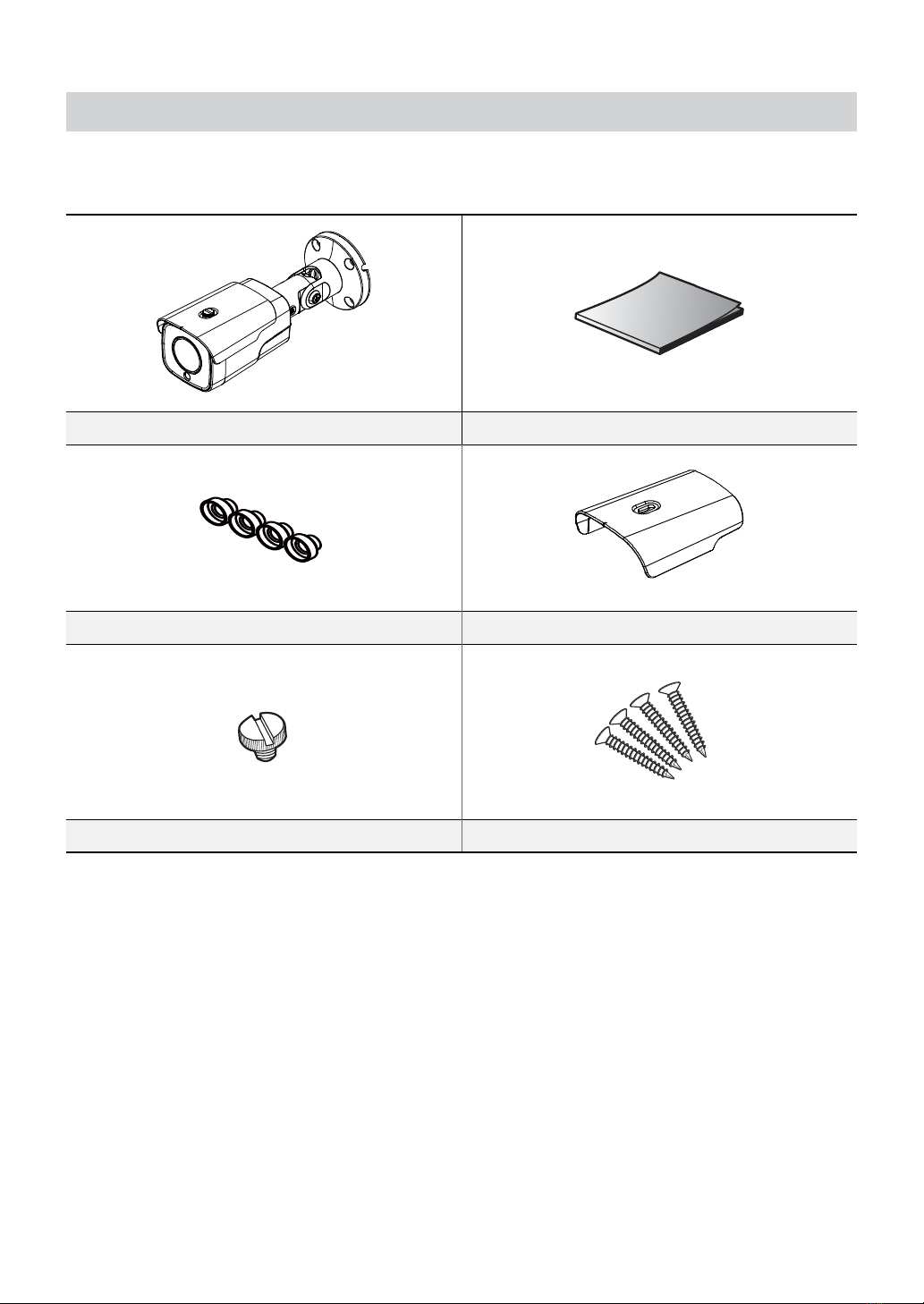
Accessories
Upon purchasing the product, check inside the box to make sure all the following accessories are included. External
appearances and colors of the accessories may vary depending on the model.
Camera Quick Guide
Bushings (4 ea.) Camera Sun Shield
Sun Shield Screw Screws (4 ea.)
Part 1 – Introduction
8
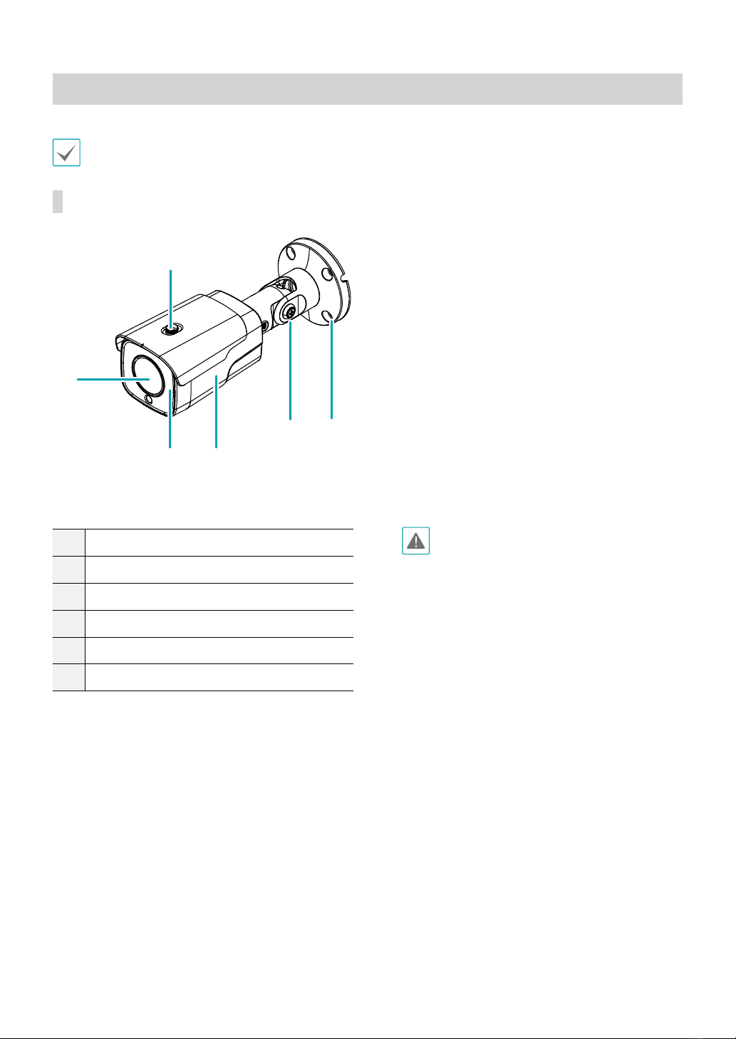
Overview
Product color and design may vary depending on the model.
Body
2 3
4
1
5
6
1Lens
2IR LED
3Body
4Stand
5Installation Bracket
6Sun Shield Screw Hole
•Lens
Motorized focus and zoom lens is installed.
•IR LED
A sensor in the bottom middle monitors lighting
levels and activates the IR LED during low-lighting
conditions.
•Body
The cables are connected through the stand.
•Stand
Allows you to adjust the camera direction and lens’
rotation angle.
•Installation Bracket
Install the camera to on the wall or ceiling.
•Sun Shield Screw Hole
Connect the screws to secure the camera sunshield
supplied with the product to the camera.
If the camera is not equipped with a
lens, protect the image sensor using the
protective cover provided with the camera.
Part 1 – Introduction
9
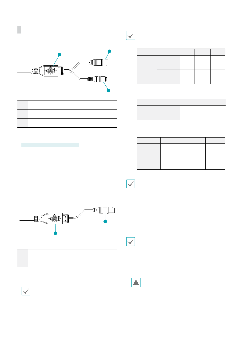
I/O Device Port
TC-T5531WRX / TC-T5532WRX
1
2
3
1Power In (DC 12V / AC 24V)
2BNC Video Out
3OSD Button
•Power In
Connect to the power adapter. (DC 12V / AC 24V)
AC 24V —TC-D5532RX/WRX only
•BNC Video Out
Connect to the DVR
•OSD Button
Use to set the OSD menu.
TC-T5531WRXP
1
2
1BNC Video Out (Black cable)
2OSD Button
•BNC Video Out
Connect to the PoC Power Unit.
For the TC-T5531WRXP, CVBS is available as a preview
only when the camera is being installed.
•OSD Button
Use to set the OSD menu.
The following table describes the DC 12V, AC 24V, and
coaxial cable specications.
<DC 12V cable specications>
Cable Type (AWG) #22 #20 #18
Maximum
length
TC-T5531
WRX/WRXP
20m 32m 52m
TC-T5532
WRX
16m 26m 41m
<AC 24V cable specications>
Cable Type (AWG) #22 #20 #18
Maximum
length
TC-T5532
WRX
60m 80m 100m
<The coaxial cable specifications>
Item Content Note
Conector
BNC
Cable
3C-2V 5C-2V
Maximum
Length
300m 500m
You can change the video output format by using the
OSD button.
•CVBS: Press the UP button three times, and
then press the center of the OSD button.
•TVI: Press the LEFT button three times, and
then press the center of the OSD button.
•AHD: Press the RIGHT button three times, and
then press the center of the OSD button.
You can change operate MFZ lens by using the OSD
button.
•ZOOM IN: Press the UP button.
•ZOOM OUT: Press the DOWN button.
•Focus NEAR: Press the LEFT button.
•Focus FAR: Press the RIGHT button.
Organize the power cable so that it will not cause
people to trip over or become damaged from
chairs, cabinets, desks, and other objects in the
vicinity. Do not run the power cable underneath
carpet or a rug or plug the cable into a power
outlet shared by a number of other devices.

Part 1 – Introduction
10
Installation
Installation of this product does not require the use of
special tools.
For more information on other devices comprising the
overall system, refer to their respective installation
manuals.
Product color and design may vary depending on the
model.
Installation
•Check the wall or ceiling to see if it needs to be
reinforced. The camera may fall o if the wall or
ceiling is not strong enough to support its weight.
•Install the camera in a shaded area. If the camera
is installed in direct sunlight, it may be aected
adversely.
1 Screw the camera sun shield to the camera using the
screw and rubber provided with the camera.
2 Screw the bottom cover to the wall or ceiling by
using screws(4) and bushings(4) provided with the
camera.
3 Band the stand to adjust the camera angle
accordingly. For details, refer to the angle
adjustment section.
4 Connect the external device and power adapter.
5 Apply Power.
Angle Adjustment
B
A
1
2
3
1Vertical (Tilt) Rotation
2Horizontal (Pan) Rotation
3Lens Rotation
•Vertical (Tilt) Rotation
After fully assembling the screw B, loosen the 2 to 2.5
wheels again and move the cover of the 2 joints on
the left side to slightly open. (However, make sure the
screws are not fully loosened so that it comes o ).
Once the camera has been oriented, turn the screws
clockwise to fully secure them.
•Horizontal (Pan) Rotation
After fully assembling the screw B, loosen the 2 to 2.5
wheels again and move the cover of the 2 joints on
the left side to slightly open. (However, make sure the
screws are not fully loosened so that it comes o ).
Once the camera has been oriented, turn the screws
clockwise to fully secure them.
•Lens Rotation
After fully assembling the screw A, loosen the 2 to 2.5
wheels again to orient the camera and turn the screw
clockwise to secure it fully.
Part 1 – Introduction
11
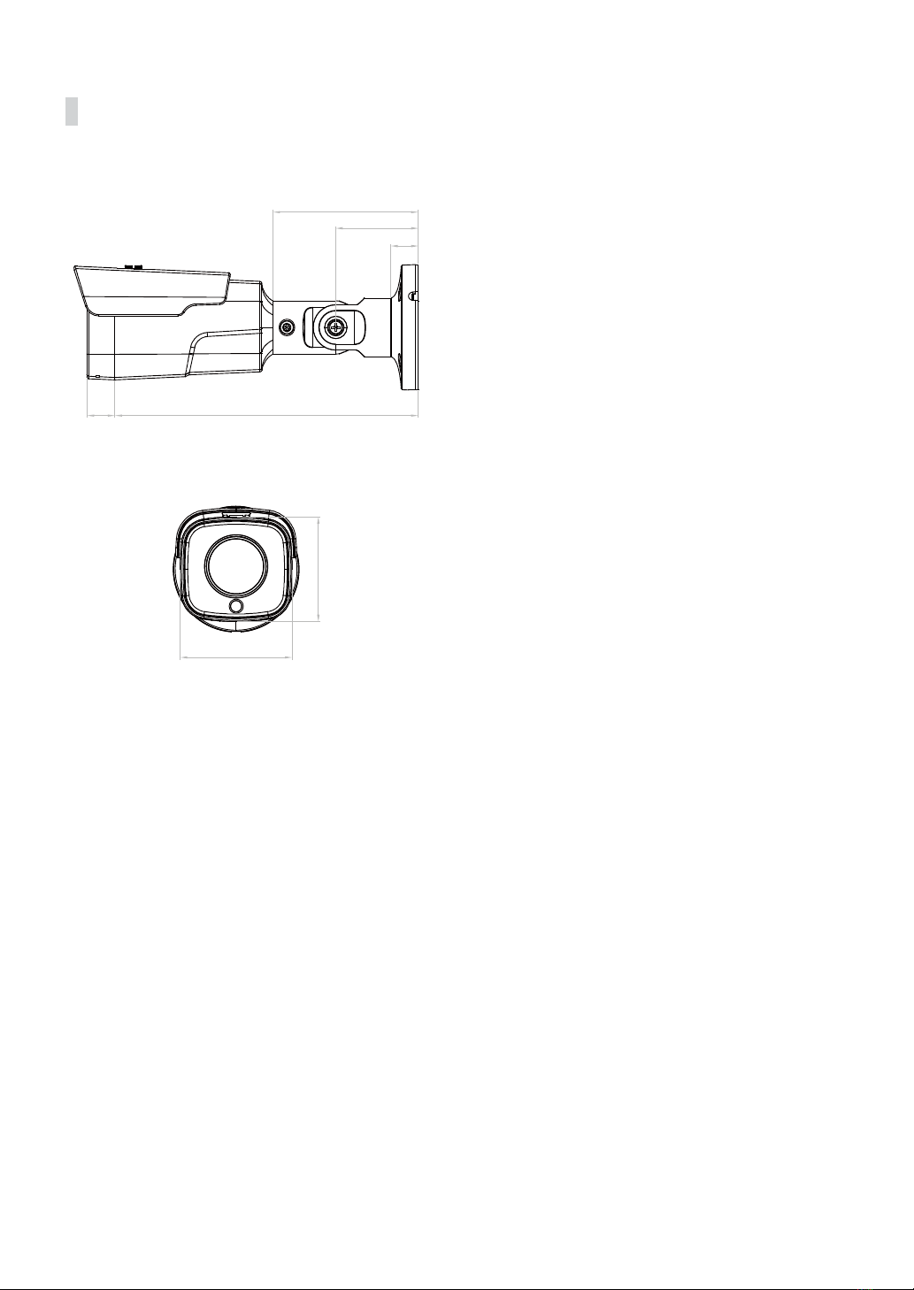
Dimensions
104mm
59mm
19.6mm
217mm
20mm
75mm
80mm

12
DirectCX DVR Layout
TC-T5531WRX
DirectCX DVR
TVI Camera
Power
iRAS Remote Monitoring
VGA Monitor Out
HDMI Monitor Out
Network
Part 2 - Camera Connection

Part 2 - Camera Connection
13
TC-T5531WRXP
DirectCX DVR
TVI Camera
Power
iRAS Remote Monitoring
VGA Monitor Out
HDMI Monitor Out
Network
PoC Power Unit

14
Troubleshooting
Problem Check
The main unit won't turn
on.
•Check the power cable connection. If using the PoC power, check the connection
of the coaxial cable.
•Check the power outlet. If using the PoC power, check the device power.
I can't see Live videos. •Check the camera's power status.
•Check the connection status of the DVR device.
•For using the Poc power, check the connection status of the PoC device.
Images are blurry. •Make sure the lens is clean. If not, clean it using a soft piece of cloth or a brush.
•Make sure the lens is in focus.
•If there is too much light coming into the camera or the camera is picking up an
overly bright light source, adjust the camera's position/angle accordingly.
Video color appears
incorrect.
Check the white balance settings. If using the Auto option, it may take some time
for the white balance to be adjusted.
Images are blinking. If the camera is pointed at the sun or a uorescent lamp, adjust the camera's angle
away.
Part 3 - Appendix

Part 3 - Appendix
15
Specications
These product specications may change without prior notice.
Camera
Image Sensor
1/2.8" CMOS
Max. Resolution
2592 x 1944
Scanning Mode
Progressive Scan
Lens type
Motorized Vari-focal
Focal Length
f=3 - 13.5mm
Aperture
F1.4 - 3.2
Iris Control
DC Iris
Angular Field of
View
5M (2592 x 1944)
H: 91° (Wide) ~ 31° (Tele)
V: 66° (Wide) ~ 23° (Tele)
D: 120° (Wide) ~ 38° (Tele)
4M (2560 x 1440)
H: 91° (Wide) ~ 31° (Tele)
V: 49° (Wide) ~ 17° (Tele)
D: 107° (Wide) ~ 35° (Tele)
Min. Illumination
COLOR : 0.13 lux F1.4
B/W : 0 lux (IR LED ON)
Dynamic Range
True WDR
Electronic Shutter Speed
Auto / Manual (1/30 ~ 1/30000), Anti-Flicker, Sense-up(OFF, X2, X4, X8, X16,
X32)
White Balance
Auto / Auto Expansion / AWC-SET / Manual
Day & Night
Auto / Manual
IR Distance (LEDs)
30m (4ea)

Part 3 - Appendix
16
General
Operating Temperature
-10°C ~ 55°C (-50°F ~ +131°F)
Operating Humidity
0% ~ 90%
Power Source TC-T5531WRX
DC 12V
TC-T5531WRXP
PoC
TC-T5532WRX
DC 12V, AC 24V
Power
Consumption
TC-T5531WRX
Max. 6.6W
TC-T5531WRXP
Max.7.4W
TC-T5532WRX
DC 12V Max. 8W
AC 24V Max. 8.3W
Approval
FCC, CE, IK10, IP67
No FCC CE certication for TC-5531WRXP
External Dimensions (Ø x H)
80mm X 75mm X 217mm (3.14" X 2.95"X 8.54 ")
Weight (Main
Unit)
TC-T5531WRX,
TC-T5532WRX
0.87kg (1.91lb)
TC-T5531WRXP
0.93kg (2.05lb)
Video
Video Output
TVI / AHD / SD
Max. Frame Rate
20fps : 2592 x 1944
12.5fps : 2592 x 1944
30fps : 2560 x 1440
30fps : 1920 x 1080
30fps : 720 x 480
Supported Resolution
2592 x 1944, 2560 x 1440, 1920 x 1080, 720 x 480
V1.2


IDIS Co., Ltd.
For more information, please visit at
www.idisglobal.com
This manual suits for next models
2
Table of contents
Other Idis Digital Camera manuals

Idis
Idis DC-B6203XL User manual

Idis
Idis TC-D5531RX User manual

Idis
Idis DirectCX TC-B5501X User manual

Idis
Idis DirectCX TC-B5501XP User manual

Idis
Idis DC-T6223HRL-A User manual

Idis
Idis TC-D5531RX User manual

Idis
Idis DirectCX TC-B5502X User manual

Idis
Idis DC-B1803 User manual

Idis
Idis DC-B3303X User manual

Idis
Idis DC-B Series User manual


