MULTIMEDIA
Installation Guide
2.4GHz Wireless Audio & Video Sender
TRANSVIDEO II
Ref. : TRA500
Les idées en plus…
www.idkmultimedia.com
CAUTION
RISK OF ELECTRIC SHOCK. DO NOT OPEN.
CAUTION: TO REDUCE THE RISK OF ELECTRIC SHOCK, DO NOT REMOVE COVER
(OR BACK). NOUSER-SERVICEABLE PARTS INSIDE. REFER SERVICING
TO QUALIFIED SERVICE PERSONNEL.
Explanation of two Symbols
The lightning flash with arrowhead symbol, within an equilateral triangle, is
intended to alert the user to the presence of uninsulated "dangerous voltage"
within the product's enclosure that may be of sufficient magnitude to constitute a
risk of electric shock to persons.
The exclamation point within an equilateral triangle is intended to alert the user to
the presence of important operating and maintenance-(servicing) instructions in
the literature accompanying the appliance.
THE GRAPHIC SYMBOLS WITH SUPPLEMENTAL MARKING ARE ON THE BOTTOM OF THE
SYSTEM.
WARNING:To prevent fire or shock hazard, do not expose this appliance to rain, water,
or wet locations. Do not insert any metallic object through the ventilation
grills.
Important-Safety Precautions
To prevent fire or shock hazard, do not expose this product to rain or moisture. Do not use near
a bathtub, washbowl, kitchen sink, or laundry tub, in a wet basement, or near a swimming pool.
To avoid electrical shock, do not open this product.
This product should be operated using only the power supply included with it or provided as an
accessory.
Do not overload wall outlets and extension cords as this can result in the risk of fire or electric
shock.
Refer servicing to qualified personnel only.
IMPORTANT SAFEGUARDS
All the safety and operating instructions should be read before the appliance is
operated and retained for future reference
1. HEED WARNINGS - All warnings on the appliance and in the operating instructions should be
adhered to.
2. FOLLOW INSTRUCTIONS - All operating instructions should be followed.
3. WATER AND MOISTURE - Do not use this video product near water - for example, a bathtub,
washbowl, kitchen sink, laundry tub or swimming pool, or in a wet basement.
4. POWER SOURCES - This product should be operated only from the type of power source
indicated on the marking label.
1
5. OVERLOADING - Do not overload outlets and extension cords, which can result in a risk of
fire or electric shock.
6. SERVICING - Do not attempt to service this product yourself. Opening or removing covers
may expose you to dangerous voltage or other hazards. Refer all servicing or repairs to
qualified service personnel.
7. DAMAGE REQUIRING SERVICE - Unplug this product from the wall outlet and refer servicing
or repairs to qualified service personnel under the following conditions:
a. When the power supply cord or plug is damaged.
b. If liquid has been spilled or objects have fallen into the product.
c. If the product has been exposed to rain or water.
d. If the product does not operate normally by following the operating instructions.
e. Adjust only those controls that are covered by the operating instructions.
f. If the product has been dropped or the cabinet has been damaged.
g. When the product exhibits a distinct change in performance.
8. REPLACEMENT PARTS - When replacement parts are required, be sure the service
technician has used replacement parts that are specified by the manufacturer or have the
same characteristics as the original part. Unauthorized substitutions may result in fire, electric
shock, or other hazards.
9. SAFETY CHECK - Upon completion of any service or repairs to this video product, ask the
service technician to perform safety checks to determine if the video product is in proper
operating condition.
10.An appliance and cart combination should be moved with care.
Do not place this equipment on an unstable cart, stand, or table. The equipment may fall,
causing serious injury to a child or adult, and serious damage to the equipment. Wall or shelf
mounting should follow the manufacturer's instructions and should be done with a mounting kit
approved by the manufacturer.
Note: This equipment has been tested and found to comply with the limits for CTC, FCC and CE
EMC directive. These limits are designed to provide reasonable protection against harmful
interference in a residential installation. This equipment generates, uses and can radiate
radio frequency energy and, if not installed and used in accordance with the instruction,
may cause harmful interference to radio communications. However, there is no guarantee
that interference will not occur in a particular installation. If this equipment does cause
harmful interference to radio or television reception, which can be determined by turning
the equipment off and on, the user is encourage to try to correct the interference by one or
more of the following measures:
Reorient or relocate the receiving antenna.
Increase the separation between the equipment and receiver.
Connect the equipment into an outlet on a circuit different from that to which the receiver is
connected.
Consult the dealer or an experienced radio/TV technician for help.
2
A. GENERAL DESCRIPTION
Congratulations on your purchase of the TRANSVIDEO II 2.4 GHz Wireless Audio & Video
Sender System. The TRANSVIDEO II lets you enjoy satellite TV, DVD, VCR, CDs and many
other audio/video media in another room - without purchasing additional components, moving
existing components or running cables. The 2.4 GHz Wireless Audio/Video Transmitter uses
wide-band FM to transmit true discrete stereo audio signals. The circular polarized high - gain
directional transmitting and receiving antennas minimize interference, resulting in maximum
clarity and a signal range of up to 300 feet (NTSC) 750 feet (PAL).
B. PACKAGE CONTENTS
Check to make sure that all of the items shown as below are included with your system. If
something is missing, please contact your dealer as soon as possible.
2.4GHz Wireless Transmitter x 1
2.4GHz Wireless Receiver x 1
IR Mouse x 1
230VAC to 9 VDC/300mA AC Power Adapters
(CE) x 2
RCA-to- LOOP SCART A/V Cable x 1
SCART-to-RCA A/V Cable x 1
3
C. PRODUCTS ILLUSTRATIONS
C-1 2.4GHz Wireless Audio & Video Transmitter TRANSVIDEO II
1 ON / OFF Power ON/OFF Switch
2Antenna High gain patch antenna sends audio and video
signals to the wireless receiver
3CHANNEL 1 2 3 4 Used to manually select channel settings 1-4
4IR JACK Connection for the IR extender accessory
5AUDIO LEFT RCA jacks for audio “L” input connector
6AUDIO RIGHT RCA jacks for audio “R” input connector.
7VIDEO RCA jacks for video input connector.
89V DC IN 9VDC Power input
9LED Power Indicator
10 IR LED IR Remote Receiver
4
C-2 2.4GHz Wireless Audio & Video Receiver
1 ON / OFF Power ON/OFF Switch
2Antenna High gain patch antenna receives audio and video
signals from the wireless transmitter
3CHANNEL 1 2 3 4 Used to manually select channel settings 1-4
4AUDIO LEFT RCA jacks for audio “L” output connector.
5AUDIO RIGHT RCA jacks for audio “R” output connector.
6VIDEO RCA jacks for video output connector.
79V DC IN 9VDC Power input
8IR SENSOR IR sensor to Receive the IR signal from the remote
controller
9IR LED IR Remote Transmitter
5
D. INSTALLATION
D-1 HOW TO CONNECT TRANSMITITTER SIGNAL FROM YOUR
VCR / SATELLITE / DVD
The power of Transmitter must be switched OFF prior to
proceeding the following steps.
Step 1.
Connect one end of the supplied A/V cables ( RCA-to- LOOP SCART) to the Audio/Video jacks
of the Transmitter; the other end to the Audio/Video Output jacks of the VCR/Satellite/DVD. Be
sure that the yellow, red and white plugs match the yellow, red and white jacks on both the
VCR/Satellite/DVD and the Transmitter.
Step 2.
Plug one end of the supplied AC Adapter (9VDC, 300 mA adapter) into the back of the
Transmitter, another end into any 230 volt (or 110 volt) wall outlet.. Use only the adapter
provided. The system is defaulted to channel 1. Turn the Transmitter on and ensure that the
Transmitter and Receiver are set to the same channels.
6
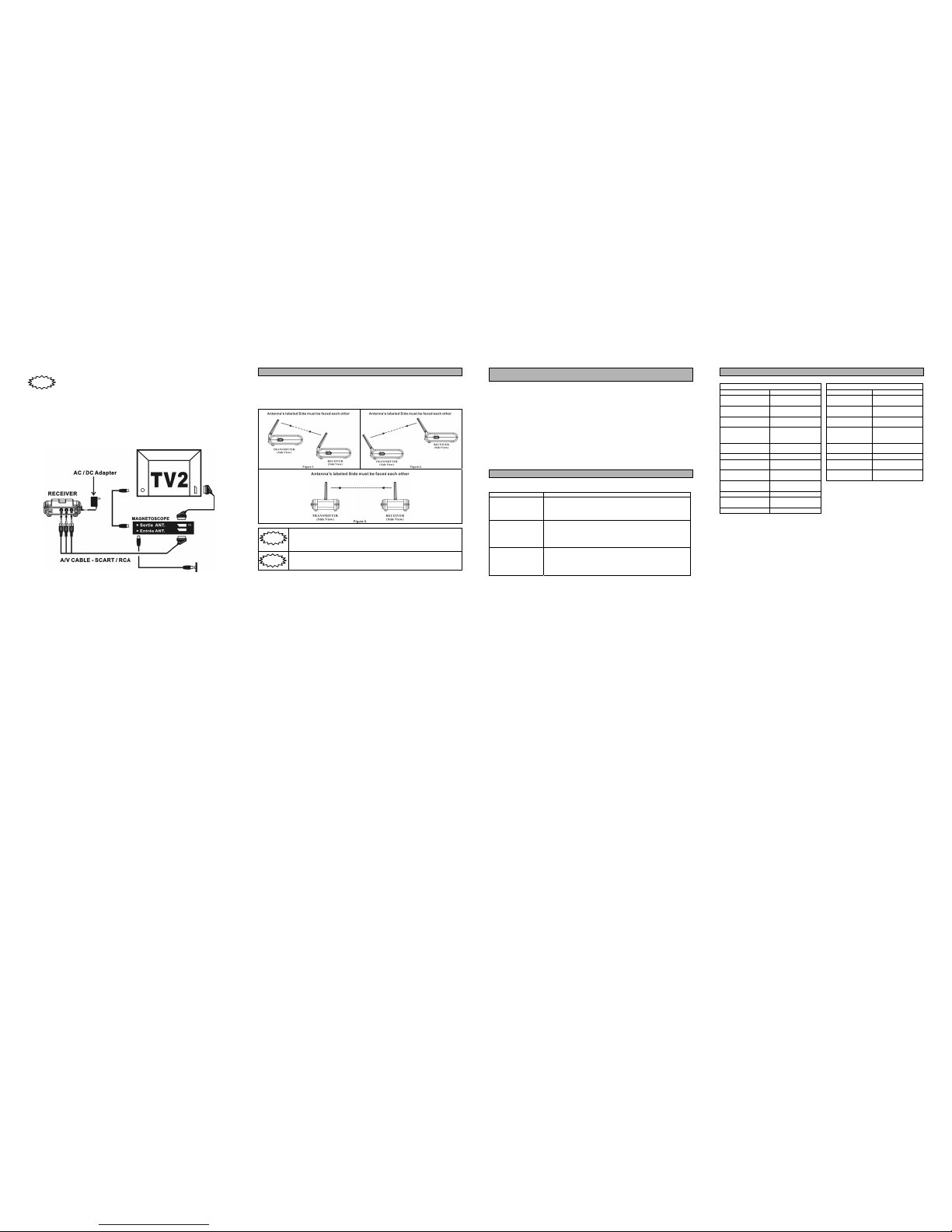
D-2 HOW TO CONNECT RECELVER TO A TV
The power of Receiver must be switched OFF prior to proceeding
the following steps.
Step 1.
Connect one end of the supplied A/V cables (RCA-to- LOOP SCART) to the Audio/Video jacks of
the Receiver; the other end to the Audio/Video Input jacks of the TV. Be sure that the yellow, red
and white plugs match the yellow, red and white jacks on both the TV and the Receiver. If the TV
has only a single jack for audio input, connect the white plug to that jack.
Step 2.
Plug one end of the supplied AC Adapter (9VDC, 300 mA adapter) into the back of the Receiver,
another end into any 230 volt (or 110 volt) wall outlet.. Use only the adapter provided.. The
system is defaulted to channel 1. Turn the Receiver on and ensure that the Receiver and
Transmitter are set to the same channels.
If your TV has picture-in-picture capabilities, you can view any image
transmitted by system, such as your sleeping baby, in a small inset
picture while enjoying other programming on the rest of the screen.
Consult the owner's manual of your TV for instructions on using these
capabilities.
7
c2
fgh