IDM-Energiesysteme TERRA 5 S/W H Guide

Aus
g
abe 15/09/1
1
THE POWER FAMILY
www.idm-energie.com
Heat pumps with freshwater technology
Technical documentation
Installation instructions
TERRA S/W BA (H) 05 - 45
for Brine and Ground Water Systems
with Navigator®1.0 Control
812216 Rev.7 - Translation of original instruction

THE POWER FAMILY
(C) IDM ENERGIESYSTEME GMBH
1
.
A
llgemei
n
e I
n
formatio
n
e
n
Installation TERRA S/W
2
1
2
3
4
5
6
7
8
9
1
0
1
1
1
2
1
3
Contents
Contents
1. GENERAL INFORMATION 4
1.2. General information 4
1.3. Safety Instructions 4
1.4. Transport 4
1.5. Sound Emission 4
1.6. Construction drying and screed heating 4
1.7. Servicing and Maintenance 4
1.8. Cleaning 4
1.9. Installing Additional Components 4
1.10. Installation Room 5
1.11. Protection of the environment 5
1.12. Standards and directives 5
2. DESCRIPTION 6
2.1. Description 6
2.2. Application range 6
2.3. Scope of delivery 6
2.4. Accessories 6
2.5. Dimensions 7
2.6. Technical data 8
2.7. Operating Limits 20
3. HEATING SIDE INSTALLATION 21
3.1. Installation 21
3.2. Installation Heating Side 25
4. ELECTRICAL INSTALLATION 26
4.1. Power supply 26
4.2. Connection Diagram Electrical Components 27
4.3. Disassembly Cover 28
4.4. Power Supply Connection 28
4.5. Heat Source Pump Connection 29
4.6. EMC 29
4.7. Layout of the Inputs on the Central Unit 30
4.7.1. Sensor design 31
4.7.2. Sensor equipment 31
4.7.3. Flow temperature sensor 31
4.8. Impulse inputs 31
4.9. Layout Outputs 33
4.9.1. Triac outputs (10 - 12): 33
4.9.2. Digital outputs 230V AC (20 - 38): 34
4.10. Connection of the mixers 35
4.11. System Earthing 35
4.12. Maximum restriction for underfloor heating: 35
4.13. Composite signal zone valves 35

THE POWER FAMILY
(C) IDM ENERGIESYSTEME GMBH Installation TERRA S/W 3
1
2
3
4
5
6
7
8
9
1
0
11
1
2
1
3
Contents
Contents
5. HEAT SOURCE 36
5.1. Brine Surfaces Collector 36
5.1.1. Description 36
5.1.2. Application range 36
5.1.3. Scope of delivery 36
5.2. Connection diagram 37
5.2.1. Laying diagram 38
5.3. Brine depth probe 38
5.3.1. Description 38
5.3.2. Application range 38
5.3.3. Scope of delivery 38
5.3.4. Installation diagram 39
5.4. Ground water use 40
5.4.1. Description 40
5.4.2. Application range 40
5.4.3. Installation diagram 41
5.4.4. Accessories 41
6. COMMISSIONING 42
6.1. Commissioning information 42
6.1.1. Selection of the Heat Source Pump 42
6.2. Operation 42
6.3. Faults 42
All rights reserved for modifications to the technology and design.

1
2
3
4
5
6
7
8
9
1
0
1
1
1
2
1
3
THE POWER FAMILY
(C) IDM ENERGIESYSTEME GMBH
G
e
n
eral i
n
formatio
n
Installation TERRA S/W
4
1
General information
1.2. General information
By purchasing this system you have acquired a
modern and efficient heating system. Ongoing qual-
ity controls and improvements as well as functional
checks at the plant guarantee you technically perfect
equipment.
Please read through this documentation carefully.
Itcontainsimportantinformationforcorrectinstallation
and safe and economical operation of the system.
1.3. Safety Instructions
Installation and maintenance work can be hazardous
due to high system pressure, high temperatures and
live parts and may only be operated by specialist
staff.
Heat pumps may only be installed by competent spe-
cialist staff and commissioned by a customer service
company trained to do so by IDM-Energiesysteme
GmbH.
When working on the heat pump, the system must be
deactivated and secured against reactivation.
In addition, all safety instructions in the relevant docu-
mentation,stickersontheheatpumpitselfandallother
applicable safety regulations must be observed.
1.4. Transport
During transport, the heat pump must never be
inclined more than 30°. The heat pump must not be
transported on the connection fittings. The transport
packaging may only be removed if the heat pump is
located at its installation location.
1.5. Sound Emission
TERRAheat pumps are very quiet in operation thanks
to their design. It is however important that the site of
the heater is situated as far as possible from noise-
sensitive living areas. A noise-insulating door should
be fitted door.
1.6. Construction drying and screed heating
The heat pump is not designed for the increased
heat requirements when drying out construction work
or heating plaster or screed. This must be covered
by equipment to be provided by the customer if re-
quired.
1.7. Servicing and Maintenance
Regular maintenance as well as checking and servic-
ing of all system components guarantee its safe and
economical operation in the long term. To achieve
this, we recommend a maintenance contract with the
relevant customer service company.
1.8. Cleaning
If necessary, the TERRA heat pump can be cleaned
with a damp cloth. The use of cleaning agents is not
recommended.
1.9. Installing Additional Components
The installation of additional components which
have not been tested with the equipment may impair
function. No liability is accepted and the guarantee
becomes void in the event of damage caused for this
reason.
1. General information
1
2
3
4
5
6
7
8
9
1
0
11
1
2
1
3
THE POWER FAMILY
(C) IDM ENERGIESYSTEME GMBH Installation TERRA S/W 5
1
General information
General information
1.10. Installation Room 1.11. Protection of the environment
1.12. Standards and directives
General instructions on operating the heat
pump.
Important instructions on assembling and
operating the heat pump. It is imperative
that these are observed.
General instructions on assembling the heat
pump.
Space for customer service
telephone number
Heatpumps are electrical equipment
made from high valuable materials,
which are not allowed to be disposed
like normal household garbage, but
have to be disposed professional and
proper according the regulations of the
local authorities.
A non-proper disposal can cause, apart
from sanctions for the violator, environ-
mental damages and harm for your
health.
-The TERRA heat pumps should be
installed in a frost-proof room. (Room
temperature should be between 5°C
and 35°C)
-In case of a floating floor screed the screed and
the sound damping around the heat pump have
to be omitted.
-Heat pumps should not be installed in wet rooms
or in potentially dust or explosion-endangered
rooms.
-Gas from refrigerants in plant rooms must not es-
cape into vicinal rooms, stair rooms, courtyards,
walks or into the drainage system of the building.
The gas has to be channelled off safely.
-In case of danger, the plant room has to be eva-
cuated immediately.
-For powering off the cooling facility, a remote
power-off switch has to be installed nearby the
door of the plant room.
-In case a natural ventilation is not possible, a
mechanical ventilation has to be provided. A
mechanical ventilation has to be equipped with
an independent emergency control outside of the
machine room near the door.
Note for the installation of the heatpump
follow all effective national and inter-
national piping- and installation rules
same as rules for accident prevention and
safety regulations when installing pipeline
systems and electrical components and
equipment as well as the instructions of
this Installation instruction.
Thereto belongs among other things:
- the general effective rules for accident prevention
and safety regulations
- the regulations for environmental protection
- the provisions/regulations of the professional asso-
ciations.
- the effective laws, standards, guidelines and regu-
lations e.g. DIN,EN,DVGW,VDI and VDE
- regulations of the local suppliers/supply companies
THE POWER FAMILY
(C) IDM ENERGIESYSTEME GMBH
2
.
A
llgemei
n
e I
n
formatio
n
e
n
Installation TERRA S/W
6
1
2
3
4
5
6
7
8
9
1
0
1
1
1
2
1
3
1
2
Description
2. Description
2.1. Description
Heat pump with suction gas cooled scroll compressor
with generously sized stainless steel heat exchangers
as evaporator and condenser built on a robust frame
and fitted with a heat and soundproof casing.
The heat pump also contains an electrical panel with
the Navigator Control and with all the switching and
safety mechanisms built-in.
The heat pump has a compact design, the evaporator
is already fitted in the heat pump housing. The heat
pump is filled with refrigerant and checked to ensure
it functions correctly. It is suitable for brine circuit sur-
face collectors, brine circuit deep boreholes, as well
as for ground water use.
2.2. Application range
For the monovalent heating of detached and semi-
detached houses with geothermal heat utilisation.
When doing so the house should be fitted with a low
temperature heating system (e.g. underfloor heating,
wall heating, low temperature radiator heating).
TERRA heat pumps work with the safety refrigerants
R 407 C or R 134 A which, when properly installed
and commissioned, circulate in a closed circuit and
therefore have virtually no environmental impact.
2.3. Scope of delivery
- Heat pump unit with suction gas cooled scroll com-
pressor
- Stainless steel plate heat exchanger as condenser
- Stainless steel plate heat exchanger as evaporator
- Refrigerant collector and dryer
- Thermostatic expansion valve
- Refrigerant inspection glass
- Refrigerant heat exchanger
- High pressure and low-pressure limiter
- Electrical panel with Navigator Control
- Stable base frame
- Cladding, insulated against heat and noise
-4flexible connection hoses
- Start-up current limiter for compressor
2.4. Accessories
- Brine surface collector made of plastic piping Ø 25
x 2.3 mm in rings for each 100 m, incl. distributors
and connection material and brine circuit pump
- Expansion set for 2 additional mixer circuits
- Charging pump assembly with pump 2 shut-off
valves and pump beater
- Safety heat exchanger (Groundwater heat pumps)
Thelower themaximum flowtemperature
is set, the higher the efficiency of the heat
pump.
The respective charging pumps are not
included in the scope of delivery. These
can be ordered as accessories.
THE POWER FAMILY
(C) IDM ENERGIESYSTEME GMBH Installation TERRA S/W 7
1
2
3
4
5
6
7
8
9
1
0
11
1
2
1
3
1
2
7
762
B
A
2
1
3
2
1
3
C
D
F
E
G
6
7
4
5
6
7
4
5
Vorderseite Linke Seite Rückseite
210
725
145 230
1
2
3
4
5
8
7
6
Wärmepumpe
MM
620 1100
1200
70
300
210
725
1
3
4
5
2
7
6
Description
Description
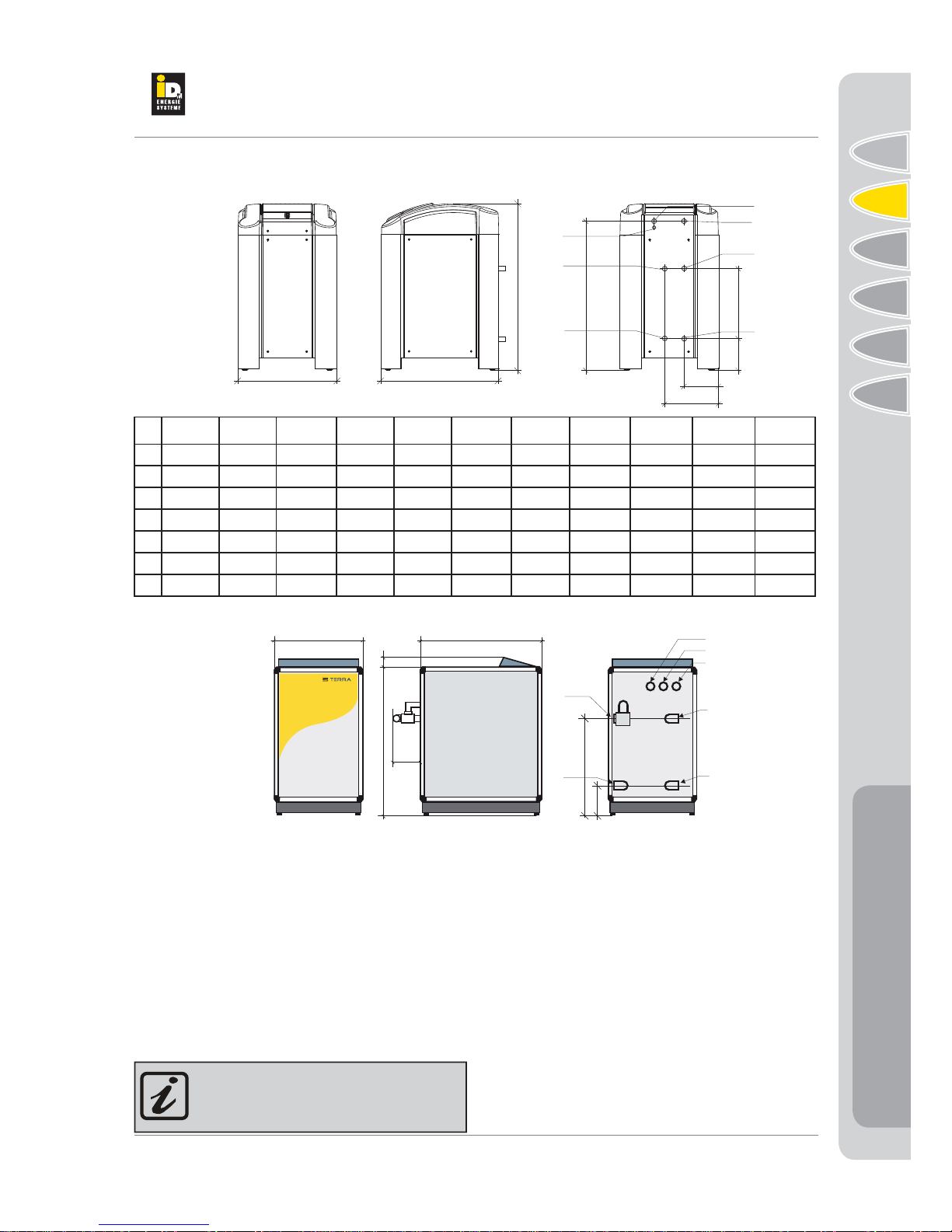
2.5. Dimensions
5 S/W 7 S/W 8 S/W 10S/W 12S/W 15S/W 17S/W 19S/W 22S/W 26S/W 30S/W
A622 622 622 622 622 622 622 622 750 750 750
B1160 1160 1160 1160 1160 1160 1160 1160 1160 1160 1160
C1025 1025 1025 1025 1025 1025 1025 1025 1025 1025 1025
D466 466 466 466 466 466 466 466 457 457 457
E220 220 220 220 220 220 220 220 210 210 210
F190 190 190 190 190 190 190 190 264 264 264
G322 322 322 322 322 322 322 322 469 469 469
Key:
1 Heat pump flow connection (please use enclosed connection hose)
2 Opening for main current connection
3 Heat pump return connection (please use enclosed connection hose)
4 Brine inlet (please use enclosed connection hose)
5 Brine outlet (please use enclosed connection hose)
6 Opening for ground water pump control
7 Opening for low voltage cable (sensor and data lines)
Dimensions of the connections: see technical data on the following pages.
On the rear of the heat pump there is
a sticker with the description of the con-
nection.
SW 05-30:
SW 37-45:
THE POWER FAMILY
(C) IDM ENERGIESYSTEME GMBH
2
.
A
llgemei
n
e I
n
formatio
n
e
n
Installation TERRA S/W
8
1
2
3
4
5
6
7
8
9
1
0
1
1
1
2
1
3
1
2
Description
Description
Technical Data TERRA S/W with R407C
Type TERRA (BA) (HGL) Unit 5 S/W 7 S/W 8 S/W 10 S/W 12 S/W
Dimensions (H x W x D) cm 116/62/76 116/62/76 116/62/76 116/62/76 116/62/76
Weight HGL/Basic kg 130/116 136/122 144/130 150/136 156/140
Electrical connection of the primary circuit V/Hz 3x400 / 50 3x400 / 50 3x400 / 50 3x400 / 50 3x400 / 50
Power consumption compressor A 4.2 5.1 6.3 7 10
Start-up current compressor (with soft start) A 10.5 12.75 15.75 17.5 25
Electrical connection control circuit V/Hz 230 / 50 230 / 50 230 / 50 230 / 50 230 / 50
Fuse control circuit A 13 13 13 13 13
Refrigerant R 407 C R 407 C R 407 C R 407 C R 407 C
Filling volume kg 1.8 2.05 2.2 2.5 2.6
Filling volume compressor oil l 1 1 1.1 1.1 1.36
Minimum size installation room m³ 5.8 6.1 6.5 6.8 8.4
Minimum size ventilation opening (natural) m² 0.19 0.19 0.20 0.20 0.23
Minimum air flow (mechanical) m³/h 75 77 80 83 95
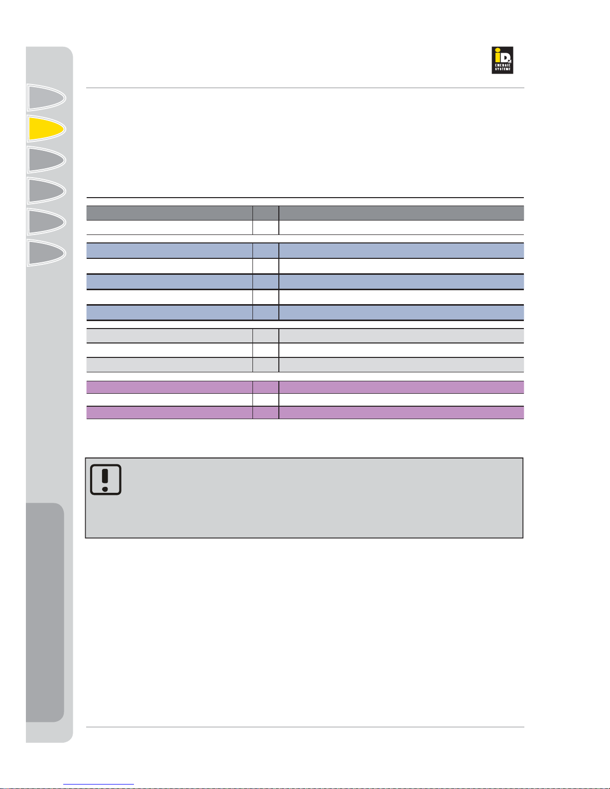
2.6. Technical data
For the dimensioning of the fuse to be connected in series in the primary circuit, the nominal
current of the compressor and the on-site heat source pump as well as, if available, of the inter-
mediate circuit pump must be added.
Recommended power protection switch types: 3-pole Type C, K

THE POWER FAMILY
(C) IDM ENERGIESYSTEME GMBH Installation TERRA S/W 9
1
2
3
4
5
6
7
8
9
1
0
11
1
2
1
3
1
2
Description
Description
15 S/W 17 S/W 19 S/W 22 S/W 26 S/W 30 S/W 37 S/W 45 S/W
116/62/76 116/62/76 116/62/76 126/75/76 126/75/76 126/75/76 130/62/110 130/62/110
164/148 172/154 178/160 248/230 262/244 268/250 320/300 342/322
3x400 / 50 3x400 / 50 3x400 / 50 3x400 / 50 3x400 / 50 3x400 / 50 3x400 / 50 3x400 / 50
11 13 15 15.9 16.8 19.6 28 34
27.5 32.5 37.5 39.8 42 49 70 85
230 / 50 230 / 50 230 / 50 230 / 50 230 / 50 230 / 50 230 / 50 230 / 50
13 13 13 13 13 13 13 13
R 407 C R 407 C R 407 C R 407 C R 407 C R 407 C R 407 C R 407 C
2.9 3.2 3.4 3.95 8.4 9.4 10.5 10.8
1.85 1.65 1.65 4.1 4.1 4.1 4.1 4.1
9.4 10,0 11.0 12.3 26.5 30.0 33.9 34.8
0.24 0.25 0.26 0.27 0.40 0.43 0.45 0.46
102 107 114 123 205 223 242 246

THE POWER FAMILY
(C) IDM ENERGIESYSTEME GMBH
2
.
A
llgemei
n
e I
n
formatio
n
e
n
Installation TERRA S/W
10
1
2
3
4
5
6
7
8
9
1
0
1
1
1
2
1
3
1
2
Description
Description
Technical Data TERRA S/W for Brine Application with R407C
Type TERRA (BA) (HGL) Unit 5 S/W 7 S/W 8 S/W 10 S/W 12 S/W
Heating performance for S0°C/W35°C EN 255 kW 5.4 6.8 8.3 9.7 12.0
Heating performance for A2°C/W35°C kW 5.37 6.76 8.25 9.64 11.93
Power consumption for S0°C/W35°C EN 255 kW 1.23 1.55 1.80 2.10 2.59
Power consumption for S0°C/W35°C kW 1.29 1.63 1.89 2.20 2.72
COP for S0°C/W35°C EN 255 4.40 4.40 4.60 4.62 4.63
COP for S0°C/W35°C 4.15 4.15 4.37 4.38 4.38
Radiator flow and return pipe P [O.T.] 1" 1" 1" 1" 1"
HGL connection P [O.T.] 1" 1" 1" 1" 1"
Max. flow temperature °C 55 55 55 55 55
Min. heating circuit water volume l/h 900 1100 1.400 1600 2.000
Pressure loss, heating side kPa 9 12 12 16 14
Recommended or installed storage tank
charging (Grundfos/ Wilo) UPS 25-60
EAS 25/6 UPS 25-60
EAS 25/6 UPS 25-60
EAS 25/6 UPS 25-60
EAS 25/6 UPS 25-60
EAS 25/6
Free residual pressure of the charging pump kPa 40 36 32 26 24
In heat pumps with process reversal
Cooling performance for W/B 15°C/8W°C kW 4.60 6.00 7.10 8.35 10.35
Cooling performance for W/B 15°C/18W°C kW 6.45 8.40 9.95 11.70 14.45
Power consumption for W/B15°C/8°C kW 0.96 1.23 1.44 1.70 2.10
Power consumption for W/B15°C/18°C kW 0.96 1.23 1.44 1.70 2.05
ERR at W/B 15°C/W8°C 4.79 4.88 4.93 4.91 4.93
Brine inlet and outlet P [O.T.] 1" 1" 1" 1" 1"
Minimum brine circulation volume kg/h 1050 1300 1600 1900 2350
Pressure loss on the brine side kPa 7 10 14 12 14
Recommended brine circuit pump Wilo
Top S 25/7 Wilo
Top S 25/7 Wilo
Top S 25/7 Wilo
Top S 25/7 Wilo
Top S 25/7
Dimension of the connection lines up to 40 m
total length mm 32 x 2.0 32 x 2.0 40 x 2.3 40 x 2.3 40 x 2.3
Number of brine circuits 3 3 4 5 6
Total pipe length m 300 300 400 500 600
Brine filling volume (mix) l 105 105 140 175 210
Depth probe 1/80 1/100 2/130 2/150 2/190
Number of depth probes 1 1 2 2 2
Total probe length m 80 100 130 150 190
Filling volume brine mix (1 x 40 mm probe) l 140 175 225 260 325
Filling volume brine mix (2 x 32 mm probe) l 175 220 285 325 410
Sound power level dBA 53 53 55 55 55
*Reference values for 50 W/m extraction performance

THE POWER FAMILY
(C) IDM ENERGIESYSTEME GMBH Installation TERRA S/W 11
1
2
3
4
5
6
7
8
9
1
0
11
1
2
1
3
1
2
Description
Description
15 S/W 17 S/W 19 S/W 22 S/W 26 S/W 30 S/W 37 S/W 45 S/W
14.9 17.2 19.6 22.1 24.2 27.9 34.8 41.8
14.81 17.10 19.48 21.97 24.15 27.84 34.73 41.72
3.16 3.64 4.10 4.77 5.23 6.04 8.25 9.88
3.34 3.86 4.41 5.02 5.51 6.49 8.66 10.38
4.72 4.73 4.71 4.63 4.63 4.62 4.22 4.23
4.43 4.43 4.42 4.38 4.38 4.29 4.01 4.02
1" 1 1/4" 1 1/4" 1 1/2" 1 1/2" 1 1/2" 2" 2"
1" 1" 1" 1" 1 1/4" 1 1/4" 1 1/4" 1 1/4"
55 55 55 55 55 55 55 55
2.400 2.700 3.100 3600 4.300 5.000 6000 7.400
21 17 17 15 22 22 18 21
UPS 25-80 UPS 25-80 UPS 25-80 UPS 25-80
Top S 30/7 UPS 25-80
Top S 30/7 TOP S 30/10 TOP S 40/10 TOP S 40/10
44 44 42 40 28 60 74 67
12.65 15.40 17.10 19.30 23.30 27.00 33.50 40.50
18.00 21.40 23.90 27.20 32.50 37.50 46.00 56.00
2.58 2.99 3.33 3.91 4.65 5.25 6.70 8.00
2.76 3.12 3.52 4.20 4.70 5.35 7.10 8.90
4.90 5.15 5.14 4.94 5.01 5.14 5.00 5.06
1" 1 1/4" 1 1/4" 1 1/2" 1 1/2" 1 1/2" 2" 2"
2900 3.400 3.850 4.300 5150 5.900 7.200 8.800
13 16 16 16 20 20 20 21
Grundfos
UPS 25-80 Grundfos
UPS 32-80 Grundfos
UPS 32-80 Grundfos
UPS 32-80 Wilo
TOP S 40/10 Wilo
TOP S 40/10 Wilo
TOP S 50/10 Wilo
TOP S 50/10
50 x 2.9 50 x 2.9 50 x 2.9 50 x 2.9 63 x 3.6 63 x 3.6 63 x 3.6 75 x 4.3
7 7 8 9 11 13 15 18
700 700 800 900 1100 1300 1500 1800
245 245 280 315 385 455 525 630
3/225 3/270 3/300 4/340 4/400 5/475 6/570 7/700
33344567
225 270 300 340 400 475 570 700
350 460 510 580 680 810 970 1180
485 580 645 730 860 1020 1220 1500
56 57 57 59 61 61 63 65

THE POWER FAMILY
(C) IDM ENERGIESYSTEME GMBH
2
.
A
llgemei
n
e I
n
formatio
n
e
n
Installation TERRA S/W
12
1
2
3
4
5
6
7
8
9
1
0
1
1
1
2
1
3
1
2
Description
Description
Technical Data TERRA S/W H with R134A
Type TERRA (BA) (HGL) Unit 5 S/W H 7 S/W H 8 S/W H 10 S/W H 12 S/W H
Dimensions (H x W x D) cm 116/62/76 116/62/76 116/62/76 116/62/76 116/62/76
Weight HGL/Basic kg 130/116 136/122 144/130 150/136 156/140
Electrical connection of the primary circuit V/Hz 3x400 / 50 3x400 / 50 3x400 / 50 3x400 / 50 3x400 / 50
Power consumption compressor A 3,59 4,48 5,3 6,06 7,34
Start-up current compressor (with soft start) A 10.5 12.75 15.75 17.5 25
Electrical connection control circuit V/Hz 230 / 50 230 / 50 230 / 50 230 / 50 230 / 50
Fuse control circuit A 13 13 13 13 13
Refrigerant R 134A R 134A R 134A R 134A R 134A
Filling volume kg 1.6 1.8 1.9 2 2.4
Filling volume compressor oil l 1 1 1.1 1.1 1.36
Minimum size installation room m³ 6.4 7.2 7.6 8 9.6
Minimum size ventilation opening (natural) m² 0.18 0.19 0.19 0.20 0.22
Minimum air flow (mechanical) m³/h 69 75 77 80 90
For the dimensioning of the fuse to be connected in series in the primary circuit, the nominal
current of the compressor and the on-site heat source pump as well as, if available, of the inter-
mediate circuit pump must be added.
Recommended power protection switch types: 3-pole Type C, K
THE POWER FAMILY
(C) IDM ENERGIESYSTEME GMBH Installation TERRA S/W 13
1
2
3
4
5
6
7
8
9
1
0
11
1
2
1
3
1
2
Description
Description
15 S/W H 17 S/W H 19 S/W H 22 S/W H 26 S/W H 230 S/W H 37 S/W H 45 S/W H
116/62/76 116/62/76 116/62/76 126/75/76 126/75/76 126/75/76 130/62/110 130/62/110
164/148 172/154 178/160 248/230 262/244 268/250 320/300 342/322
3x400 / 50 3x400 / 50 3x400 / 50 3x400 / 50 3x400 / 50 3x400 / 50 3x400 / 50 3x400 / 50
8,59 10,04 11,56 13,03 14,06 15,94 23,09 28,71
27.5 32.5 37.5 39.8 42 49 70 85
230 / 50 230 / 50 230 / 50 230 / 50 230 / 50 230 / 50 230 / 50 230 / 50
13 13 13 13 13 13 13 13
R 134 A R 134 A R 134 A R 134 A R 134 A R 134 A R 134 A R 134 A
2.7 2.9 3.1 4.1 7.7 8.9 10.6 10.9
1.85 1.65 1.65 4.1 4.1 4.1 4.1 4.1
10.8 11.6 12.4 16.4 30.8 35.6 42.4 43.6
0.23 0.24 0.25 0.28 0.39 0.42 0.46 0.46
98 102 107 129 197 216 243 248
THE POWER FAMILY
(C) IDM ENERGIESYSTEME GMBH
2
.
A
llgemei
n
e I
n
formatio
n
e
n
Installation TERRA S/W
14
1
2
3
4
5
6
7
8
9
1
0
1
1
1
2
1
3
1
2
Description
Description
Type TERRA (BA) (HGL) Unit 5 S/W H 7 S/W H 8 S/W H 10 S/W H 12 S/W H
Heating performance for S0°C/W35°C EN 255 kW 3.50 4.40 5.36 6.12 7.38
Heating performance for A2°C/W35°C kW 3.40 4.27 5.20 5.94 7.16
Power consumption for S0°C/W35°C EN 255 kW 0.80 1.00 1.15 1.31 1.58
Power consumption for S0°C/W35°C kW 0.82 1.02 1.19 1.36 1.63
COP for S0°C/W35°C EN 255 4.40 4.41 4.66 4.67 4.68
COP for S0°C/W35°C 4.15 4.17 4.38 4.38 4.39
Radiator flow and return pipe P [O.T.] 1" 1" 1" 1" 1"
HGL connection P [O.T.] 1" 1" 1" 1" 1"
Max. flow temperature °C 65 65 65 65 65
Min. heating circuit water volume l/h 600 750 920 1050 1270
Pressure loss, heating side kPa 5 6 5 7 6
Recommended or installed storage tank charging
(Grundfos / Wilo) UPS 25-60
EAS 25/6 UPS 25-60
EAS 25/6 UPS 25-60
EAS 25/6 UPS 25-60
EAS 25/6 UPS 25-60
EAS 25/6
Free residual pressure of the charging pump kPa 51 48 47 44 42
In heat pumps with process reversal
Cooling performance for W/B 15°C/8W°C kW 3.20 4.20 4.90 5.75 6.95
Cooling performance for W/B 15°C/18W°C kW 4.60 6.00 7.00 8.00 9.85
Power consumption for W/B15°C/8°C kW 0.71 0.90 1.06 1.18 1.45
Power consumption for W/B15°C/18°C kW 0.69 0.90 1.05 1.20 1.47
ERR at W/B 15°C/W8°C 4.51 4.67 4.62 4.87 4.79
Brine inlet and outlet P [O.T.] 1" out.thread 1" out.thread 1" out.thread 1" out.thread 1" out.thread
Minimum brine circulation volume kg/h 830 1040 1280 1470 1770
Pressure loss on the brine side kPa 9 9 9 7 8
Recommended brine circuit pump Wilo
Top S 25/7 Wilo
Top S 25/7 Wilo
Top S 25/7 Wilo
Top S 25/7 Wilo
Top S 25/7
Dimension of the connection lines up to 40 m
total length mm 32 x 2.0 32 x 2.0 40 x 2.3 40 x 2.3 40 x 2.3
Number of brine circuits 2 2 3 3 4
Total pipe length m 200 200 300 300 400
Brine filling volume (mix) l 70 70 105 105 140
Depth probe 1/60 1/70 1/80 1/100 2/130
Number of depth probes 1 1 1 1 2
Total probe length m 60 70 80 100 130
Filling volume brine mix (1 x 40 mm probe) l 100 120 140 170 220
Filling volume brine mix (2 x 32 mm probe) l 130 150 170 220 280
Sound power level dBA 53 53 55 55 55
*Reference values for 50 W/m extraction performance
Technical Data TERRA S/W H for Brine Application with R134A

THE POWER FAMILY
(C) IDM ENERGIESYSTEME GMBH Installation TERRA S/W 15
1
2
3
4
5
6
7
8
9
1
0
11
1
2
1
3
1
2
Description
Description
15 S/W H 17 S/W H 19 S/WH 22 S/W H 26 S/W H 30 S/W H 37 S/W H 45 S/W H
9.40 10.9 12.5 14.0 16.1 18.7 22.9 27.3
9.12 10.55 12.11 13.58 15.66 18.09 22.25 26.43
2.00 2.29 2.63 2.98 3.46 4.03 5.41 6.42
2.07 2.37 2.73 3.08 3.56 4.21 5.53 6.56
4.70 4.75 4.75 4.70 4.65 4.64 4.23 4.25
4.40 4.45 4.44 4.41 4.40 4.30 4.02 4.03
1" 1 1/4" 1 1/4" 1 1/2" 1 1/2" 1 1/2" 2" 2"
1" 1" 1" 1" 1 1/4" 1 1/4" 1 1/4" 1 1/4"
65 65 65 65 65 65 65 65
1610 1870 2140 2400 2520 2660 3280 3890
98878645
UPS 25-80 UPS 25-80 UPS 25-80 UPS 25-80
Top S 30/7 UPS 25-80
Top S 30/7 TOP S 30/10 TOP S 40/10 TOP S 40/10
63 62 60 59 57 90 90 90
8.85 10.70 11.80 12.80 15.70 18.20 22.30 26.60
12.55 15.00 16.60 18.00 22.20 25.70 31.50 37.50
1.80 2.09 2.37 2.82 3.41 3.92 4.73 5.75
1.88 2.19 2.47 2.92 3.55 4.07 5.10 5.80
4.92 5.12 4.98 4.54 4.60 4.64 4.71 4.63
1" out.thread 1 1/4" out.thread 1 1/4" out.thread1 1/2" out.thread1 1/2" out.thread 1 1/2" out.thread 2" out.thread 2" out.thread
2280 2650 3040 3340 3280 3320 4090 4830
81010108 7 78
"Wilo
Top S 25/7" "Wilo
Top S 25/7" "Wilo
Top S 25/7" "Grundfos
UPS 25-80" "Grundfos
UPS 32-80" "Grundfos
UPS 32-80" "Wilo Top
S 40/10" "Wilo Top
S 40/10"
40 x 2.3 40 x 2.3 40 x 2.3 50 x 2.9 50 x 2.9 50 x 2.9 63 x 3.6 63 x 3.6
5567891113
500 500 600 700 800 900 1100 1300
175 175 210 245 280 315 385 455
2/150 2/190 2/200 3/225 3/270 3/300 4/340 5/475
22233345
150 190 200 225 270 300 340 475
260 320 340 380 460 510 580 810
320 410 430 480 580 650 730 1020
56 57 57 59 61 61 63 65

THE POWER FAMILY
(C) IDM ENERGIESYSTEME GMBH
2
.
A
llgemei
n
e I
n
formatio
n
e
n
Installation TERRA S/W
16
1
2
3
4
5
6
7
8
9
1
0
1
1
1
2
1
3
1
2
Description
Description
Technical Data TERRA S/W for Ground Water Application with R407C
Type TERRA (BA) (HGL) Unit 5 S/W 7 S/W 8 S/W 10 S/W 12 S/W
Heating performance for W10/W35 EN 255 kW 6.90 8.60 10.50 12.50 15.70
Heating performance for W10/W35 kW 6.80 8.50 10.40 12.40 15.50
Power consumption for W10/W35 EN 255 kW 1.26 1.54 1.81 2.19 2.75
Power consumption for W10/W35 kW 1.32 1.62 1.90 2.30 2.89
COP for W10/W35 EN 255 5.48 5.58 5.80 5.71 5.71
COP for W10/W35 5.15 5.25 5.47 5.39 5.37
Radiator flow and return pipe P [O.T.] 1" 1" 1" 1" 1"
HGL connection P [O.T.] 1" 1" 1" 1" 1"
Maximum flow temperature °C 55 55 55 55 55
Minimum heating water volume l/h 1.050 1350 1.650 1.950 2.450
Pressure loss, heating side kPa 11 18 17 22 21
Recommended or installed storage tank
charging pump (Grundfos / Wilo) UPS 25-60
EAS 25/6 UPS 25-60
EAS 25/6 UPS 25-60
EAS 25/6 UPS 25-60
EAS 25/6 UPS 25-60
EAS 25/6
Free residual pressure of the charging pump kPa 37 26 25 16 11
In heat pumps with process reversal
Cooling performance for W/B 15°C/8W°C kW 4.60 6.00 7.10 8.35 10.35
Cooling performance for W/B 15°C/18W°C kW 6.45 8.40 9.95 11.70 14.45
Power consumption for W/B15°C/8°C kW 0.96 1.23 1.44 1.70 2.10
Power consumption for W/B15°C/18°C kW 0.96 1.23 1.44 1.70 2.05
ERR at W/B 15°C/W8°C 4.79 4.88 4.93 4.91 4.93
Electrical connection of the primary circuit V/Hz 3x400 / 50 3x400 / 50 3x400 / 50 3x400 / 50 3x400 / 50
Power consumption compressor A 4.2 5.1 6.3 7 10
Start-up current compressor (with soft start) A 10.5 12.75 15.75 17.5 25
Electrical connection control circuit V/Hz 230 / 50 230 / 50 230 / 50 230 / 50 230 / 50
Fuse control circuit A 13 13 13 13 13
Ground water inlet and outlet P [O.T.] 1" 1" 1" 1" 1"
Minimum ground water volume l/h 1200 1500 1800 2150 2.700
Pressure loss, groundwater side kPa 7 9 13 12 14
"Dimension of the ground water inlet and outlet
line up to 40 m total length" 32 x 2.0 32 x 2.0 40 x 2.3 40 x 2.3 40 x 2.3
Recommended well pump Well depth
Model Grundfos
15m
SQE2-35
20m
25m
Model Garvens
15m CC1606B5 CC1606B8 CC1606B8 CC2606BC11 CC2606BC11
20m CC1606B8 CC1606B8 CC1606B12 CC2606BC11 CC2606BC11
25m CC1606B8 CC1606B12 CC1606B12 CC2606BC11 CC3606D8
Sound power level dBA 53 53 55 55 55
* Basic design data: pipeline plastic, line length = well depth + 10 m, water level of 2 m required in the well, residual pressure 1 bar
before the heat pump

THE POWER FAMILY
(C) IDM ENERGIESYSTEME GMBH Installation TERRA S/W 17
1
2
3
4
5
6
7
8
9
1
0
11
1
2
1
3
1
2
Description
Description
15 S/W 17 S/W 19 S/W 22 S/W 26 S/W 30 S/W 37 S/W 45 S/W
19.30 21.50 25.30 27.90 32.50 37.40 46.40 56.30
19.10 21.30 25.00 27.60 32.20 37.00 45.90 55.70
3.41 3.80 4.47 5.19 5.95 6.75 8.50 10.20
3.58 3.99 4.69 5.45 6.25 7.09 8.93 10.71
5.66 5.66 5.66 5.38 5.46 5.54 5.46 5.52
5.33 5.34 5.33 5.06 5.15 5.22 5.14 5.20
1" 1 1/4" 1 1/4" 1 1/2" 1 1/2" 1 1/2" 2" 2"
1" 1" 1" 1" 1 1/4" 1 1/4" 1 1/4" 1 1/4"
55 55 55 55 55 55 55 55
3.000 3.350 4000 4.400 5.300 6.100 7.100 9.100
29 25 27 22 30 32 25 32
UPS 25-80 UPS 25-80 UPS 25-80 UPS 25-80
Top S 30/7 UPS 25-80
Top S 30/7 TOP S 30/10 TOP S 40/10 TOP S 40/10
30 32 25 26 12 40 65 55
12.65 15.40 17.10 19.30 23.30 27.00 33.50 40.50
18.00 21.40 23.90 27.20 32.50 37.50 46.00 56.00
2.58 2.99 3.33 3.91 4.65 5.25 6.70 8.00
2.76 3.12 3.52 4.20 4.70 5.35 7.10 8.90
4.90 5.15 5.14 4.94 5.01 5.14 5.00 5.06
3x400 / 50 3x400 / 50 3x400 / 50 3x400 / 50 3x400 / 50 3x400 / 50 3x400 / 50 3x400 / 50
11 13 15 15.9 16.8 19.6 27 34
27.5 32.5 37.5 39.8 42 49 70 85
230 / 50 230 / 50 230 / 50 230 / 50 230 / 50 230 / 50 230 / 50 230 / 50
13 13 13 13 13 13 13 13
1" 1 1/4" 1 1/4" 1 1/2" 1 1/2" 1 1/2" 2" 2"
3.350 3.700 4.350 4.800 5.800 6.750 7.800 10.050
16 16 16 16 20 21 22 28
50 x 2.9 50 x 2.9 50 x 2.9 50 x 2.9 63 x 3.6 63 x 3.6 63 x 3.6 75 x 4.3
SQE3-55 SQE5-35 SQE5-50 SQE7-45 SP8A-10
CC3606D8 CC3606D8 CC3606D8 CC3606D8 CC3606D10 CC4606F6 CC4606F9 CC5606G7
CC3606D8 CC3606D8 CC3606D8 CC3606D10 CC3606D14 CC4606F9 CC4606F9 CC5606G7
CC3606D10 CC3606D10 CC3606D10 CC3606D14 CC3606D14 CC4606F9 CC4606F9 CC5606G10
56 57 57 59 61 61 63 65
THE POWER FAMILY
(C) IDM ENERGIESYSTEME GMBH
2
.
A
llgemei
n
e I
n
formatio
n
e
n
Installation TERRA S/W
18
1
2
3
4
5
6
7
8
9
1
0
1
1
1
2
1
3
1
2
Description
Description
Type TERRA (BA) (HGL) unit 5 S/W H 7 S/W H 8 S/W H 10 S/W H 12 S/W H
Heating performance for W10/W35 EN 255 kW 4.40 5.40 6.67 7.68 9.40
Heating performance for W10/W35 kW 4.27 5.24 6.47 7.45 9.12
Power consumption for W10/W35 EN 255 kW 0.80 0.98 1.25 1.41 1.71
Power consumption for W10/W35 kW 0.81 0.99 1.26 1.42 1.73
COP for W10/W35 EN 255 5.50 5.51 5.34 5.45 5.50
COP for W10/W35 5.27 5.29 5.13 5.25 5.27
Radiator flow and return pipe P [O.T.] 1" 1" 1" 1" 1"
HGL connection P [O.T.] 1" 1" 1" 1" 1"
Maximum flow temperature °C 65 65 65 65 65
Minimum heating water volume l/h 750 930 1140 1320 1610
Pressure loss, heating side kPa 5 5 5 6 5
Recommended or installed storage tank
charging pump (Grundfos / Wilo) UPS 25-60
EAS 25/6 UPS 25-60
EAS 25/6 UPS 25-60
EAS 25/6 UPS 25-60
EAS 25/6 UPS 25-60
EAS 25/6
Free residual pressure of the charging pump kPa 50 47 44 41 38
In heat pumps with process reversal
Cooling performance for W/B 15°C/8W°C kW 3.20 4.20 4.90 5.75 6.95
Cooling performance for W/B 15°C/18W°C kW 4.60 6.00 7.00 8.00 9.85
Power consumption for W/B15°C/8°C kW 0.71 0.90 1.06 1.18 1.45
Power consumption for W/B15°C/18°C kW 0.69 0.90 1.05 1.20 1.47
ERR at W/B 15°C/W8°C 4.51 4.67 4.62 4.87 4.79
Electrical connection of the primary circuit V/Hz 3x400 / 50 3x400 / 50 3x400 / 50 3x400 / 50 3x400 / 50
Power consumption compressor A 4.2 5.1 6.3 7 10
Start-up current compressor (with soft start) A 10.5 12.75 15.75 17.5 25
Electrical connection control circuit V/Hz 230 / 50 230 / 50 230 / 50 230 / 50 230 / 50
Fuse control circuit A 13 13 13 13 13
Minimum ground water volume l/h 840 1030 1270 1470 1800
Pressure loss, groundwater side kPa 6 5 9 5 7
"Dimension of the ground water inlet and outlet
line up to 40 m total length" 32 x 2.0 32 x 2.0 32 x 2.0 32 x 2.0 40 x 2.3
Recommended well pump Well depth
Model Grundfos
15m
SQE2-35
20m
25m
Model Garvens
15m CC1606B5 CC1606B5 CC1606B5 CC1606B8 CC1606B8
20m CC1606B8 CC1606B8 CC1606B8 CC1606B8 CC1606B12
25m CC1606B8 CC1606B8 CC1606B8 CC1606B12 CC1606B12
Sound power level dBA 53 53 55 55 55
* Basic design data: pipeline plastic, line length = well depth + 10 m, water level of 2 m required in the well, residual pressure 1 bar
before the heat pump
Technical Data TERRA S/W H for Ground Water Application with R134A
THE POWER FAMILY
(C) IDM ENERGIESYSTEME GMBH Installation TERRA S/W 19
1
2
3
4
5
6
7
8
9
1
0
11
1
2
1
3
1
2
Description
Description
15 S/W H 17 S/W H 19 S/W H 22 S/W H 26 S/W H 30 S/W H 37 S/W H 45 S/W H
11.97 13.85 15.89 17.82 22.40 25.80 31.80 37.40
11.61 13.43 15.41 17.29 21.73 25.03 30.85 36.28
2.10 2.40 2.76 3.31 4.05 4.65 5.75 6.80
2.12 2.43 2.79 3.34 4.09 4.70 5.81 6.87
5.70 5.77 5.76 5.38 5.53 5.55 5.53 5.50
5.48 5.53 5.52 5.17 5.31 5.32 5.31 5.28
1" 1 1/4" 1 1/4" 1 1/2" 1 1/2" 1 1/2" 2" 2"
1" 1" 1" 1" 1 1/4" 1 1/4" 1 1/4" 1 1/4"
65 65 65 65 65 65 65 65
2050 2370 2720 3050 3300 3690 4540 5340
87666645
UPS 25-80 UPS 25-80 UPS 25-80 UPS 25-80
Top S 30/7 UPS 25-80
Top S 30/7 TOP S 30/10 TOP S 40/10 TOP S 40/10
60 59 57 54 52 87 90 90
8.85 10.70 11.80 12.80 15.70 18.20 22.30 26.60
12.55 15.00 6.66 18.00 22.20 25.70 31.50 37.50
1.80 2.09 2.37 2.82 3.41 3.92 4.73 5.75
1.88 2.19 2.47 2.92 3.55 4.07 5.10 5.80
4.92 5.12 4.98 4.54 4.60 4.64 4.71 4.63
3x400 / 50 3x400 / 50 3x400 / 50 3x400 / 50 3x400 / 50 3x400 / 50 3x400 / 50 3x400 / 50
11 13 15 15.9 16.8 19.6 27 34
27.5 32.5 37.5 39.8 42 49 70 85
230 / 50 230 / 50 230 / 50 230 / 50 230 / 50 230 / 50 230 / 50 230 / 50
13 13 13 13 13 13 13 13
2310 2680 3070 3390 4090 4710 5800 6810
7 8 8 8 10 12 15 16
40 x 2.3 40 x 2.3 50 x 2.9 50 x 2.9 50 x 2.9 63 x 3.6 63 x 3.6 63 x 3.6
SQE2-35 SQE3-55 SQE5-35 SQE-50
CC2606BC7 CC2606BC11 CC3606D8 CC3606D8 CC3606D8 CC3606D8 CC3606D10 CC4606F6
CC2606BC11 CC2606BC11 CC3606D8 CC3606D8 CC3606D8 CC3606D10 CC3606D14 CC4606F9
CC2606BC11 CC3606D8 CC3606D10 CC3606D10 CC3606D10 CC3606D14 CC3606D14 CC4606F9
56 57 57 59 61 61 63 65
THE POWER FAMILY
(C) IDM ENERGIESYSTEME GMBH
2
.
A
llgemei
n
e I
n
formatio
n
e
n
Installation TERRA S/W
20
1
2
3
4
5
6
7
8
9
1
0
1
1
1
2
1
3
1
2
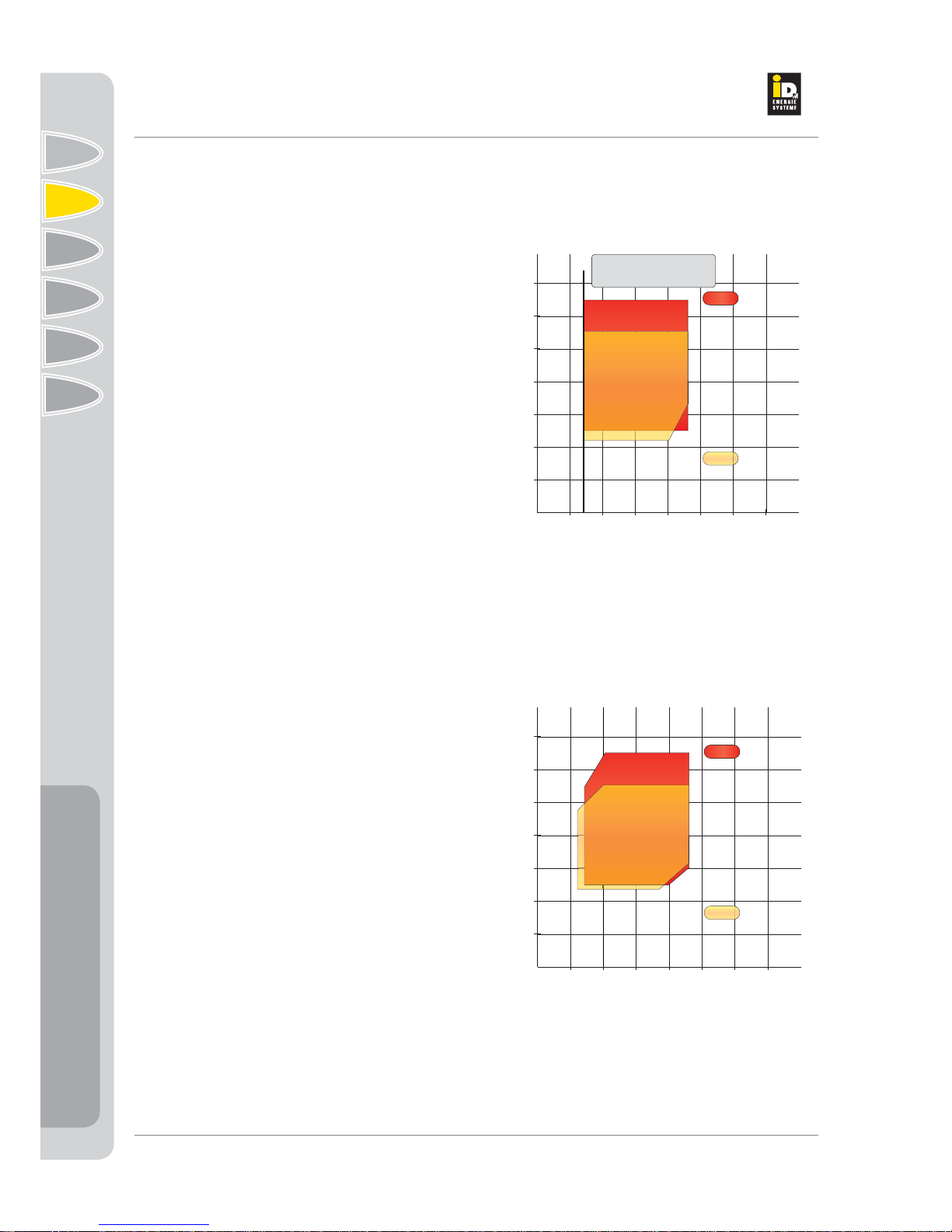
05101520253035
10
Groundwater inlet temperature
Flow temperature
20
30
40
50
60
70
[°C]
[°C]
R134a
R407c
Minimum groundwater
inlet temperature 7°C
-20 -10 010 20 30 40 50
10
Brine inlet temperature
Flow temperature
20
30
40
50
60
70
[°C]
[°C]
R134a
R407c
Description
Description
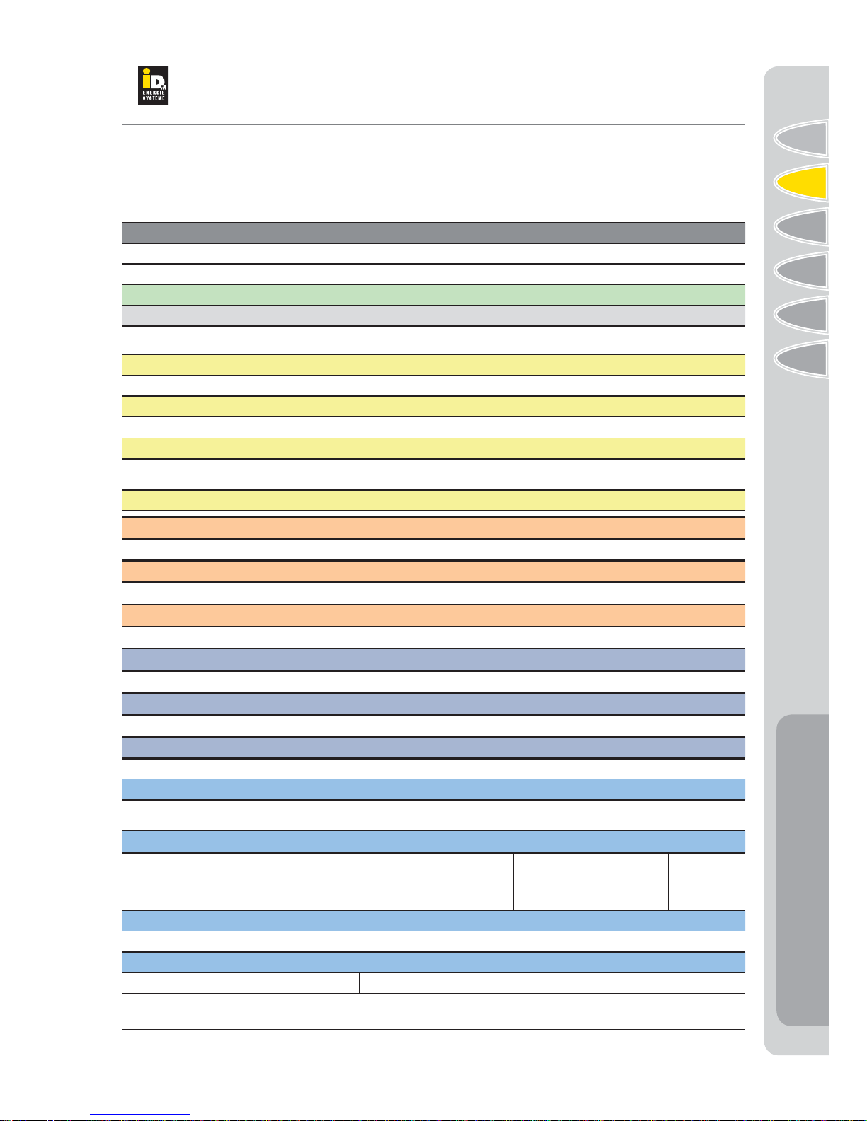
2.7. Operating Limits
TERRA-S/W heat pumps may only be used with heat
conducting media, brine or ground water. Other heat
conducting media are not allowed.
Furthermore, the heating of other liquids as heating
water is not permitted (heating water quality see
Page 25).
By definition, heat pumps are subject to pressure
or temperature-dependent operating limits (see dia-
gram).
The operation of the TERRAheat pump outside these
operating limits is not allowed.
Note:
- The following safety mechanisms are provided for
the safety of the heat pump against potential mal-
functions:
- Combined high and low pressure switch with auto-
matic locking or unlocking by switching the system
off and on (after 3 errors within 24 hours).
- Flow maximum temperature limit with automatic
reset via the Navigator Control.
- Start-up current limiter with rotating field monitoring,
motor current monitoring and phase monitoring for
the compressor.
- Internal winding protection in the compressor
Application range for ground water heat pumps
Application range for brine heat pumps
This manual suits for next models
25
Table of contents
Other IDM-Energiesysteme Heat Pump manuals


Popular Heat Pump manuals by other brands

York
York HMH7 Series Technical guide

Estia
Estia HWS-2101CSHM3-E installation manual

Glen Dimplex
Glen Dimplex LIK 8TES Installation and operating instruction

Automatic Heating
Automatic Heating AHGR32AW17 Installation and instruction manual

Bryant
Bryant EVOLUTION V 288BNV owner's manual

Nibe
Nibe S1256PC Installer manual

Maritime Geothermal
Maritime Geothermal ATW-55 Installation and service manual

AIT
AIT L Split Series operating manual

Friedrich
Friedrich Twintemp YQ07 operating guide

SILENSYS
SILENSYS SILFH4524Z Technical data

Heat Controller
Heat Controller RAH-183G owner's manual

Daikin
Daikin ETSHB16P50EF installation manual


