(C) IDM Energiesysteme GmbH
.
e
eral descriptio
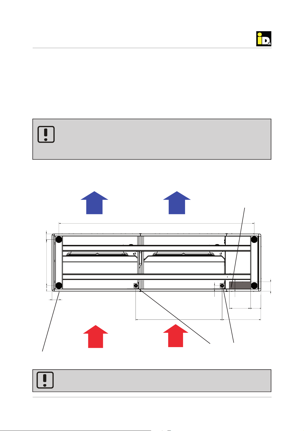
Installation instructions TERRA AL 60 Max
14
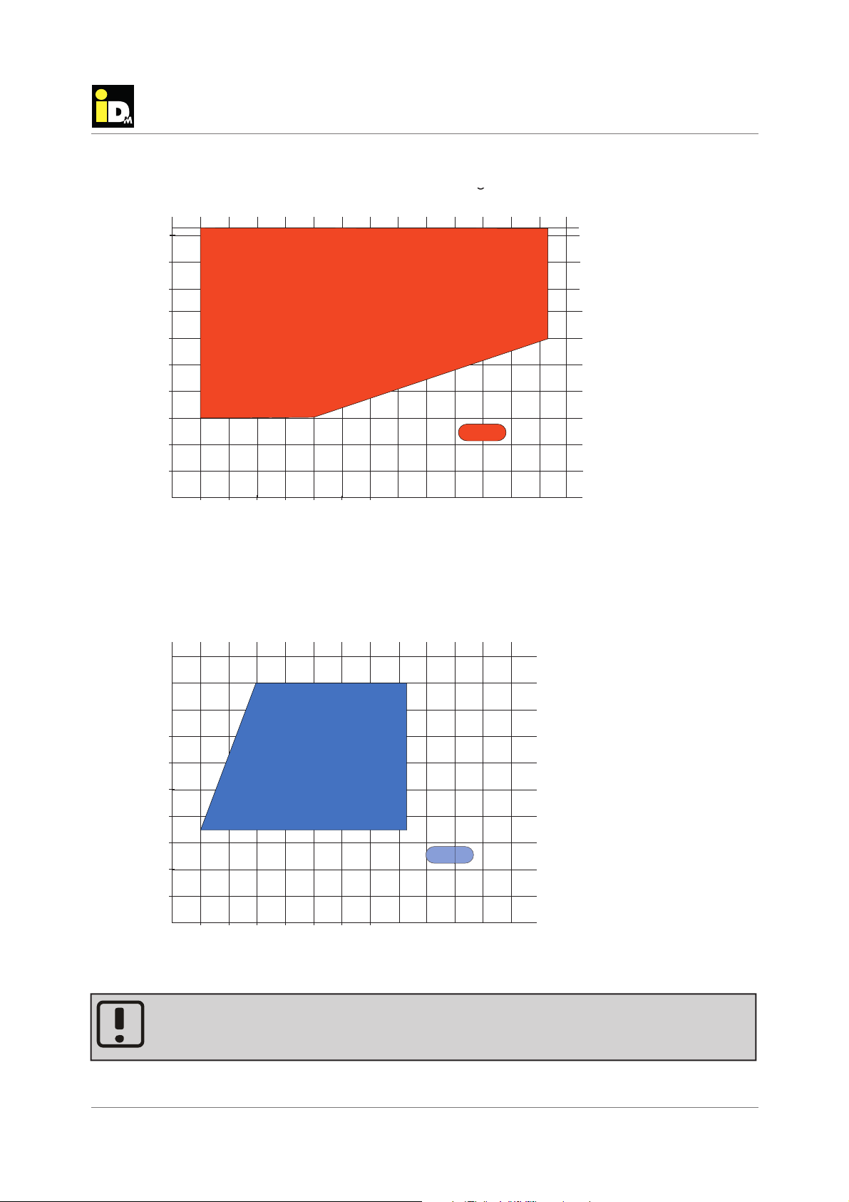
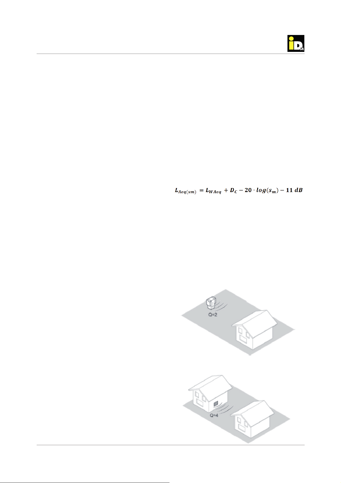
2: Spherical spreading into 1/4 space
(installation next to facade)
1: Spherical spreading into 1/2 space
(free standing installation)
Placement and Installation
4.6. Acoustic evaluation
Sound-power-level
The sound power is the sound energy per second
emitted of a noise source. The sound power level is
specific to the source of sound, independent of dis-
tance and direction and enables an easy comparison
of different sound emitting devices. The sound power
can only be determined via mathematical calculation
according to international standards of the series
ISO 3740 - based on sound pressure level measure-
ments - as well as ISO 9614, which is based on the
measurement of sound intensity. The sound power
level of the heat pumps can be found in the technical
specifications.
Sound-pressure-level
In contrast to the sound power level, the sound pres-
sure level, which is caused by a noise source can be
measured. The measured sound pressure is depen-
dent on the distance from the noise source and the
receiver location (geometrical divergence) as well as
the local conditions. As the sound pressure level is a
measure of the loudness of noise sensed by humans,
the legislation defines limit values, that must not be
exceeded.
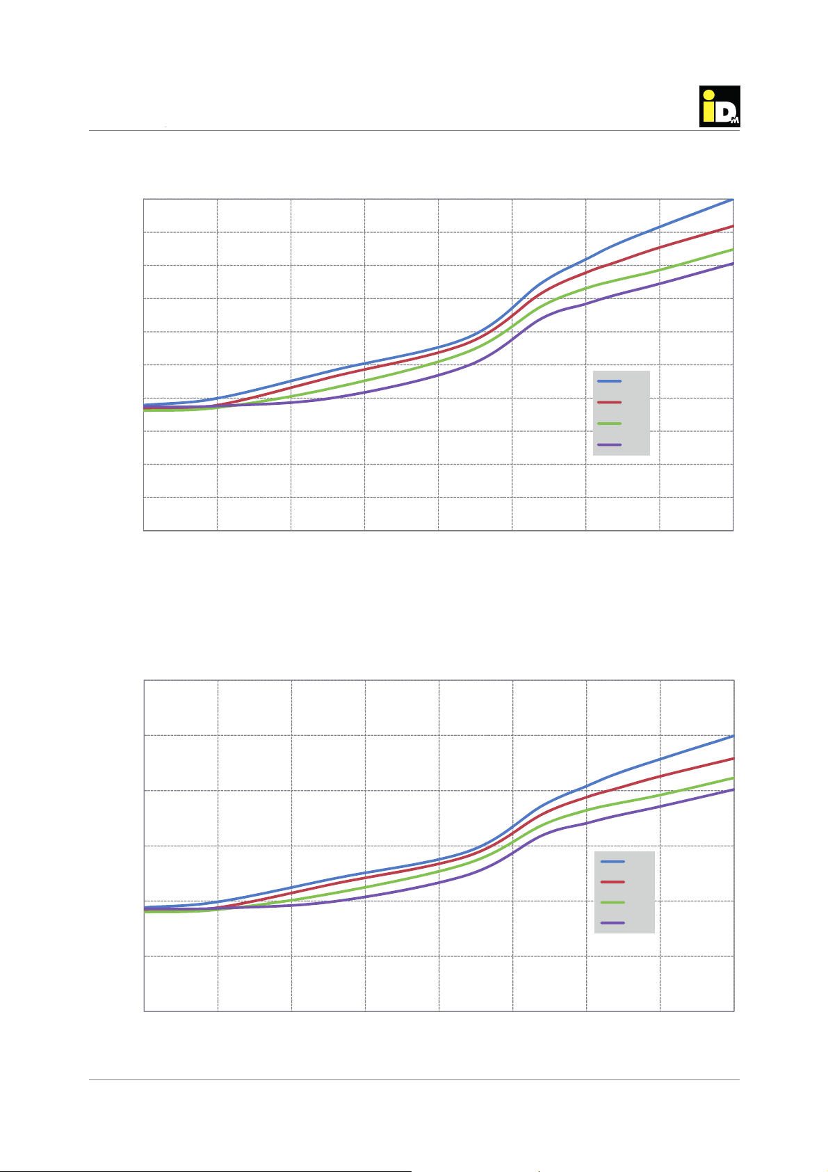
Sound-propagation-outdoor
With increasing distance from a point noise source,
the sound power is distributed on an increasing area
due to spherical spreading. Therefore, the sound
pressure level is continuously decreasing with in-
creasing distance from the noise source to receiver
location. Doubling the distance leads to a reduction of
the sound pressure level of 6 dB(A). Besides the di-
stance from the installation site of the heat pump the
sound, the installation situation and local conditions
also have significant impact on the resulting sound
pressure level at the relevant place of immission.
Major factors of influence are:
• sound attenuation by massive barriers e.g. buil-
dings, walls or different terrain.
• reflection on acoustically hard ground e.g. glass
facade and stone surfaces
• attenuation due to sound absorbing porous sur-
faces e.g. grass, trees
• reinforcement/reduction of by wind speed/direction
Noise-Immission
The noise caused by an source at a certain place is
expressed as Immission, the corresponding sound
pressure level is called Immission level.The immissi-
on level at the relevant place of immission can either
be determined by measurements or calculation e.g.
forecasting method according „TA Lärm“ (German
Noise Prevention Code) especially, which is espe-
cially useful at the stage of planning. According to this
method of calculation, the expected sound pressure
level is calculated on the basis of the sound power
level of the heat pump, the distance of the heat pump
to the receiver location and the installation situation
(directivity correction Dc) of the relevant place of
immission according the following formula:
LWAeq = mean A-weighted sound pressure level [dB]
DC= directionality correction [-]
Sm= distance from noise source to receiver
location [m]
The following figures show the different installation
situations of heat pumps and the corresponding di-
rectivity correction.