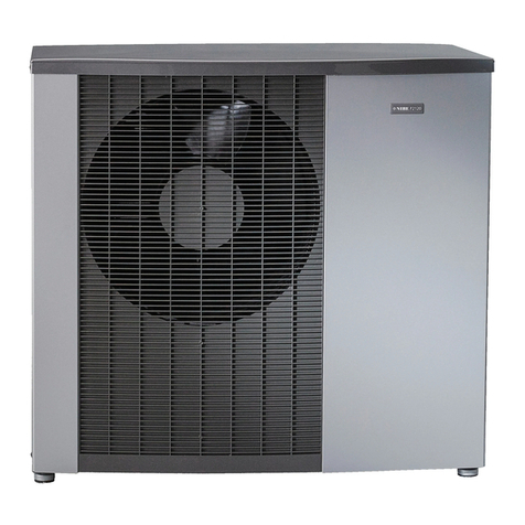
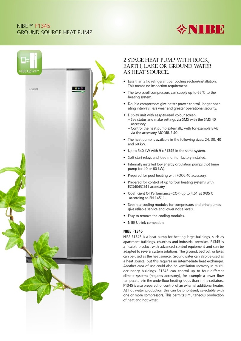
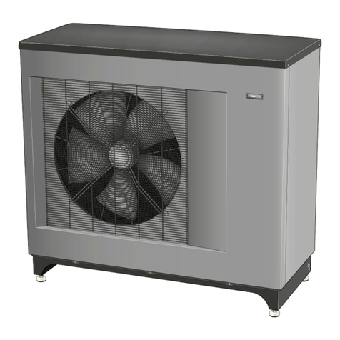
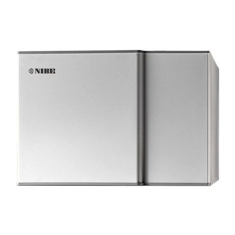
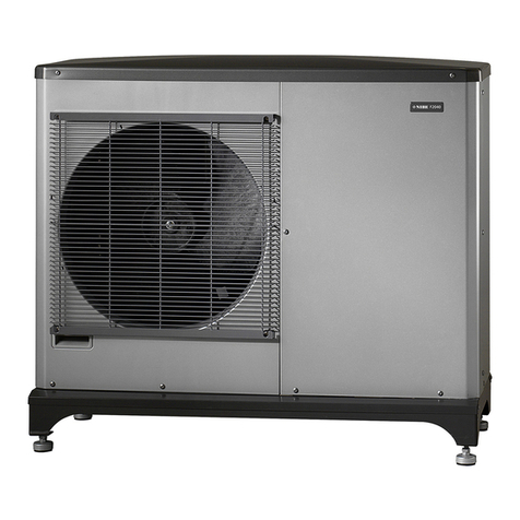
Nibe SPLIT AMS 10 User manual

TEM EN 1821-2
431568
TECHNICAL MANUAL
Air/water heat pump
NIBE AMS10
LEK
LEK
LEK
LEK
UN


41 Important information
4System solution
4Safety information
52 The heat pump design
5Component locations AMS 10-6 (EZ101)
6Component locations AMS 10-8 (EZ101)
7Component locations AMS 10-12 (EZ101)
8Component locations AMS 10-16 (EZ101)
9List of components AMS 10 (EZ101)
10Electrical panel
12Sensor placement
153 System description
15General
164 Description of functions
16Compressor operation
18Fan speed
19Expansion valves (EEV)
20Defrosting
25Oil return
26Compressor protection
28Inverter
28Temperature and low pressure sensor
29Drain pan heater
30Pump down function
335 Component description
33Compressor (GQ10)
344-way valve
37Circuit board
42Expansion valve
42Low pressure transmitter
436 Troubleshooting
43Alarm list
46Troubleshooting guide
60DIP switches, AMS 10
627 Component replacement
62AMS 10
798 Technical data
79Dimensions
83Sound pressure levels
84Technical specifications
88Working area
89Item register
3Table of ContentsNIBE AMS10
Table of Contents

System solution
AMS 10 is intended for installation with NIBE SPLIT
Box HBS 05 and indoor module VVM or control
module SMO. Or with ACVM 270(Does not apply to
AMS 10-6) for a complete system solution.
Safety information
This manual describes installation and service proced-
ures for implementation by specialists.
SYMBOLS
NOTE
This symbol indicates danger to person or ma-
chine .
TIP
This symbol indicates tips on how to facilitate
using the product.
MARKING
The CE mark is obligatory for most products sold in
the EU, regardless of where they are made.
CE
Classification of enclosure of electro-technical equip-
ment.
IP24
Read the Installer Manual.
ENVIRONMENTAL INFORMATION
The equipment contains R410A, a fluorinated green-
house gas with a GWP value (Global Warming Potential)
of 2088. Do not release R410A into the atmosphere.
SERIAL NUMBER
You can find the serial number and the service code
(PF3) on the right-hand side of AMS 10.
PF3
LEK
PF3
LEK
PF3
NIBE AMS10Chapter 1 | Important information4
1 Important information

Component locations AMS 10-6 (EZ101)
UN
FM01
CM
XL53
EEV
XL52
20S
TB
PWB1
DH
QM36
QM37
EB11
GQ1
X1
QN1
GQ10
XL20
QN2
EP1
5Chapter 2 | The heat pump designNIBE AMS10
2 The heat pump design

Component locations AMS 10-8 (EZ101)
LEK
EEV-H
FM01
XL53
EEV-C
LPT
XL52
PWB3
20S
PWB2
TB
PWB1
63H1
QM36
QM37
GQ1
DHEB11
X1
QN3
GQ10
QN1
CM
EB10 XL20
XL20
QN2
EP1
BP8
BP2
NIBE AMS10Chapter 2 | The heat pump design6

Component locations AMS 10-12 (EZ101)
LEK
EEV-H
FM01
CM
XL53
EEV-C
LPT
XL52
TB
63H1
20S
PWB1
PWB2
PWB3
DH
QM37
QM36
GQ1
EB11
X1
QN3
GQ10
QN1
EB10
XL20
QN2
EP1
BP2
BP8
7Chapter 2 | The heat pump designNIBE AMS10

Component locations AMS 10-16 (EZ101)
LEK
DH FM02 CM
PF3
EEV-H
LPT
XL52
XL53
EEV-C
20S
63H1
TB
PWB2
PWB1
PWB3
FM01
QM37
QM36
GQ1
GQ2EB11
X1
QN3
GQ10
QN1
XL20
EB10
EP1
BP2
BP8
NIBE AMS10Chapter 2 | The heat pump design8

List of components
AMS 10 (EZ101)
PIPE CONNECTIONS
Service valve, liquid sideQM36
Service valve, gas sideQM37
Connection, serviceXL20
Connection, gas lineXL52
Connection, liquid lineXL53
SENSORS ETC.
High pressure pressostatBP2 (63H1)
Low pressure transmitterBP8 (LPT)
ELECTRICAL COMPONENTS
Drain pan heaterEB11 (DH)
FanGQ1 (FM01)
FanGQ2 (FM02)
Control boardPWB1
Inverter boardPWB2
Filter boardPWB3
Terminal block, incoming supply and commu-
nication
X1 (TB)
COOLING COMPONENTS
Compressor heaterEB10 (CH)
EvaporatorEP1
CompressorGQ10 (CM)
Expansion valve, heatingQN1 (EEV-H)
4-way valveQN2(20S)
Expansion valve, coolingQN3 (EEV-C)
MISCELLANEOUS
Serial number platePF3
Designations in component locations according to standard IEC 81346-2.
9Chapter 2 | The heat pump designNIBE AMS10

Electrical panel
COMPONENT LOCATIONAMS 10
AMS 10-6
TB
PWB1
UN
TB
Cable holder
AMS 10-8
LEK
PWB3
PWB2
TB
PWB1
LEK
TB
Cable holder
NIBE AMS10Chapter 2 | The heat pump design10

AMS 10-12 / AMS 10-16
Främre el
Bakre el
DH
PWB3
CH
FM01TBF
PWB1
Främre el
Bakre el
PWB2
Diode module
AF module
Reactor
Capacitor
Electrical components AMS 10
Compressor heaterCH
Drain pan heaterDH
FuseF
Fan motorFM01
Control boardPWB1
Inverter boardPWB2
Filter boardPWB3
Terminal block, incoming supply and communica-
tion
TB
Designations in component locations according to standard IEC 81346-2.
11Chapter 2 | The heat pump designNIBE AMS10

Sensor placement
POSITIONING THE TEMPERATURE SENSOR
BE1
QN2
GQ1
GQ10
QN1
EEV-H
BT28 Incoming supply
Outdoor moduleAMS 10-6
BP2
BP1
BE1
QN2
GQ1
GQ10
Incoming supply
QN1 QN3
EEV-H EEV-C
Outdoor moduleAMS 10-8/AMS 10-12
BT28
Tho-A
NIBE AMS10Chapter 2 | The heat pump design12

Outdoor moduleAMS 10-16
BP2
BP1
BE1
QN2
GQ1
GQ2
GQ10
Incoming supply
EEV-C
QN1 QN3
BT28
EEV-H
Current sensorBE1 (CT)
Outdoor temperatureBT28 (Tho-A)
High pressure pressostatBP1 (63H1)
Low pressure transmitterBP2 (LPT)
FanGQ1 (FM01)
FanGQ2 (FM02)
CompressorGQ10 (CM)
Expansion valve, heatingQN1 (EEV-H)
4-way valveQN2 (20S)
Expansion valve, coolingQN3 (EEV-C)
Hot gas sensorTho-D
Evaporator sensor, outTho-R1
Evaporator sensor, inTho-R2
Suction gas sensorTho-S
13Chapter 2 | The heat pump designNIBE AMS10

DATA FOR SENSOR IN AMS 10-6
Tho-D
00 20 40 60 80
20
40
120
160
Resitans
(k )
Temperatur
(°C)
150
90 110 130
60
80
100
140
Resistance
(kΩ)
Temperature
(°C)
Tho-A, R
00 20 40 60 80
4
6
14
18
Resitans
(kΩ)
Temperatur
(°C)
100
8
10
12
16
2
Resistance
(kΩ)
Temperature
(°C)
DATA FOR SENSOR IN AMS 10-8, -12, -16
Tho-D
00 20 40 60 80
30
60
90
120
150
180
210
Resitans
(kΩ)
Temperatur
(°C)
100 120 140 160
Resistance
(kΩ)
Temperature
(°C)
Tho-S, Tho-R1, Tho-R2
00 20 40 60 80
5
10
15
20
Resitans
(kΩ)
Temperatur
(°C)
100
Resistance
(kΩ)
Temperature
(°C)
Tho-A (BT28)
00 10 20 30 40
5
10
15
20
25
30
35
Resitans
(kΩ)
Temperatur
(°C)
50
Resistance
(kΩ)
Temperature
(°C)
NIBE AMS10Chapter 2 | The heat pump design14

General
INSTALLATION REQUIREMENTS
AMS 10-16AMS 10-12AMS 10-8AMS 10-6
0.25 MPa (2.5 Bar)Max pressure, climate system
55/45 °CHighest recommended supply/return temperature at dimen-
sioned outdoor temperature
+65 °CMax temperature in AMS 10
+58 °CMax flow line temperature with compressor
+7 °CMin supply temperature cooling
+25 °CMax supply temp. cooling
30 mMax. pipe length, refrigerant pipe *
80 l80 l50 l20 lMin. volume, climate system during heating, cooling**
100 l100 l80 l50 lMin. volume, climate system during underfloor cooling**
0.57 l/s0.57 l/s0.38 l/s0.29 l/sMax flow, climate system
0.29 l/s0.29 l/s0.19 l/s0.19 l/sMin flow, climate system, 100 % circulation pump speed (de-
frosting flow)
0.15 l/s0.15 l/s0.12 l/s0.09 l/sMin flow, heating system
0.20 l/s0.20 l/s0.16 l/s0.11 l/sMin flow, cooling system
*AMS 10-6: If the length of the refrigerant pipes exceeds 15 metres, extra refrigerant must be added at a rate of 0.02 kg/m.
AMS 10-8/12/16: If the length of the refrigerant pipes exceeds 15 metres, extra refrigerant must be added at a rate of 0.06 kg/m.
** Refers to circulating volume.
External circulation pump must be used when the pressure drop in the system is greater than the available external pressure. In such cases,
a bypass line with a non-return valve must also be installed.
A bypass valve must be used if min. system flow cannot be guaranteed.
15Chapter 3 | System descriptionNIBE AMS10
3 System description

Compressor operation
MAX SPEED
Max. speed can be restricted in menu 9.1.9. Only pos-
sible with ACVM270.
AMS 10-6 (rps)Temperature at BT28
11013 °C or lower
90Between 13°C to 17 °C
7517 °C or higher
AMS 10-16
(rps)
AMS 10-12
(rps)
AMS 10-8
(rps)
Temperature
at BT28
120120118-2 °C or lower
858581Between -2°C
to 18 °C
85607418 °C or high-
er
Max speed at high outdoor temperature:
AMS 10-6 (rps)Temperature at BT28
10622 °C or higher
75Between 9°C to 22 °C
609 °C or lower
AMS 10-16
(rps)
AMS 10-12
(rps)
AMS 10-8
(rps)
Temperature
at BT28
77808640 °C
757567Between
40°C to 46 °C
70756046 °C or high-
er
MIN SPEED
Speed AMS
10-12/-16
(rps)
Speed AMS
10-8 (rps)
Speed AMS
10-6 (rps)
State
202012Cooling mode
252012Heating mode
Min speed during high condensing in heating mode:
Lowest compressor speed during heating operation
changes according to following table:
Speed AMS 10-6 (rps)
40/30*
11°C 13°C
16°C 17°C
30 rps
40 rps
* Condenser temperature or liquid line temperature,
whichever is highest
Speed AMS 10-12/-16 (rps)Speed AMS 10-8 (rps)
35*40*
52 °C 54 °C
35 rps
50°C 52 °C
40 rps
* Condenser temperature or liquid line temperature,
whichever is highest
Min speed at low outdoor temperature:
Speed AMS 10-6
(rps)
State
35ACooling mode
45B
30AHeating mode
40B
AMS10-6
Cooling mode
Outdoor temperature
Normal
9 11 22 25 (°C)
A rps
B rps
NIBE AMS10Chapter 4 | Description of functions16
4 Description of functions

Normal
1
1 13 16 17 (°C)
A rps
B rps
Heating mode
Outdoor temperature
Speed AMS
10-12/-16
(rps)
Speed AMS
10-8 (rps)
State
00A1Cooling mode
+15+15A2
00A3Heating mode
+100A4
+20+10A5
+30+20A6
Cooling mode Heating mode
A2
A1
510
Outdoor temperature
A6
-20 -18
-10 -8
02
A5
A4
A3
Outdoor temperature
THE COMPRESSOR'S SPEED CHANGE
The compressor’s greatest change in speed is
6 rps/30 sec. Above 100 rps, the change in speed is
2 rps/30 sec. (applies to AMS 10-8).
COMPRESSOR START
The compressor restarts if the following conditions are
met:
• The inner unit sends start signals.
• More than three minutes have passed since the
compressor was stopped.
The compressor’s speed is calculated by AMS 10 which
requests the necessary output.
At first start-up in heating operating mode, after the
current has been switched on, the outdoor unit will delay
the compressor start by 30 minutes in order to prevent
oil being drained from the compressor.
During the waiting period, the text "protection" or "pro-
tection mode" may be presented in the indoor module’s
display (does not apply to AMS 10-6).
START PROCEDURE FOR THE COMPRESSOR
Process 1
The compressor usually starts with process 1.
The compressor starts with the speed in “A rps”.
Certain conditions change the start speed to “C rps”:
• In cooling operation, when the outdoor temperature
(Tho-A) is greater than 35 °C.
• In heating operation, when HM in (BT3) is 48 °C or
higher*.
Between
7 and 9
minutes
Between
3 and 7
minutes
Between
0 and 3
minutes
Time from
start
State
C rpsB rpsA rps
120120120Speed
AMS 10-6
Cooling
mode
120120120Speed
AMS 10-6
above
0° C
Heating
mode
755648Speed
AMS 10-6
below
0° C
C rpsB minA rpsState
-420Speed
AMS 10-8
Cooling
mode
30455Speed
AMS 10-
12/-16
-440Speed
AMS 10-8
Heating
mode
30255Speed
AMS 10-
12/-16
* For AMS 10-8, compressor revving stops when the
pressure difference is greater than 0.34 MPa. In cooling
operation, it stops when the low pressure is 0.8 MPa.
17Chapter 4 | Description of functionsNIBE AMS10

Process 2
First start after the heat pump has been powerless.
Cooling operation:
The compressor starts with the speed in ”A rps”.
At outdoor temperatures above 35 °C, the start value
speed changes to “C rps”.
Heating operation:
The compressor starts with the speed in “A rps”.
At HM in (BT3) temperature above 48 °C, the start speed
is changed to “C rps”
5 minutes
and higher
Between
1 and 5
minutes
Between
0 and 1
minute
Time from
start
State
C rpsB rpsA rps
-3240Speed
AMS 10-6
Heating
mode
C rpsB minA rpsState
_1020Speed
AMS 10-8
Cooling
mode
301055Speed
AMS 10-
12/-16
___Speed
AMS 10-8
Heating
mode
30 *255Speed
TAMS 10-
12/-16
*The compressor speed is locked at A rps for B minutes
after start-up.
Process 3
Compressor starts in heating operation after having been
switched off for 2 hours or more.
The compressor starts with the speed in “A rps”.
At HM in (BT3) temperature above 48 °C, the start speed
is changed to “C rps”
B minA rpsState
340Speed AMS
10-6
Heating
mode
1540Speed AMS
10-8
1555Speed AMS
10-12/-16
*The compressor speed is locked at A rps for B minutes
after start-up.
Fan speed
The fan starts at the lowest speed. This does not apply
to AMS 10-6, which is regulated according to the com-
pressor’s speed.
The relationship between the evaporator’s temperature
and outdoor temperature limits the fan speed as follows.
COOLING MODE
Fan speed (rpm)AMS 10-6
MaxMin
850150
Min
fan
speed
(rpm)
Max fan speed (rpm)AMS 10-8
DCBATho-A
Tho-R
130710850850850a
190600710850850b
190400600710710c
190200400600600d
Tho-R
d
25 30
33 40
43 53
c
b
a
Tho-A
D
15 18
30 37
46 48
C
B
A
Fan speed (rpm)AMS 10-12/-16
MaxMin
870190
Cooling operation:
The fan speed is checked every 15 seconds so that the
heat exchanger temperature (Tho-R1, -R2), the highest
one, is within a certain range.
Fan speedSensor temperature Tho-R
Reduction by 10 rpmBelow 30 °C
NIBE AMS10Chapter 4 | Description of functions18

Fan speedSensor temperature Tho-R
Maintains the speedBetween 30 °C and 45 °C
Increase by 10 rpmAbove 45 °C
HEATING MODE
Fan speed (rpm)AMS 10-6
MaxMin
850150
Min fan
speed
(rpm)
Max fan speed (rpm)AMS 10-8
CBATho-A
Tho-R
390710600600a
390850710600b
390850850710c
Tho-R
c
-2 0
13
b
a
Tho-A
C
39
12 15
B
A
Fan speed (rpm)AMS 10-12/-16
MaxMin
740390
The fan speed is checked every 15 seconds so that the
temperature difference between the outdoor temperat-
ure (Tho-A) and heat exchanger temperature (Tho-R1, -
R2), whichever is the highest, is within a certain range.
Fan speed(Tho-A) - (Tho-R)
Reduction by 10 rpmLess than 3 °C
Maintains the speedBetween 3 °C and 6 °C
Increase by 10 rpmAbove 6 °C
When the outdoor temperature (Tho-A) is greater than
25 °C, the fan speed is checked by the low pressure
(LPT).
Fan speedLPT
Reduction by 10 rpmHigher than 1.1 MPa
Maintains the speedBetween 1.0 and 1.1 MPa
Increase by 10 rpmBelow 1.0 MPa
Expansion valves
(EEV)
Every time the machine is powered up, the expansion
valve will seek its original position. This is clearly heard
with a knocking sound. The expansion valve has 480
pulses from limit position to limit position.
COOLING MODE
EEV-C regulates so that overheating is 5 K.
EEV-H is fully open when the compressor is in operation.
HEATING MODE
EEV-H regulates so that overheating is between 3 and
5 K.
EEV-C regulates so that subcooling is as per the diagram.
Zone A
Zone B
Ambient temp Tho-A(°C)
15 18
518
Temperature dierence between water inlet/outlet
Zone B
Zone A
Target SubCool
T sc (°C)
14
5
Zone B
Zone A
Set point value subcooling
Temperature difference between
incoming and outgoing liquid.
Zone B
Zone A
Outdoor temperature Tho-A (°C)
19Chapter 4 | Description of functionsNIBE AMS10

Defrosting
START CONDITIONS FOR DEFROSTING
If the following conditions A or B are met, defrosting
starts (Does not apply to AMS 10-6).
Defrosting conditions A:
• a) When the accumulated operating time for the
compressor exceeds 37 minutes after the previous
defrosting, and more than 30 minutes after the previ-
ous start of heating operation.
• b) At least 5 minutes have passed after compressor
start.
• c) When one of the following conditions is met:
–c1) When the association between the outdoor unit’s
heat exchanger temperature (Tho-R1 or -R2,
whichever is the lowest) and the outdoor temperat-
ure (Tho-A) is in the temperature range for defrosting
start.
– c2) When the association between the suction gas
evaporation temperature (SST) and Tho-A is within
the temperature range.
Defrosting will not start under the following condi-
tions:
- Less than 10 minutes have passed since the
compressor started.
- The outdoor temperature is higher than 4°C.
Condition c1
-20 -18 0 6
-27
-20
-6
L gsta temperaturen av Tho-R1 och Tho-R2
(°C)
Uteluftstemperatur Tho-A
(°C)
DIP-switch SW3-1 OFF
DIP-switch SW3-1 ON
Temperature Tho-R1/R2
(°C)
Outdoor air temperature Tho-
A
(°C)
DIP switch SW3-1 ON
DIP switch SW3-1 OFF
Defrosting range
Condition c2
-18 -15 0 6
-31
-24
-10
Förångningstemperaturen SST
(°C)
Uteluftstemperatur Tho-A
(°C)
DIP-switch SW3-1 OFF
DIP-switch SW3-1 ON
Evaporation temperature SST
(°C)
Outdoor air temperature Tho-
A
(°C)
Defrosting range
DIP switch SW3-1 ON
DIP switch SW3-1 OFF
Defrosting conditions B:
• a) Defrosting can be started when the accumulated
operating time for the compressor has reached 30
minutes, if the previous defrosting was concluded
because of “max. defrosting time”.
• b) At least 5 minutes have passed after compressor
start.
You can find information about DIP switches on page
60.
Defrosting AMS 10-6
Defrosting starts if all the conditions below are satisfied.
Defrosting conditions:
• a) When the accumulated operating time for the
compressor exceeds 35 minutes after the previous
defrosting and 35 minutes after previous start of
heating operation.
• b) The temperature sensor Tho-R (BT28) has been
lower than -5 °C for three minutes.
• c) The temperature sensor Tho-R minus Tho-R is
greater than or equal to 7 °C.
Condition AMS10-6
-20 -15 0 2
-29
-22
-5
Värmeväxlartemperaturen Tho-R
(°C)
Uteluftstemperatur Tho-A
(°C)
Heat exchanger temperature Tho-R
(°C)
Outdoor air temperature Tho-
A
(°C)
Defrosting range
NIBE AMS10Chapter 4 | Description of functions20
Table of contents
Other Nibe Heat Pump manuals
Popular Heat Pump manuals by other brands

Dimplex
Dimplex A8M installation manual

ES Nord
ES Nord BA-H050 instruction manual

Nordyne
Nordyne iQDrive Split System Heat Pump installation instructions

Fondital
Fondital WHDHP 300 SSH Installation, use and maintenance handbook

York
York BQ 036 Technical guide

Dimplex
Dimplex SI 35TUR Installation and operating instruction

Lennox
Lennox LRP14G installation instructions

Ideal Boilers
Ideal Boilers 4.5 Installation

Fujitsu
Fujitsu FO14R Series installation instructions

Trane
Trane Horizon OABE/F Series Installation, operation and maintenance

Sinclair
Sinclair STHERM GSH-60IRB Service and installation manual

ALLIANCE
ALLIANCE ALLPH35R410 Installation & operation manual