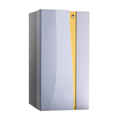
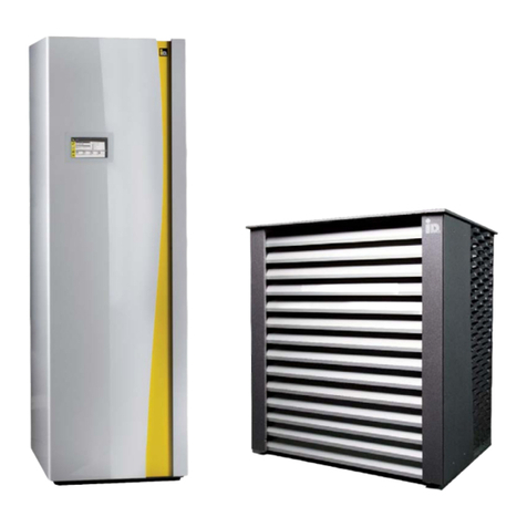
iDM AERO ILM 2-7 User manual

Modulation air-water-heat pumps
for Indoor Installation
DIE E
N
ER
G
IEFA
M
ILI
E
TECHNICAL DOCUMENTATION
INSTALLATION INSTRUCTIONS
HEAT PUMPS FROM AUSTRIA
www.idm-energie.at
812583 Rev.4 - Translation of original instructions
AERO ILM 2-7
AERO ILM 4-13
Additional Model:
HGL
with NAVIGATOR 2.0 Control

(C) IDM ENERGIESYSTEME GMBH
2
.
G
e
n
eral descriptio
n
Installation instructions AERO ILM
2
Contents
Contents
1. GENERAL DESCRIPTION 4
1.1. General information 4
1.2. Safety instructions 4
1.3. Transport and storage 4
1.4. Sound emission 4
1.5. Construction drying and floating screed heating 4
1.6. Minimum heating temperture for air heat pumps 4
1.7. Service and maintenance 5
1.8. Cleaning 5
1.9. Ice-covering weather-shield grilles 5
1.10. Installation area 5
1.11. Information on environmental protection 6
1.12. Piping and pipe-wall-ducts 6
1.13. Installation of additional components 6
1.14. Standards and guidelines 6
1.15. Description 6
1.16. Intended use 6
1.17. Scope of delivery 7
1.18. Accessories 7
2. TECHNICAL DATA 8
2.1. Dimensions of AERO ILM 2-7 and AERO ILM 4-13 8
2.2. Technical data 9
3. DIMENSIONING 11
3.1. Heating performance diagrams AERO ILM 2-7, according EN14511 12
3.2. Heating performance diagrams AERO ILM 4-13, according EN14511 14
3.3. Limitations of use 16
4. CONNECTIONS AND CABLE DUCTS 18
4.1. Cable and piping ducts 19
4.2. Hydraulic connections to the heat pump 19
5. INSTALLATION 20
5.1. Installation instructions 20
5.2. Heating connections 20
5.3. Condensation run-off 20
5.4. Air duct 21
5.5. Acoustic evaluation 21
5.6. Decoupling of buildings 24
5.7. Installation location 25
5.8. Space requirements and accessibility 25
5.9. Corner installation 26
5.10. Installation with a straight air duct 30
5.11. Installation with 90 ° air duct 33
5.12. Installation of flexible air hose - air outlet sideways 36
5.13. Installation of flexible air hose - air outlet to the top 40
5.14. Modification from the right-hand to left-hand outlet side 44
5.15. Opening front panel 44

(C) IDM ENERGIESYSTEME GMBH Installation instruction AERO ILM 3
Contents
Contents
Important information on assembly and
operation of the heat pump. These in-
structions must be observed!
Space for the customer service
phone No.
5.16. Transport provisions 45
6. HEATING CONNECTIONS 46
6.1. Requirements heating connections 46
6.2. Safety device 46
6.3. AERO ILM with unregulatet direct heating circuit and Hygienik without separating plate 47
6.4. AERO ILM with unregulated direct heating circuit and AQA 48
6.5. AERO ILM with Hygienic with separating plate and mixer circuits 49
6.6. AERO ILM with cooling buffer and hygienic with layer separate plate 50
6.7. AERO ILM HGL with TERMO 100 and Hygienik without separating plate and cooling circuit 51
6.8. AERO ILM HGL with Hygienic with separating plate and mixer circuits 52
6.9. AERO ILM HGL with Hygenik with separating plate and cockle stove 53
6.10. AERO ILM HGL with cooling and HGL usage in one step 54
6.11. Additional hydraulic connection for heat recovery 55
7. ELECTRICAL CONNECTION 56
7.1. Power supply 56
7.2. Feedthrough for wiring 57
7.3. Configuration of outputs and inputs 57
7.4. Connection diagram for the electric components 58
7.5. Configuration of sensors 59
7.5.1. Sensor configuration 59
7.5.2. Flow temperature sensor 59
7.6. Connecting the outputs 59
7.7. Grounding the system 59
7.8. Maximum delimitation in underfloor heating 59
7.9. Connecting external specifications 0-10 V 60
7.10. Sum signal zone valves 60
7.11. EMC compatibility 60
8. START-UP 61
8.1. Information regarding the start-up 61
8.1.1. Switching the heat pump on for the very first time. 61
8.1.2. Operation 61
8.2. Errors 61
9. APPENDIX 62
9.1. AERO ILM 2-7 - Performance data heating - detailed 62
9.2. AERO ILM 2-7 - Performance data cooling - detailed 63
9.3. AERO ILM 4-13 - Performance data heating - detailed 64
9.4. AERO ILM 4-13 - Performance data cooling - detailed 65
9.5. AERO ILM - Product data sheet 66
9.6. Declaration of conformity 67
Subject to changes with regard to engineering and design!

(C) IDM ENERGIESYSTEME GMBH
1
.
G
e
n
eral descriptio
n
Installation instructions AERO ILM
4
1. General description
1.1. General information
By purchasing this system you have decided in favor
of a modern and cost-effective heating system. Con-
tinuous quality controls and improvements as well as
functional checks at our production facilities guaran-
tee technically error-free equipment.
Please read this documentation carefully. It con-
tains important instructions for a correct installa-
tion, for the reliable and an economical operation
of the system.
1.2. Safety instructions
Installation and maintenance operations can be as-
sociated with dangers resulting from high system
pressures, high temperatures and voltaged parts.
Heat pumps may only be installed by competent spe-
cialist and exclusively put into operation by a cus-
tomer service specialist trained for that purpose by
iDM-Energiesysteme GmbH.
If maintenance work is being done on the heat pump,
disconnect the system and ensure that it is volt-free
and provided with a safeguard to prevent unintention-
al restarting. Furthermore all safety instructions in the
respective documentation or on instruction plates af-
fixed to the heat pump itself resp. all other pertinent
safety regulations shall be observed.
1.3. Transport and storage
In transporting the heat pump ensure that it is never
tilted by more than 30°. Do not remove the transport
packaging until the heat pump has reached its instal-
lation location. Heat pump components must not be
stored outside. Heat pumps must not be stored in
humid rooms or dusty environments. The transport
fixtures as described in the following assembly
instructions are used to transport the heat pump
manually. The transport fixtures must not be used for
transporting the components with a crane or similar
hoisting equipment.
1.4. Sound emission
AERO heat pumps run extremely smoothly due to
their construction. It is nevertheless important to
ensure that the heating room is located beyond the
noise-sensitive living area and furnished with a well-
closing door.
1.5. Construction drying and floating screed
heating
During drying or screed heating, the heat require-
ment can exceed the heating capacity many times
over due to the high moisture content of the build-
ing. The heat pump system is not designed for this
increased heat requirement. In continuous operation
of the heat pump, there is a risk that the outdoor unit,
the deep probe or the surface collector will ice-up due
to overload. For this reason, the increased heat re-
quirement must be covered by units to be provided
by the customer.
1.6. Minimum heating temperture for air heat
pumps
In order for air heat pumps to perform defrosting
properly, a minimum temperature of 20 °C on the
heating side is required. During the heating season,
this temperature must not be fallen below. If this
temperature is not reached, a bivalent heat generator
must be used to reheat to the minimum temperature
of 20 °C. The temperature must not be lower than
20 °C during the heating season. The air heat pump
must not be switched offduring this time.

(C) IDM ENERGIESYSTEME GMBH Installation instructions AERO ILM 5
General description
1.7. Service and maintenance
Regular maintenance as well as an inspection and
maintenance of all important system components
guarantees a reliable and low-price operation of the
system in the long term. We recommend you to sign
a maintenance contract with your competent cus-
tomer service.
1.8. Cleaning
If necessary, the AERO heat pump can be cleaned
using a moist cloth. The use of cleaning agents is not
recommended.
The air vent package in the air heat exchanger
has to be inspected regularly and cleared of any im-
purities (e.g. leaves,...), if necessary.
The condensate run offhose can be disconected by
opening the tube clamp on the condensate bin. Now
the bin and the tube can be inspected and cleaned.
- In order to minimize oscillations and sounds
within buildings, heat pumps should be decou-
pled as far as possible from the building mass.
It is principally recommended to avoid installing
heat pumps on ceilings and floors in lightweight
construction. In the case of floating floor screed,
floor screed and impact sound insulation should
be omitted around the heat pump.
- The installation in wet or damp environments or
in areas exposed to dust or explosion hazards is
non-permissible.
- If refrigerant escapes from the installation site,
this must not enter adjacent rooms, stairways,
yards, corridors or drainage systems and a
hazard-free drainage must be ensured.
- In the case of danger, leave the installation site
immediately.If the size of the installation site falls
below the requested minimum size, this has to
be designed as machinery room in compliance
with EN 378.
- If the emergency ventilation is not sufficient,
mechanical ventilation must be provided. A
mechanical ventilation shall be installed with
an independent emergency control beyond the
installation site and near the door to that area.
- Heat pumps must not be installed in rooms with
high EMC load!Air intakes and outlets have to be
safeguarded against theft by appropriate on-site
measures.
- The AERO ILM heat pump has to be
installed in a frost-proof room! (room
temperature must lie between 5 °C and
25 °C!)
To prevent water damage, the conden-
sate bin and the condensate hose have
to be checked regularly for contamination.
1.10. Installation area
1.9. Ice-covering weather-shield grilles
Depending on the weather and outdoor humidity, it
may happen that there will be formed an icy coverng
on the wheather-shield grilles of the heat pump. This
effect is common occuring in nature. This covering
must be removed by the heat pump operator during
this weather periods.

(C) IDM ENERGIESYSTEME GMBH
1
.
G
e
n
eral descriptio
n
Installation instructions AERO ILM
6
General description
The lower the maximum flow temperature
is, the higher the coefficient of perfor-
mance (COP) of the heat pump will be.
1.15. Description
AERO ILM is a compact air-water-heat pump with
modulating scroll capsule compressor with largely
dimensioned multi-row Al/Cu finned tube evaporator.
By a special speed-controlled radial fan large volume
flows can be achieved at low speeds.
A copper-welded stainless steel plate heat exchanger
is used as condenser. The machine frame consists of
a strong metal profile. The cover panels are insulated
perfectly. The housing is thus completely without a
thermal bridge and thus features optimum sound in-
sulation values.
The heat pump is complete from a hydraulic viewpoint
and features a high-efficiency loading pump, the safe-
ty device, an expansion container, the electric heating
rod, the priority valve respectively the HGL-technolo-
gy, a flow switch and all necessary sensors.
The heating controller (Navigator 2.0) developed es-
pecially for this system offers a variety of additional
applications, e.g. Smart Grid, Remote Control or op-
eration via a smart phone.
The heat pump is designed in compact construction,
the evaporator is mounted in the top part of the heat
pump casing. The heat pump is filled with refrigerant
and is tested in the plant to ensure its perfect function.
1.16. Intended use
For monovalent heating and cooling of detached and
semi-detached houses in appropriate climatic envi-
ronments. The building should be furnished with a
low-temperature heating (e.g. underfloor heating, wall
heating, low-temperature radiator heating ...).
The heat pump must be used only for domestic, but
not for commercial operation, eg production of pro-
cess heat.
For the installation of the heat pump all
pertinent national and international lay-
ing, installation, accident prevention and
safety regulations in connection with the
installation of pipeline systems and elec-
tric components and equipment as well as
instructions in this assembly manual must
be observed.
1.11. Information on environmental protection
Heat pumps are electronic devices of
high-quality material which must not be
disposed of in the same way as house-
hold waste. They must be disposed of in
a professional and appropriate manner
pursuant to the regulations of the local
authorities. Disposal contrary to the
regulations may lead damage the envi-
ronment and health with the exception
of sanctions imposed on law breakers.
1.12. Piping and pipe-wall-ducts
All pipelines and wall ducts must be discharged in
compliance with standards, according heat-insula-
tion, sound-decoupling and water-carrying pipes in a
frost-proof manner.
1.13. Installation of additional components
The installation of additional components which have
not been verified with the equipment may impair the
function. No warranty or liability shall be assumed for
any damage resulting therefrom.
1.14. Standards and guidelines
These comprise among others:
- the generally valid accident prevention and safety
regulations
- the provisions regarding environmental protection
- the regulations of the professional associations
- the pertinent laws, standards, regulations and pro-
visions, e.g. DIN, EN, DVGW, VDI and VDE.
- Provisions of the local public utilities.

(C) IDM ENERGIESYSTEME GMBH Installation instructions AERO ILM 7
General description
AERO ILM heat pumps function with the safety re-
frigerant R410A which, if in the event of a proper as-
sembly and installation circulates in a closed circuit,
represents practically no environmental impact.
1.17. Scope of delivery
- Heat pump aggregate with modulating scroll cap-
sule compressor (AERO ILM 4-13) or rolling piston
compressor (AERO ILM 2-7)
- Inverter with patented CIC-technology
- Copper-welded stainless steel plate heat exchanger
as condenser
- HGL-plate heat exchanger (only ILM HGL type)
- Finned tube Al/Cu evaporator package
- Speed-controlled radial fan
- Refrigerant collection and dehydration
- Liquid separator
- 2 pcs. electronic expansion valves
- Refrigerant level indicator
- Pressure sensors for high and low-pressure moni-
toring
- Cartridge pressure control switch for high-pressure
monitoring
- Installed switching valve for cooling/defrosting
- Suction air sensor
- High-efficiency loading pump
- 3-way valve for priority mode (ILM type) orHGL-
valve for HGL-mode (ILM HGL type)
- Flow switch
- Electrical heating rod 6 kW for possible subsequent
heating
- Heat and sound-insulated cover panels
- colored 7” touch display
- 3 pcs. flexible connection hoses
- Condensate drain tube
- nonreturn valve (loose)
- 2 pcs. sound reduction mats to place below the
heat pump
- network connector for myIDM integration
1.18. Accessories
see iDM price list

(C) IDM ENERGIESYSTEME GMBH
2
.
G
e
n
eral descriptio
n
Installation instructions AERO ILM
8
775
1011
770
120
850
960
1851
764
828
912
600
750
1010
120
912
828
780
750
1010
780
780
(without front)
View from the
right (outlet)
Tear view
(inlet)
Front view
Top view
Technical data2. Technical data
2.1. Dimensions of AERO ILM 2-7 and AERO ILM 4-13

(C) IDM ENERGIESYSTEME GMBH Installation instructions AERO ILM 9
Technical data
Heatpump type AERO ILM 2-7 AERO ILM 4-13
Additional model -
without HGL
HGL
without HGL
Energy efficiency class
35 °C 55 °C 35 °C 55 °C
Performance data heating with nominal speed Unit
Heating capacity at A2°C/W35°C kW 3.87 7.11
Heating capacity A7°C/W35°C kW 4.51 8.28
Heating capacity A-7°C/W35°C kW 2.84 5.50
Power consumption at A2°C/W35°C kW 0.89 1.73
Power consumption at A7°C/W35°C kW 0.89 1.74
Power consumption at A-7°C/W35°C kW 0.86 1.68
COP at A2°C/W35°C - 4.32 4.11
COP at A7°C/W35°C - 5.06 4.76
COP at A-7°C/W35°C - 3.28 3.27
Performance data cooling with nominal speed
Cooling cpacity at A35°C/W18°C kW 5.09 9.48
Cooling cpacity at A35°C/W7°C kW 3.44 6.76
Power consumption at A35°C/W18°C kW 1.13 2.31
Power consumption at A35°C/W7°C kW 1.09 2.23
EER at A35°C/W18°C - 4.50 4.10
EER at A35°C/W7°C - 3.16 3.03
Sound data according EN 12102 1
Outside air inlet - nominal/maximum dB(A) 48/55 55/59
Outside air outlet - nominal/maximum dB(A) 48/58 53/57
Noise-reduced operation (air inlet) dB(A) 53 57
Noise-reduced operation (air outlet) dB(A) 51 55
Indoor - nominal/maximum dB(A) 44/49 4253
The sound pressure level can be calculated with the iDM-sound calculation tool
Dimensions HxWxD mm 1850/910/830 1850/910/830
Tilt hight mm 2028 2028
Weight kg 280 295
1
Sound data with weather shield-grilles, without air hose and without air duct. If the fan speed will be raised, the sound power level raises too. Measurement uncertainty ± 1,5 dB(A)
With the HGL Model, the specified heat output is composed of the heating- and the HGL-heating-output.
Detailed data according the energy efficiency are shown in the appendix.
2.2. Technical data
A+A+ A+ A+

(C) IDM ENERGIESYSTEME GMBH
2
.
G
e
n
eral descriptio
n
Installation instructions AERO ILM
10
Technical data
Heatpump type unit AERO ILM 2-7 AERO ILM 4-13
Maximum heatpump flow temperature ⁵°C 62 60
Nominal flow rate heating water (A7°C/W35°C, ΔT=5 K)
m³/h 0.8 1.42
Flow rate heating water (A7°C/W55°C, ΔT=8 K)
m³/h 0.42 0.77
Integrated loading pump Yonos Para 7.0 Stratos Para 25/1-9
Free residual pressure loading pump at nominal flow rate
kPa 49 77
Pressure loss heating side kPa 15 11
Flow- and return connections heating side R 1“ AG 1“ AG
Flow domestic hot water heater or HGL-flow R 1“ AG 1“ AG bzw. 5/4“ AG
Condensate run-off connection R 35 mm 35 mm
Maximum operating pressure heating side bar 3 3
Residual pressure at maximum speed ¹ Pa 150 110
Nominal air flow rate (A7°C/W35°C
and nominal Compressor speed) m³/h 1,250 2,200
diameter flexible air outlet hose (accessory) mm 560 560
Refrigerant R410A R410A
Quantity of refrigerant 2kg 3.2 6.2
GWP 31924
Minimum size of installation room4m³ 7.3 14.1
Quantity of compressor oil (FV50S) lt. 0.35 1.9
Quantity of compressors qty 1 1
1
If the fan speed will be raised, the sound power level raises too
² AERO ILM heat pumps work with the by the Kyoto protocol detected safety refrigerant R410A, with a global warming potential of 2088.
3
According to the 5th IPCC report
4If the installation room falls below the required minimum size, it must be constructed as a machine room in accordance with EN 378.
⁵The 62°C refers to the max heat pump flow temperature. The resulting lower hot water temperature must be checked in relation to compliance with the drinking water
regulations.
Electrical data unit AERO ILM 2-7 AERO ILM 4-13
Electrical power supply compressor V/Hz
1~
230/50
3~
400/50
Electrical power supply heating element
V/Hz
3~
400/50 or
1~
230/50
3~
400/50
Electrical power supply controller
V/Hz
1~
230/50
1~
230/50
Maximum operating (starting) current of compressor A 15.8 19.0
Maximum power consumption electric heating element A 8.7 8.7
Fuse of control supply A B/Z 13 B/Z 13
Fuse of electrical heating element A if
3~
400/50 B/Z 13
if
1~
230/50 B/Z 32
B/Z 13
Fuse of main power supply compressor A C/K 16 C/K 20
Maximum operating current of fan A 0.24 0.5
Maximum power consumption fan W 56 115
Protection class - IP 20 IP 20

(C) IDM ENERGIESYSTEME GMBH Installation instructions AERO ILM 11
0
2
4
6
8
10
12
14
16
-20-15-10-5 0 5 101520
MAX
NOMINAL
MIN
W35 EN14511
W35 EN14511
W35 EN14
{
outside temperature [°C]
heating capacity [kW]
bivalence point of the
particular heatpump type
standard external temperature
domestic hot water required
building- characteristic line
required heating capacity at
standard external temperature
incl. domestic hot water required
Bivalence
part
heating limit
Dimensioning
An air/water-heat pump should be dimensioned in
such a way that the bivalence point lies between -3
and -10 °C. This guarantees that more than 90 % of
the annual heating requirement (Austria, Germany,
Switzerland) will be covered by the heat pump.
In dimensioning the system the maximum heating
output of the house including the water for domestic
use is calculated.
The standard outside temperature is additionally re-
quired. This is determined by the geographical loca-
tion and can be found on the iDM homepage and ob-
tained from various institutions.
Example:
Detached single-family house in Germany
4 person-household
Domestic water requirements: 4 x 0.25 kW = 1 kW
Heating output requirements 11 kW
Standard outside temperature
Germany: - 16 °C
Off-period factor: 1.1
Heating energy required:
(domestic water requirements + heating output requirements) x off-period factor = 13.2 kW
Heating performance diagram AERO ILM 4-13
3. Dimensioning

(C) IDM ENERGIESYSTEME GMBH
3
.
G
e
n
eral descriptio
n
Installation instructions AERO ILM
12
0
2
4
6
8
10
12
-20 -15 -10 -5 0 5 10 15 20
MAX
NOMINAL
MIN
heating capacity [kW]
outside temperature [° C]
0
2
4
6
8
10
12
-20 -15 -10 -5 0 5 10 15 20
MAX
NOMINAL
MIN
heating capacity [kW]
outside tem
p
erature
[
° C
]
Dimensioning
3.1. Heating performance diagrams AERO ILM 2-7, according EN14511
Heat output with flow temperatures of 35 °C
Heat output with flow temperatures of 45 °C

(C) IDM ENERGIESYSTEME GMBH Installation instructions AERO ILM 13
0
2
4
6
8
10
12
-20 -15 -10 -5 0 5 10 15 20
MAX
NOMINAL
MIN
heating capacity [kW]
outside tem
p
erature
[
° C
]
0
2
4
6
8
10
12
-10-5 0 5 101520
MAX
NOMINAL
MIN
heating capacity [kW]
outside temperature [° C]
Dimensioning
Heat output with flow temperatures of 55 °C
Heat output with flow temperatures of 60 °C

(C) IDM ENERGIESYSTEME GMBH
3
.
G
e
n
eral descriptio
n
Installation instructions AERO ILM
14
0
2
4
6
8
10
12
14
16
-20-15-10-5 0 5 101520
MAX
NOMINAL
MIN
heating capacity [kW]
outside temperature [° C]
0
2
4
6
8
10
12
14
16
-20 -15 -10 -5 0 5 10 15 20
MAX
NOMINAL
MIN
heating capacity [kW]
outside temperature [° C]
Dimensioning
3.2. Heating performance diagrams AERO ILM 4-13, according EN14511
Heat output with flow temperatures of 35 °C
Heat output with flow temperatures of 45 °C

(C) IDM ENERGIESYSTEME GMBH Installation instructions AERO ILM 15
0
2
4
6
8
10
12
14
16
-20 -15 -10 -5 0 5 10 15 20
MAX
NOMINAL
MIN
heating capacity [kW]
outside temperature [° C]
0
2
4
6
8
10
12
14
16
02468101214161820
MAX
NENN
MIN
heating capacity [kW]
outside temperature [° C]
Dimensioning
Heat output with flow temperatures of 60 °C
Heat output with flow temperatures of 55 °C

(C) IDM ENERGIESYSTEME GMBH
3
.
G
e
n
eral descriptio
n
Installation instructions AERO ILM
16
-20 -15 -10 -5 0 5 10 15 20 25 30 35
20
25
30
35
40
45
50
55
60
10
[°C]
[°C]
40
45
62
R410A
AERO ILM 2-7 - heating
-18-15 -10 -5 0 5 10 15 20 25 30 35
20
25
30
35
40
45
50
55
60
10
[°C]
R410A
[°C]
40
45
AERO ILM 4-13 - heating
outdoor temperature
outdoor temperature
flow temperature
flow temperature
The maximum heat pump flow temperature is the highest temperature that the heat pump can
produce (depending on the heat source temperature), and at this value it is then switched off.
Due to the hydraulic spread via the heat pump and the control-related switching hysteresis, it is
not possible to reach this temperature in the heating circuit or in the water heater.
The maximum possible operating temperature depends on the hydraulic design and the configu-
ration and is at least 5K below the maximum heat pump flow temperature.
Dimensioning
3.3. Limitations of use
The heating of liquids other than heating water is not permitted (see heating water quality). Heat pumps
are naturally subject to pressure or temperature-dependent operating limits (see diagram below). Operation
outside these limits is not permitted.

(C) IDM ENERGIESYSTEME GMBH Installation instructions AERO ILM 17
If the outside temperatures falls below or exceeds the application range , the heat pump turns
off. If a bivalence system exists and is configured in the Navigator, the bivalence will start.
0 5 101520253035404550
4
6
8
10
12
14
16
18
20
2
[°C]
[°C]
R410A
0
AERO ILM 2-7 - cooling
0 5 101520253035404550
4
6
8
10
12
14
16
18
20
2
[°C]
[°C]
R410A
0
AERO ILM 4-13 - cooling
outdoor temperature
outdoor temperature
flow temperature
flow temperature
The minimum heat pump flow temperature is the lowest temperature that the heat pump can
produce (depending on the heat source temperature), and at this value it is then switched off.
Due to the hydraulic spread via the heat pump, the control-related switching hysteresis and the
humidity dependent dew point, it is not possible to reach this temperature in the cooling circuit.
The lowest possible operating temperature depends on the hydraulic design, the configuration
and the dew point and is at least 5K above the minimum heat pump flow temperature.
Dimensioning

(C) IDM Energiesysteme GmbH
4
.
G
e
n
eral descriptio
n
Installation instructions AERO ILM
18
9
12
9
11 11
1
2
3
4
5
6
7
8
1
2
3
4
5
6
7
8
10
1
2
3
4
5
6
7
8
13
9
9
4. Connections and cable ducts
ducts AERO ILM HGL
1 HGL-flow for domestic hot water heater
(flex. connection hose)
2 HGL-return
(only for HGL-usage in cooling mode)
3 not used
4 Condensate run off
5 Heat pump flow
(flex. connection hose)
6 Heat pump return
(flex. connection hose)
7 Main current
8 Sensor and control lines
9 height-adjustable feet (50 mm)
ducts AERO ILM
1 not used
2 Flow domestic hot water heater
(flex. connection hose)
3 not used
4 Condensate run off
5 Heat pump flow
(flex. connection hose)
6 Heat pump return
(flex. connection hose)
7 Main current
8 Sensor and control lines
9 height-adjustable feet (50 mm)

(C) IDM Energiesysteme GmbH Installation instructions AERO ILM 19
1
3
2
1
4
2
Connections and cable ducts
4.1. Cable and piping ducts
The hydraulic and electric connections can be ac-
complished on the left-hand side or on the right-hand
side.
The 3 flexible connection hoses enclosed are con-
nected as shown in the diagram and led through the
protective sleeve provided. The electric cables are
also connected as shown in the diagram.
4.2. Hydraulic connections to the heat pump
AERO ILM HGL AERO ILM (without HGL)
1 ... heat pump flow
2 ... heat pump retur
3 ... HGL-flow
(backside of HGL-condenser)
1 ... heat pump flow
2 ... heat pump retur
3 ... flow domestic hot water heater

(C) IDM Energiesysteme GmbH
5.
General description
Installation instructions AERO ILM
20
To prevent water damage, the conden-
sate bin and the condensate hose have
to be checked regularly for contamination.
Even when installing with light shaft, the
condensate drain must be checked for
contamination. The discharge hose can
be separated from the run-offbin by open-
ing the hose clamp. This allows to inspect
and clean the bin and the hose.
In coastal installation, a minimum dis-
tance of 5 km from the coast must be
observed. If this safety distance is not
observed, there could occur increased
corrosion. These cases are excluded from
the guarantee.
5.
5
.
5.
Interior installation
G
e
n
er
a
l descriptio
n
General description
Installation
5. Installation
5.1. Installation instructions
The AERO ILM is only designed for interior installa-
tion. By installing this system in the interior the ex-
penses for frost protection and condensation run-off
heating can be reduced. There are various installa-
tion options to ensure that the inlet air / outlet air is
fed to the heat pump with a minimum loss. These are
described in detail in the following chapters.
All components of the heat pump are insulated in
such a way to ensure that even in the event of outlet
temperatures of -22°C no condensed water develops
on the outer parts. It is nevertheless recommended to
ventilate the room regularly.
The heat pump is decoupled by a vibration dampers.
The installation location must have a solid surface.
The heat pump can be leveled by the 4 height adjust-
able feet (up to 50 mm).
2 pieces of insulating mat are also included in the
delivery contents with the heat pump in order to avoid
noise. These 2 mats are placed under the heat pump.
They are both furnished with 2 openings for the ad-
justable feet of the heat pump.
The effective noise pressure level at the installation
location depends on various factors, such as room
size, absorption capacity, reflection, unobstructed
sound propagation etc. It is therefore important to
ensure that the heat pump is installed, if possible,
beyond the noise-sensitive area. The heating room
should be furnished with a sound-insulating door.
5.2. Heating connections
The heating connections must be installed with a flex-
ible hoses which are included as a standard.
5.3. Condensation run-off
Air source heat pumps generate condense water
during operation. Per defrosting cycle, i.e. within 2
minutes up to 10 l of condensate can accumulate.
The factory-provided and pre-mounted condensate
run-offmust be laid on site into the sewage drain and
must be checked regularly for contamination. See
chapter connections and cable ducts
If the run-off, of the condensation water is not pos-
sible properly, damage to the heat pump itself and
water damage to the building can occur.
Other manuals for AERO ILM 2-7
1
This manual suits for next models
2
Table of contents
Other iDM Heat Pump manuals
Popular Heat Pump manuals by other brands
WarmFlow
WarmFlow A Series User instructions

elco
elco AEROTOP G Installation, operation and maintenance manual

Lamborghini Caloreclima
Lamborghini Caloreclima DORA 200 LT-S User and installation manual
Lennox
Lennox HPXA12 SERIES installation instructions
Panasonic
Panasonic WH-UD09HE5-1 operating instructions
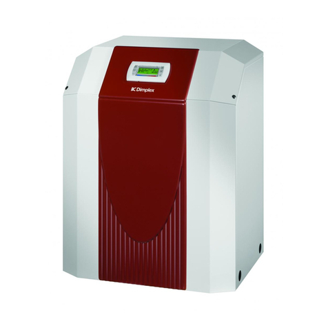
Dimplex
Dimplex SIH 9ME Installation and operating instructions


