iDM iPUMP A 2-7 User manual

iPUMP A 2-7
iPUMP A 3-11
WITH NAVIGATOR 2.0
iDM iPump A/T
THE ENERGYFAMILY
TECHNICAL DOCUMENTATION
INSTALLATION INSTRUCTIONS
HEAT PUMPS FROM AUSTRIA
www.idm-energie.at
812548 Rev.19 - Translation of original instruction
AIR HEAT PUMP WITH
INVERTER-TECHNOLOGY

(C) IDM ENERGIESYSTEME GMBH
2
.
Installation instructions iPump A 2-7, 3-11
2
Contents
1. GENERAL INFORMATION 4
1.1. Standards and directives 4
1.2. Safety instructions 4
1.3. Storage 4
1.4. Installation room 4
1.5. Sound emission 5
1.6. Ice-covering outdoor unit 5
1.7. Installing additional components 5
1.8. Construction drying and screed heating 5
1.9. Cleaning 5
1.10. Servicing and maintenance 5
1.11. Service 5
1.12. Warranty and guarantee 5
1.13. Disposal 5
2. ACOUSTIC EVALUATION 6
3. DESCRIPTION 8
3.1. Intended use 8
3.2. Scope of delivery 8
3.3. Dimensions indoor unit 9
3.4. Connections indoor unit 9
3.5. Dimensions Outdoor unit 10
3.6. Connections Outdoor unit 10
3.7. Technical data 11
3.8. Performance data iPump A 2-7 acc. to EN 14511 13
3.9. Cooling data detailed iPump A 2-7 14
3.10. Filling quantity refrigerant 17
3.11. Maximum heigth difference 17
3.12. Linits of use 18
3.13. Performance data iPump A 3-11 acc. to EN 14511 20
3.14. Cooling data detailed iPump A 3-11 21
3.15. Filling quantity refrigerant 24
3.16. Maximum heigth difference 24
3.17. Limits of use 25
4. TRANSPORT 27
5. DISASSAMBLE THE IPUMP 28
5.1. Connecting the control unit 33
6. ASSEMBLY AND HYDRAULIC INSTALLATION 34
6.1. Assembly of the indoor unit 34
6.2. Replacement of the motor of the switching valve „Heating - hot water“ 36
6.3. Drinking water connection 37
6.4. Assembly of the outdoor unit 37
6.5. Installation variant for the outdoor unit 38
6.6. Place of installation 38

(C) IDM ENERGIESYSTEME GMBH Installation instructions iPump A 2-7, 3-11 3
Contents
All rights reserved for modifications to the technology and design!
6.7. Assembling of the outdoor unit on the concrete base 39
6.8. Earthing of the heat pump system 39
6.9. Condensation run-off 40
6.10. Connection of the condensation run-off 40
6.11. Minimum distances 40
7. CONNECTION OF THE REFRIGERANT CIRCUIT 41
7.1. Connection lines of the refrigerant circuit 41
7.2. Connection of the outdoor unit on refrigerant side 41
7.3. Connection of the indoor unit on refrigerant side 42
7.4. Wall opening 43
7.5. Installation of the refrigerant connection pipes 43
7.6. Important information about the installation of the refrigerant pipes 43
8. ELECTRICAL ASSEMBLY 44
8.1. Electrical power supply 44
8.2. Electrical connection indoor unit 44
8.3. Electrical connection indoor unit 44
8.4. Electrical connection of the outdoor unit 45
8.5. Connection diagram of the electrical module 46
8.6. Connection of the central unit 47
9. COMMISSIONING 48
9.1. Notes for commissioning 48
9.2. Appliance and operation 48
9.3. Faults 48
10. MAGNESIUM PROTECTION ANODE 49
10.1. General 49
10.2. Testing the magnesium protection anode 49
10.3. Exchange of the magnesium protection anode 50
10.4. Installing an external current anode 51
11. HYDRAULIC DIAGRAMS 52
11.1. iPump A with direct circuit for heating and hot water circulation 52
11.2. iPump A with direct heating circuit, hot water circulation and one mixer heating circuit 53
12. HEATING SIDE INSTALLATION 54
13. DECLARATION OF CONFIRMITY, PRODUCT FICHE 55
14. TECHNICAL DOCUMENTATION 58

(C) IDM ENERGIESYSTEME GMBH
1
.
G
e
n
eral i
n
formatio
n
Installation instructions iPump A 2-7, 3-11
4
General information
By purchasing this system you have acquired a
modern and efficient heating system. Ongoing qua-
lity controls and improvements as well as functional
checks at the factory guarantee you technically per-
fect equipment.
Please read through this documentation carefully.
It contains important information for correct
installation and safe and economical operation of
the system.
1.1. Standards and directives
Note for the installation of the heatpump follow all
effective national and international piping- and ins-
tallation rules and the instructions of this Installation
instruction.
Amongst others comparing the following:
- the general effective rules for accident prevention
and safety regulations
- the regulations for environmental protection
- the provisions/regulations of the professional asso-
ciations
- the effective laws, standards, guidelines and regu-
lations e.g. DIN, EN, DVGW, VDI and VDE
- regulations of the local suppliers/supply company
1.2. Safety instructions
Installation and maintenance work can be hazardous
due to high system pressure, high temperatures and
live parts, and may only be carried out by specialist
staff.
Heat pumps may only be installed by competent spe-
cialist staffand commissioned by a customer service
company trained to do so by iDM-Energiesysteme
GmbH.
When working on the heat pump, the system must be
shut-offand secured against re-activation.
In addition, all safety instructions in the relevant do-
cumentation, stickers on the heat pump itself and all
other applicable safety regulations must be observed.
1. General information
1.3. Storage
Heat pump components may not be stored outdoors.
Heat pumps should not be stored in wet rooms or in
potentially dust rooms.
1.4. Installation room
The internal unit of the iPump A should be installed in
a frost-proof room. The Room temperature should be
between 5°C and 25°C.
To minimize vibrations and noises, the heat pump
must be isolate from the building structure. Basically,
the setting up of the heat pump on lightweight design
ceilings must be avoided. In case of a floating floor
screed the screed and the sound damping around the
heat pump have to be omitted.
The installation in wet rooms or in potentially dust or
explosion-endangered rooms is not allowed.
Gas from refrigerants in plant rooms must not escape
into vicinal rooms, stair rooms, courtyards, walks or
into the drainage system of the building. The gas has
to be channelled offsafely.
In case of danger, the plant room has to be evacuated
immediately.
In case a natural ventilation is not possible, a me-
chanical ventilation has to be provided. A mechanical
ventilation has to be equipped with an independent
emergency control outside of the machine room near
the door.
Heat pumps should not be installed in rooms with high
electromagentic influences from other installations.
If the minimum size of the installation room falls below
the required value, the room must be designed as an
machine room according to EN 378!

(C) IDM ENERGIESYSTEME GMBH Installation instructions iPump A 2-7, 3-11 5
Space for customer service telephone
number:_________________________
General instructions on installing the heat
pump.
general information
1.5. Sound emission
The iPump A outdoor unit is very quiet in operation
thanks to the design. It is however important that
the site of the heater is situated as far as possible
from noise-sensitive living areas. This also applies to
refrigerant connection lines between the outside- and
the indoor unit.
Also the boiler room where the indoor unit of the
iPump A is installed should be placed outside of the
noise sensitive living area. The boiler room should be
furnished with a good lockable door.
1.6. Ice-covering outdoor unit
Depending on the weather and outdoor humidity, it
may happen that there will be formed an icy covering
on the protective grids of the heat pump. This effect
is common occuring in nature. This covering must
be removed by the heat pump operator during this
weather periods.
1.7. Installing additional components
The installation of additional components which have
not been tested with the equipment may impair its
function. No liability is accepted and your guarantee
is void in the event of damage caused for this reason.
1.8. Construction drying and screed heating
The heat pump is not designed for the increased heat
requirements when drying out construction work or
heating plaster or screed. This must be covered by
equipment to be provided by the customer if required.
1.9. Cleaning
If necessary, the internal and the outdoor unit of the
iPump A can be cleaned with a damp cloth. The use
of cleaning agents is not recommended.
1.10. Servicing and maintenance
Regular maintenance control and servicing of all
system components guarantee its safe and econo-
mical operation in the long term. To achieve this, we
recommend a maintenance contract with the relevant
customer service company.
Only original spare parts which meet the requirements
of iDM may be used!
1.11. Service
For technical information please contact your relevant
iDM customer service department.
1.12. Warranty and guarantee
Warranty and guarantee conditions are included
in the purchased documents. For questions please
contact your relevant customer service department.
1.13. Disposal
Heatpumps are electrical equipment made from
high valuable materials, which are not allowed to be
disposed like normal household garbage, but have to
be disposed professional and proper according the
regulations of the local authorities.
A non-proper disposal can cause, apart from sanc-
tions for the violator, environmental damages and
harm for your health.
This device is characterized according to the euro-
pean directive 2012/19/EU on waste electrical and
electronic equipment (Waste electrical and electronic
equipment - WEEE). The guideline provides the
framework for an EU-wide return and recycling of old
equipment.
Dispose the device properly and do not damage the
pipes of the refrigerant circuit.
Important information on installing and
operating the heat pump. It is essential that
this information is observed!
General instructions on operating the heat
pump.
(C) IDM ENERGIESYSTEME GMBH
2
.
A
coustic e
v
aluatio
n
Installation instructions iPump A 2-7, 3-11
6
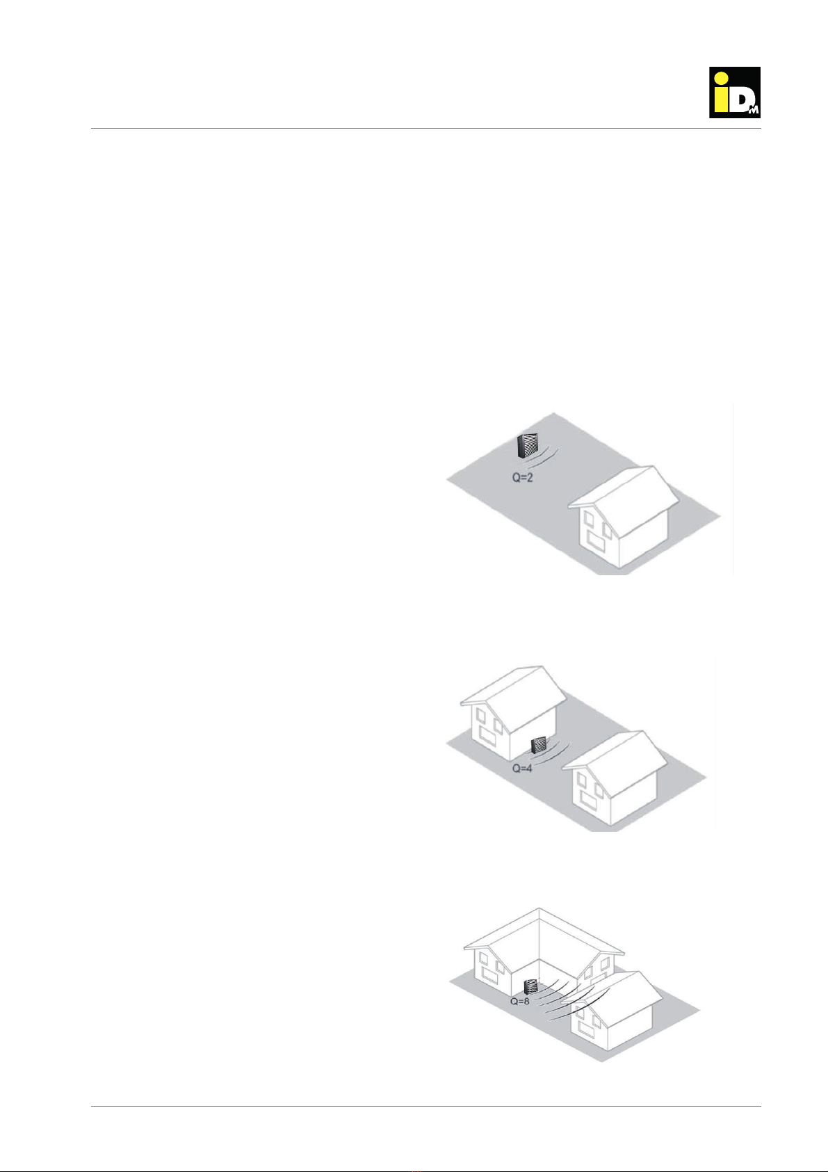
Version 1: Spherical spreading into 1/2 space (free
standing installation)
Version 2: Spherical spreading into 1/4 space
(installation next to facade)
Version 3: Spherical spreading into 1/8 space:
acoustic evaluation
2. Acoustic evaluation
Sound power level
The sound power is the sound energy per second
emitted of a noise source. The sound power level is
specific to the source of sound, independent of dis-
tance and direction and enables an easy comparison
of different sound emitting devices. The sound power
can only be determined via mathematical calculation
according to international standards of the series
ISO 3740 - based on sound pressure level measure-
ments - as well as ISO 9614, which is based on the
measurement of sound intensity. The sound power
level of the heat pumps can be found in the technical
specifications.
Sound pressure level
In contrast to the sound power level, the sound pres-
sure level, which is caused by a noise source can be
measured. The measured sound pressure is depen-
dent on the distance from the noise source and the
receiver location (geometrical divergence) as well as
the local conditions. As the sound pressure level is a
measure of the loudness of noise sensed by humans,
the legislation defines limit values, that must not be
exceeded.
Sound-propagation-outdoor
With increasing distance from a point noise source,
the sound power is distributed on an increasing area
due to spherical spreading. Therefore, the sound
pressure level is continuously decreasing with in-
creasing distance from the noise source to receiver
location. Doubling the distance leads to a reduction of
the sound pressure level of 6 dB(A). Besides the di-
stance from the installation site of the heat pump the
sound, the installation situation and local conditions
also have significant impact on the resulting sound
pressure level at the relevant place of immission.
Major factors of influence are:
- sound attenuation by massive barriers e.g. buil-
dings, walls or different terrain.
-reflection on acoustically hard ground e.g. glass
facade and stone surfaces
- attenuation due to sound absorbing porous sur-
faces e.g. grass, trees
- reinforcement/reduction of by wind speed/direction
Noise immission
The noise caused by an source at a certain place is
expressed as Immission, the corresponding sound
pressure level is called Immission level.The immissi-
on level at the relevant place of immission can either
be calculated with the iDM-sound calculator.
The calculation of the sound pressure level shall be
calculated by means of the following examples for
typical installation situations of the outdoor unit.
Source: bwp-Leitfaden-Schall
Source: bwp-Leitfaden-Schall
Source: bwp-Leitfaden-Schall

(C) IDM ENERGIESYSTEME GMBH Installation instructions iPump A 2-7, 3-11 7
acoustic evaluation
Relevant place of immission
The sound immission have to be determined 0.5 m
in the middle in front of the open window (outside the
building) of the most affected rooms, which need par-
ticular protection. According DIN 4109:1989 rooms
needing particular protection are:
- Living- and bed rooms
- Children rooms
- Work spaces / offices
- Classrooms / seminar rooms
Rating level Lr .
The rating level corresponds to an equivalent conti-
nuous sound pressure level associated with a specific
period. The rating level is determined for both rating
periods „day“ (6 am-10 pm) and „night“ (10 pm-6 am)
separately. The operation time of the heat pump has
particular impact on the resulting equivalent conti-
nuous sound pressure level. Reducing the operation
time from 16 h per day to 4 h per day the rating level
is reduced by 6 dB(A).
But the equivalent continuous sound pressure level
alone is not sufficient in order to determine the distur-
bing effect of noise. In general noise is perceived very
disruptive, if individual tones are clearly discernable
or the noise is irregular (impulsiveness). These noise
characteristics will be taken into account by applying
a surcharge. Additionally, daytimes with increased
sensitivity are taken into consideration. According the
„TA Lärm“ the following corrections are applied:
Information incorporation 3 or 6 dB(A)
Impulsiveness 0,3 or 6 dB(A)
Daytimes with increased
sensitivity 6 dB(A)
The rating level Lrshall be obtained by summing the
calculated immission level and the applied correc-
tions of the specific periods.
Finally, the determined rating level can be compared
with legal limit values (e.g. „TA Lärm“).
Standard Immission Values (SIV) - relevant place of
immission outside the building:
Territory SIV-day SIV-night
Industrial area 70 dB(A) 70 dB(A)
Business park,
commercial areas 65 dB(A) 50 dB(A)
Village areas and mixed
areas 60 dB(A 45 dB(A)
Settlement area 55 dB(A) 40 dB(A)
Residential area 50 dB(A) 35 dB(A)
Spa area, hospitals 45 dB(A) 35 dB(A)
In case of sound propagation inside buildings or
structure-borne sound transmission the Standard
Immission Values for the rating level of rooms nee-
ding particular protection are as following:
SIV-day: 35 dB(A)
SIV-night: 25 dB(A)
For the calculation of the rating level according „TA
Lärm“ a calculation tool is provided at the hom page:
http://www.idm-energie.com
Tips for installation of heat pumps
-
Sound reflections areas should be kept as low as
possible
- The installation on acoustically hard ground and
areas with depression in the terrain should be avo-
ided
- The distance from the heat pump and the relevant
place of immission should be as big as possible
- In case of outdoor installation the blow out of air
in direction to the neighbour or relevant receiver
location should be avoided
- The airflow should not be blown directly against
walls as sound reflections lead to increased sound
pressure levels accordingly

(C) IDM ENERGIESYSTEME GMBH
3
.
D
escriptio
n
Installation instructions iPump A 2-7, 3-11
8
Description
Montage Heizungsseitig
3. Description
iPump A are compact air-water heat pump with a sc-
roll capsule compressor with inverter technology and
400 V or 230 V power supply.
The Indoor unit of the iPump A includes the conden-
ser, a high efficiency loading pump, the switching
valve for heating-/domestic hot water, an immersion
heater, a 200 l DHW storage tank and a sensor set.
The outdoor unit includes the evaporator and the
axial ventilator.
The microprocessor controller NAVIGATOR 2.0 en-
sures efficient operation of the heat pump.
The heat pump system is controlled as needed and is
equipped with a variety of monitoring-, security- and
reporting functions.
By default, an unregulated and a regulated heating
circuit can be controlled.
The microprocessor controller NAVIGATOR 2.0 pro-
vides a variety of additional applications, e.g. Smart
Grid, remote control or operation via smartphones.
The heat meter is integrated by default.
A colored 7“ touch display simplifies the operation of
the heat pump. The display can be removed from the
housing of the iPump A and can be placed separately,
e.g. in the living room.
In order to simplify the transport into the heating
room, the iPump A can be split.
The connections for the refrigerating pipes are optio-
nal on the right or left side of the heat pump.
The connections for heating- and hot water lines are
at the top, as well as the LAN-connection, the cable
inlet for the sensors and the optional connection for
the circulation.
The lower the maximum flow temperature
is set, the higher is the efficiency of the
heat pump.
The electrical lines and refrigerant con-
nection pipes between the indoor and out-
door units are not in the scope of delivery.
The parts are available as accessories
and must be connected according to the
technical specifications.
3.1. Intended use
For monovalent heating and cooling of single- and
multiple dwellings with the heat source air. In this
case, the building should be equipped with a low tem-
perature heating systems (e.g. underfloor heating,
wall heating, low temperature radiator heating). The
heat pump may only be used for domestic and not for
purely commercial operation!
The iPump A is working with the safety refrigerant
R410A, that circulates in an closed circuit. When ins-
talled and commissioned properly, meaning that there
is no environmental impact.
3.2. Scope of delivery
Outdoor unit iPump A
- Housing in sheet metal covering, powder-coated
- Housing optional with cladding panels
- Fin evaporator
- Electronic expansion valve
- Axial ventilator with Flow-Grid
- Mounting kit for the installation of the outdoor unit-
consists of:
4 pcs. threaded bolt M12 x 210 mm
8 pcs. hexagonal nuts M12
8 pcs. washers M12
Indoor unit iPump A
- Heat pump with Scroll-compressor with inverter
technology
- Inverter with patented CIC-Technology
- Copper soldered stainless steel plate heat ex-
changer as condenser
- Refrigerant collector
- Refrigerant dryer
- Refrigerant inspection glass
- Electronic expansion valve
- Electronic high pressure and low-pressure limiter
- Switching valve heating/domestic hot water
- Integrated A-Label loading pump
- Colored 7“ Touch display with NAVIGATOR 2.0
- Stable base frame
- Cladding, insulated against heat and noise
- Sensor package
(C) IDM ENERGIESYSTEME GMBH Installation instructions iPump A 2-7, 3-11 9
description
Monta
g
e Heizun
g
sseiti
g
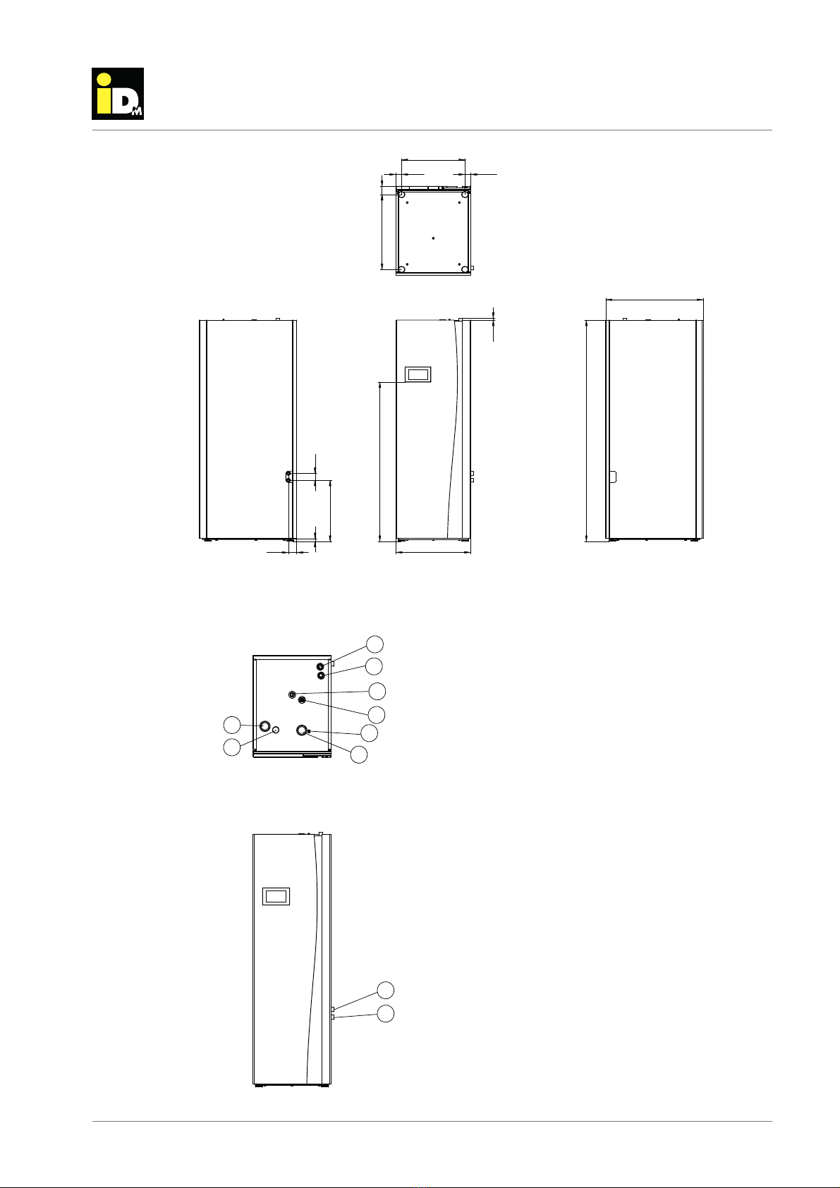
Bottom view
Side view / right Front view
Side view / left
3.3. Dimensions indoor unit
9
10
2
1
3
4
5
6
7
8
Bottom view
Front view
1 Heating supply 1“
2 Heating return 1“
3 Hot water connection 3/4“
4 Cold water connection 3/4“
5 Inlet cables of sensors
6 LAN-Connection
7 Circulation connection 3/4“
8 Cable inlet main current
9 Refrigerant pipe - liquid line 12 mm
10 Refrigerant pipe - hot gas line 16 mm
3.4. Connections indoor unit

(C) IDM ENERGIESYSTEME GMBH
3
.
D
escriptio
n
Installation instructions iPump A 2-7, 3-11
10
Description
Montage Heizungsseitig
Front view Side view / left
Inlet side Outlet side
3.5. Dimensions Outdoor unit
Refrigerant pipe connections
Ø10 mm and Ø12 mm
resp. Ø12 mm und Ø16 mm
Condensation
drain 1“
Outlet side
Inlet side
3.6. Connections Outdoor unit (View from below)

(C) IDM ENERGIESYSTEME GMBH Installation instructions iPump A 2-7, 3-11 11
description
Monta
g
e Heizun
g
sseiti
g
Heat pump type iPump A 2-7 iPump A 3-11
Model 230 V 400 V
230 V
Space heating water energy efficiency class - 35°C 55°C 35°C 55°C
Energy efficiency class water heating -
Unit
Performance data acc. to EN 14511 at nominal speed
Heat output at A2°C/W35°C kW 3.90 5.92
Power consumption at A2°C/W35°C kW 0.88 1.35
COP at A2°C/W35°C - 4.42 4.37
Cooling capacity at A35°C/W18°C kW 4.95 7.80
Power consumption at A35°C/W18°C kW 1.03 1.81
EER at A35°C/W18°C - 4.80 4.32
Sound emission1
Sound power level nominal according to EN 12102 indoor unit dB(A) 42 45
Sound power level maximum according to EN 12102 indoor unit dB(A) 52 48
Sound power level nominal according to EN 12102 outdoor unit dB(A) 46 50
Sound power level maximum according to EN 12102 outdoor unit dB(A) 49 53
Sound reduced operation outdoor unit (reduced power) dB(A) 46 49
The sound pressure level can be calculated with
the iDM-sound calculation tool
Dimensions indoor unit
Height / Width / Depth mm 1950 / 600 / 786
Tilted height mm 2150 2150
Weight kg 251 270
Minimum size of installation room2(with standard filling) m³ 7.27 9.32
Dimensions outdoor unit
Height / Width / Depth mm 1180 / 1110 / 745
Weight kg 110 113
Hot water tank
Volume of hot water storage tank l 192
Maximum storage temperature °C 55
Maximum storage temperature with electrical heating unit °C 75
Max. single draw of hot water at 46°C tapping temp. - Heat pump3l 260
Max. single draw of hot water at 46°C tapping temp. - Electrical heater4l 356
Max. single draw of hot water at 40°C tapping temp. - Heat pump3l 315
Max. single draw of hot water at 40°C tapping temp. - Electrical heater4l 432
Max. operating pressure heating side bar 3
Max. operating pressure domestic hot water bar 10
Hot water connection R 3/4“
Cold water connection R 3/4“
3.7. Technical data
A+++ A++
A
A+++ A+++
A

(C) IDM ENERGIESYSTEME GMBH
3
.
D
escriptio
n
Installation instructions iPump A 2-7, 3-11
12
Description
Montage Heizungsseitig
Heat pump type iPump A 2-7 iPump A 3-11
Unit
Maximum heating supply temperature6°C 62
Regrigerant - R410A
Quantity of refrigerant (up to 6 m) kg 3.2 4.1
GWP51924
Compressor oil - FV50S EMKARATE
RL 32-3MAF
Quantity of compressor oil l 0.35 0.99
Compressor stages - 1-stage modulated
Air volume outdoor unit
(A7°C/W35°C at nominal speed6)m³/h 2500 3600
Integrated loading pump Wilo Yonos Para RS15/7.5
Nominal flow rate heating water (A7°C/W35°C nom. speed) m³/h 0.8 1.2
Free residual pressure loading pump (A7°C/W35°C max. speed*) kPa 65 66
Free residual pressure loading pump (A7°C/W35°C nom. speed*) kPa 36 40
Pressure loss heating side (A7°C/W35°C) at nominal output7kPa 9 9
Connection dimension
Heating supply / -return R1“
Refrigerant pipe - Hot gas line mm Ø12.7x0.8(1/2“) 16
Refrigerant pipe - Liquid line mm Ø9.53x0.8 (3/8“) 12
Maximum length of split-piping between indoor- and outdoor unit m 20 m /
max. height difference 10 m4
Electrical data
Electrical power supply compressor V / Hz 1~230 / 50 1~230 / 3~400
Electrical power supply heating unit V / Hz 3~400 / 50 3~400 / 50
Electrical power supply controller V / Hz 1~230 / 50 1~230/ 50
Maximum operating current of compressor A 15.8 9 / 24
Maximum operating current of ventilator A 0.24 0.5
Maximum power consumption ventilator W 56 113
Performance factor cos phi 1 0.98
Maximum power consumption heating unit A 26 13.04
Starting current A < 15.8 < 9
Performance factor 1~230 V cos phi 0.99 0.97/0.99
Fuse of main power supply A C/K 16 C/K 13 / 25
Fuse of control main supply A B/Z 13 B/Z 13
Fuse electrical heater A B/Z 13 B/Z 13
1Uncertainty of measurement ± 1,5 dB(A)
2If the size of the installation room is lower then the required minimum size, the room must be performed as an engine room according to EN 378
312°C cold water temperature / 58°C buffer temperature
412°C cold water temperature / 75°C buffer temperature
5According to the 5th IPPC Status Report
6The 62°C refers to the maximum heat pump flow temperature. The resulting lower hot water temperature must be checked in relation to compliance with the drinking water
ordinance.
7at 80% pump capacity
*Adjustment min. speed loading pump 60%, max. 100%
(C) IDM ENERGIESYSTEME GMBH Installation instructions iPump A 2-7, 3-11 13
description
Monta
g
e Heizun
g
sseiti
g
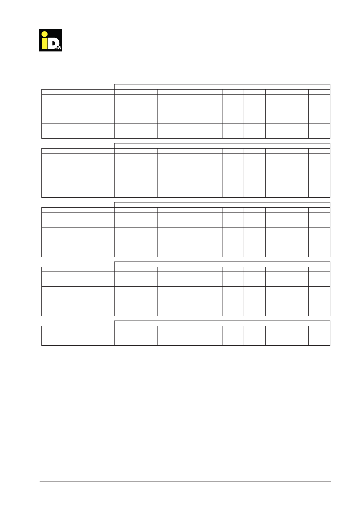
3.8. Performance data iPump A 2-7 acc. to EN 14511
20 15 12 10 7 2 -7 -10 -15 -18
4404675445967558739389879891005
205 205 206 204 202 200 187 184 173 171
258270295319378431459480482490
,ĞĂƚĐĂƉĂĐŝƚLJ [kW]
WŽǁĞƌĐŽŶƐƵŵƉƚŝŽŶ [kW]
COP
20322026129639045,4492506530540
083 083 083 087 0,87 088 087 083 081 079
256272313341442519566610636653
203200220200206223244260262270
041 040 040 041 043 047 060 070 075 079
256268312335438524591645
654
660
20 15 12 10 7 2 -7 -10 -15 -18
386415519570707833896941946963
248 246 247 244 241 216 219 213 214 210
389 384 381 367 346 327 260 244 194 184
200200241270362421459483487501
106 106 106 107 107 107 101 099 094 105
473 459 454 429 392 340 266 244 212 190
200199203200200200216231237254
053 053 054 054 055 067 079 086 094 105
190212235252297363400431443481
20 15 12 10 7 2 -7 -10 -15 -18
433426475518670791848908879905
295 294 297 285 280 271 248 250 251 281
306 299 306 297 282 247 209 190 170 154
200200228257346411445465471486
119 119 120 121 121 120 115 113 117 131
408 394 389 367 340 289 224 202 171 153
200182192173183202221239233243
059 058 058 058 059 064 079 095 108 131
153168201220286343383411405413
20 15 12 10 7 2 -7 -10 -15 -18
242299452509653795856900904926
283 282 283 280 276 243 258 254 251 247
327 320 318 306 288 269 197 178 119 098
200200215244329402430448
455472
129 128 129 131 128 125 118 116 129 142
367 354 348 329 313 263 206 185 155 141
200200200200
200200203210215231
070 069 069 071 075 083 103 108 129 142
141155185194242267285306313329
20 15 12 10 7 2 -7 -10 -15 -18
200200197226305389409424433452
143 141 142 145 138 132 122 120 146 157
316 307 299 282 282 231 185 164 137 127
MaxMIN MaxEKDMIN MINMaxMIN
KƵƚĚŽŽƌƚĞŵƉĞƌĂƚƵƌĞΣ
&ůŽǁƚĞŵƉĞƌĂƚƵƌĞtϯϱΣ
MAX
,ĞĂƚĐĂƉĂĐŝƚLJ [kW]
WŽǁĞƌĐŽŶƐƵŵƉƚŝŽŶ [kW]
COP
,ĞĂƚĐĂƉĂĐŝƚLJ [kW]
WŽǁĞƌĐŽŶƐƵŵƉƚŝŽŶ [kW]
COP
,ĞĂƚĐĂƉĂĐŝƚLJ [kW]
WŽǁĞƌĐŽŶƐƵŵƉƚŝŽŶ [kW]
COP
,ĞĂƚĐĂƉĂĐŝƚLJ [kW]
WŽǁĞƌĐŽŶƐƵŵƉƚŝŽŶ [kW]
COP
,ĞĂƚĐĂƉĂĐŝƚLJ [kW]
WŽǁĞƌĐŽŶƐƵŵƉƚŝŽŶ [kW]
COP
,ĞĂƚĐĂƉĂĐŝƚLJ [kW]
WŽǁĞƌĐŽŶƐƵŵƉƚŝŽŶ [kW]
COP
,ĞĂƚĐĂƉĂĐŝƚLJ [kW]
WŽǁĞƌĐŽŶƐƵŵƉƚŝŽŶ [kW]
COP
,ĞĂƚĐĂƉĂĐŝƚLJ [kW]
WŽǁĞƌĐŽŶƐƵŵƉƚŝŽŶ [kW]
COP
,ĞĂƚĐĂƉĂĐŝƚLJ [kW]
WŽǁĞƌĐŽŶƐƵŵƉƚŝŽŶ [kW]
COP
,ĞĂƚĐĂƉĂĐŝƚLJ [kW]
WŽǁĞƌĐŽŶƐƵŵƉƚŝŽŶ [kW]
COP
,ĞĂƚĐĂƉĂĐŝƚLJ [kW]
WŽǁĞƌĐŽŶƐƵŵƉƚŝŽŶ [kW]
COP
,ĞĂƚĐĂƉĂĐŝƚLJ [kW]
WŽǁĞƌĐŽŶƐƵŵƉƚŝŽŶ [kW]
COP
EKDEKD EKD
EKD
&ůŽǁƚĞŵƉĞƌĂƚƵƌĞtϰϱΣ
&ůŽǁƚĞŵƉĞƌĂƚƵƌĞtϱϬΣ
&ůŽǁƚĞŵƉĞƌĂƚƵƌĞtϱϱΣ
&ůŽǁƚĞŵƉĞƌĂƚƵƌĞtϲϮΣ
KƵƚĚŽŽƌƚĞŵƉĞƌĂƚƵƌĞΣ
KƵƚĚŽŽƌƚĞŵƉĞƌĂƚƵƌĞΣ
KƵƚĚŽŽƌƚĞŵƉĞƌĂƚƵƌĞΣ
KƵƚĚŽŽƌƚĞŵƉĞƌĂƚƵƌĞΣ
(C) IDM ENERGIESYSTEME GMBH
3
.
D
escriptio
n
Installation instructions iPump A 2-7, 3-11
14
Description
Montage Heizungsseitig
3.9. Cooling data detailed iPump A 2-7
To guarantee a correct cooling mode, when working with unregulated direct-heating circles (without cooling
buffer) following 3 requirements have to be fulfilled.
1. To ensure the minimum volume of heating site, appropriate zones have to remain open all the time.
Minimum volume 54 lt.
2. To ensure the minimum flow rate of heating site, appropriate zones have to remain open all the time.
Minimum flow rate 0.72 m³/h
3. To ensure the minimum cooling output rate of distribution system, appropriate zones have to remain open
all the time. The minimum cooling output rate is 70 % of the minimum cooling output power of the heat-
pump at A35°C/W18°C. Minimum cooling consumption 1.75 kW
All 3 requirements must be fulfilled independently. This is possible via the Navigator Pro. The entire distribution
system has to fulfill the 3 mentioned requirements. To ensure a large cooling demand, the cooling limit has to
be set as high as possible.
40 35 30 25 20 15
ϴϬϴ ϴϴϲ ϵϱϱ 1018 1079 ϭϭϮϲ
308 279 255 233 212 199
$PPMJOHDBQBDJUZ [kW]
1PXFSDPOTVNQUJPO [kW]
EER ϮϲϮ ϯϭϳ ϯϳϱ 436 508 567
459 495 563 611 651 685
106 103 086 076 064 052
$PPMJOHDBQBDJUZ [kW]
1PXFSDPOTVNQUJPO [kW]
EER 433 480 653 809 1016 1325
259 290 308 323 331 338
051 043 036 029 025 020
$PPMJOHDBQBDJUZ [kW]
1PXFSDPOTVNQUJPO [kW]
EER 506 679 861 1119 1348 1654
40 35 30 25 20 15
684 749 804 866 917 968
282 258 238 218 199 182
$PPMJOHDBQBDJUZ [kW]
1PXFSDPOTVNQUJPO[kW]
EER 243 290 337 397 461 531
403 431 475 512 533 571
113 103 090 080 068 057
$PPMJOHDBQBDJUZ [kW]
1PXFSDPOTVNQUJPO [kW]
EER 358 418 528 641 782 1007
220 230 247 263 279 283
057 045 039 032 026 021
$PPMJOHDBQBDJUZ [kW]
1PXFSDPOTVNQUJPO [kW]
EER 385 514 638 810 1055 1364
40 35 30 25 20 15
577 633 682 728 772 814
266 244 225 206 188 171
$PPMJOHDBQBDJUZ [kW]
1PXFSDPOTVNQUJPO [kW]
EER 217 260 303 353 411 475
337 376 400 425 451 471
114 101 090 080 070 060
$PPMJOHDBQBDJUZ [kW]
1PXFSDPOTVNQUJPO [kW]
EER 296 372 444 532 644 783
200 201 205 211 224 242
065 053 047 036 030 024
$PPMJOHDBQBDJUZ [kW]
1PXFSDPOTVNQUJPO[kW]
EER 306 379 440 593 753 1012
'MPXUFNQFSBUVSFBUW7¡$
MAX
N0.
MIN
0VUEPPStemperaturF[°C]
'MPXUFNQFSBUVSFBUW12¡$
MAX
N0.
MIN
0VUEPPStemperaturF[°C]
0VUEPPStemperaturF[°C]
'MPXUFNQFSBUVSFBUW18¡$
MAX
N0.
MIN

(C) IDM ENERGIESYSTEME GMBH Installation instructions iPump A 2-7, 3-11 15
description
Monta
g
e Heizun
g
sseiti
g
Heating output iPump A 2-7 at flow temperature 35°C
Heating output iPump A 2-7 at flow temperature 45°C
Ϭ
Ϯ
ϰ
ϲ
ϴ
ϭϬ
ϭϮ
ͲϮϬ Ͳϭϱ ͲϭϬ Ͳϱ Ϭ ϱ ϭϬ ϭϱ ϮϬ
HeDWFDSDFLW\ [kW]
2XWGRRUtemperaturH[°C]
Dy
EKD
D/E
Ϭ
Ϯ
ϰ
ϲ
ϴ
ϭϬ
ϭϮ
ͲϮϬ Ͳϭϱ ͲϭϬ Ͳϱ Ϭ ϱ ϭϬ ϭϱ ϮϬ
HeDWFDSDFLW\ [kW]
2XWGRRUtemperaturH[°C]
DĂdž
EKD
D/E

(C) IDM ENERGIESYSTEME GMBH
3
.
D
escriptio
n
Installation instructions iPump A 2-7, 3-11
16
Description
Montage Heizungsseitig
Heating output iPump A 2-7 at flow temperature 55°C
Heating output iPump A 2-7 at nominal speed
Ϭ
ϭ
Ϯ
ϯ
ϰ
ϱ
ϲ
ϳ
ϴ
ϵ
ϭϬ
ͲϮϬ Ͳϭϱ ͲϭϬ Ͳϱ Ϭ ϱ ϭϬ ϭϱ ϮϬ
HeDWFDSDFLW\ [kW]
2XWGRRUtemperaturH[°C]
DĂdž
EKD
D/E
ϭ
Ϯ
ϯ
ϰ
ϱ
ͲϮϬ Ͳϭϱ ͲϭϬ Ͳϱ Ϭ ϱ ϭϬ ϭϱ ϮϬ Ϯϱ
HeDWFDSDFLW\ [kW]
2XWGRRUtemperaturH[°C]
tϯϱ
tϰϱ
tϱϱ
tϱϬ
tϲϬ
(C) IDM ENERGIESYSTEME GMBH Installation instructions iPump A 2-7, 3-11 17
description
Monta
g
e Heizun
g
sseiti
g
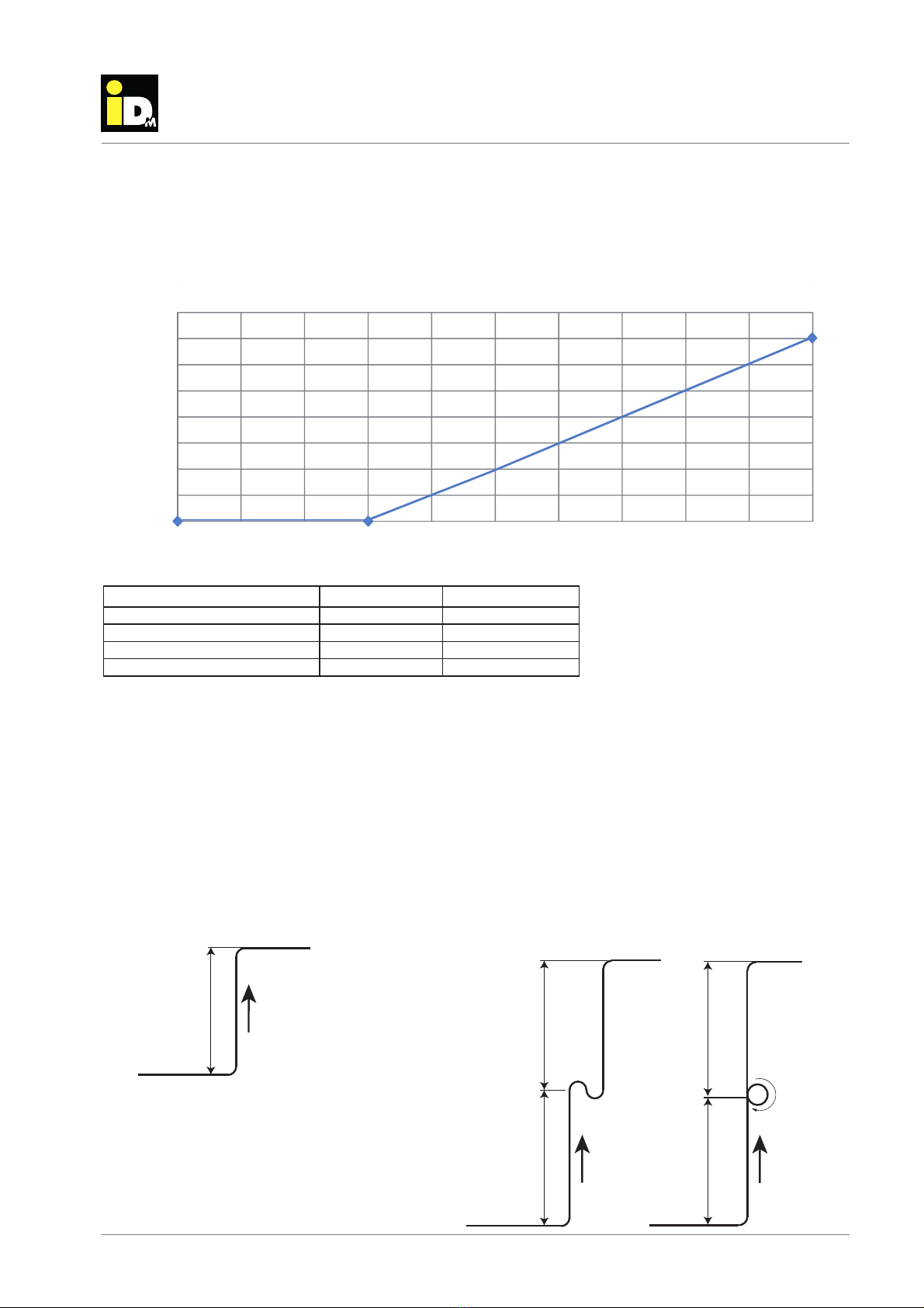
3.10. Filling quantity refrigerant
The iPump A 2-7 is pre-filled with refrigerant. Up to a distance of 6 m between indoor unit and outdoor unit no
refrigerant no additional needs to be refilled. For pipe length more than 6 m, the following refrigerant quantities
must be refilled.
3.11. Maximum heigth difference
If the height difference between the indoor unit and outdoor unit is lower than 5 m no oil elevation arc must be
installed before the inclination. In case of a higher height difference the installation must be done after 5 m. The
oil elevation arc must be installed by a certificated service technician. Whether the indoor unit or the outdoor
unit is higher, does not matter. The maximum height difference between indoor unit and outdoor unit is 10 m.
0
0.1
0.2
0.3
0.4
0.5
0.6
0.7
0.8
0 2 4 6 8 10 12 14 16 18 20
ZĞͲĨŝůůƋƵĂŶƚŝƚLJ in [kg]
Wŝ
Ɖ
ĞůĞŶ
Ő
ƚŚŝŶŽŶĞĚŝƌĞĐƚŝŽŶ
[
m
]
ZĞĨƌŝŐĞƌĂŶƚƌĞͲĨŝůůƋƵĂŶƚŝƚLJ iPump A 2-7
WŝƉĞůĞŶŐƚŚŝŶŽŶĞĚŝƌĞĐƚŝŽŶ[m] ZĞĨƌŝŐĞƌĂŶƚƋƵĂŶƚŝƚLJ[kg] ZĞͲĨŝůůƋƵĂŶƚŝƚLJ [kg]
032Ϭ6
02Ϭ34Ϭ
01
04536551
07Ϭ39Ϭ02
max 5 m
<5 m max 5 m
max 5 m max 5 m
Height difference lower than 5 m Height difference more than 5 m
Version 2Version 1

(C) IDM ENERGIESYSTEME GMBH
3
.
D
escriptio
n
Installation instructions iPump A 2-7, 3-11
18
Description
Montage Heizungsseitig
3.12. Linits of use
The heating of other fluids as heating water is not permitted with the iPump A 2-7 (for heating water quality,
see page 51). Heat pumps are by nature subjects to limits of use regarding of pressure and temperature (see
diagram). It is not permissible to operate the iPump A 2-7 outside these limits.
Note:
The following safety devices are included to protect the heat pump against faults:
- High pressure presostat
- Maximum flow temperature limitation with automatic reset via the NAVIGATOR control
- Starting current limiter via inverter technology and performance adjustment
-20 -10 0 5 10 20 30 35 40
30
40
50
60
20
[°C]
[°C]
R410A
62
42
Outdoor temperature
Flow temperature
iPump A 2-7 - Heating
Heating
The maximum heat pump flow temperature is the highest temperature that the heat pump can
produce (depending on the heat source temperature) and is then switched off at this value. Due to
the hydraulic spread over the heat pump and the control-related switching hysteresis, it is not pos-
sible to reach this temperature in the heating circuit or in the water heater. The maximum possible
management temperature depends on the hydraulic design and the configuration, and is at least 5
K below the maximum heat pump flow temperature.

(C) IDM ENERGIESYSTEME GMBH Installation instructions iPump A 2-7, 3-11 19
description
Monta
g
e Heizun
g
sseiti
g
10 15 20 25 30 35
10
15
20
25
30
5
[°C]
R410A
[°C]
40 45
0
Flow temperature
Outdoor temperature
iPump A 2-7 - Cooling
Cooling
The minimum heat pump flow temperature is the lowest temperature that the heat pump can produce
(depending on the heat source temperature) and is then switched off at this value. Due to the hydrau-
lic spread across the heat pump, the control-related switching hysteresis and the humidity-dependent
dew point, it is not possible to reach this temperature in the cooling circuit. The lowest possible
management temperature depends on the hydraulic design, the configuration and the actual dew
point on site and is at least 5 K above the minimum heat pump flow temperature.
The maximum power of the iPump A can be limited with the NAVIGATOR 2.0 controller.

(C) IDM ENERGIESYSTEME GMBH
3
.
D
escriptio
n
Installation instructions iPump A 2-7, 3-11
20
Description
Montage Heizungsseitig
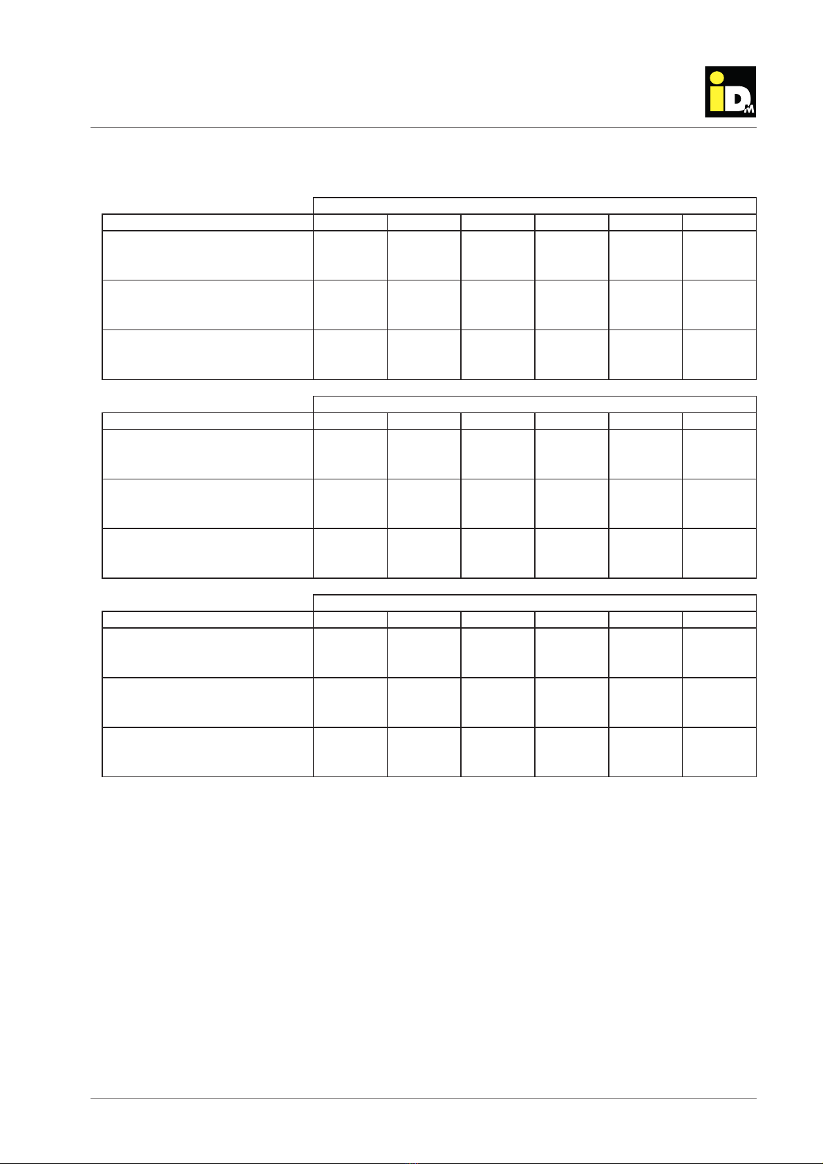
3.13. Performance data iPump A 3-11 acc. to EN 14511
20 15 12 10 7 2 -7 -10 -15 -18
Heat output 08.670.813.900.0102.0105.2108.2108.2108.2108.21]Wk[
Power intake 34.306.386.327.304.351.379.258.295.203.2]Wk[
89.1
42.235.296.200.379.313.405.459.465.5POC
Heat output 02.314.300.424.429.597.692.708.703.809.8]Wk[
Power intake 43.103.163.153.1
53.133.153.153.114.114.1]Wk[
83.226.259.282.373.401.505.587.509.503.6POC
Heat output 08.208.208.208.208.209.202.34
5.340.406.4]Wk[
Power intake 42.141.110.149.097.036.056.096.027.047.0]
Wk[
52.254.277.279.265.336.409.431.506.502.6P
OC
20 15 12 10 7 2 -7 -10 -15 -18
Heat output 06.608.767.817.998.902.2104.2106.2107.2107.21]Wk[
Power intake 89.349.320.411.421.400.448.365.371.307.2]Wk[
COP 4.70 4.01 3.54 3.23 3.05 2.40 2.36 2.18 1.98 1.66
Heat output 11.3
92.368.362.405.534.670.773.758.704.8]Wk[
Power intake 65.165.106.116.146.136.106.106.195.155.1]Wk[
COP 5.41 4.95 4.61 4.41 3.95 3.36 2.64 2.41 2.11 1.99
Heizleistung 08.208.208.208
.208.208.208.212.308.324.4]Wk[
Power intake 42.239.165.193.180.167.086.017.087.038.0]Wk[
52.1
54.108.110.206.207.311
.405.458.403.5POC
20 15 12 10 7 2 -7 -10 -15 -18
Heat output 10.311.337.321.413.552.628.611.785.712.8]Wk[
Power intake 66.156.117.107.157.177.167.147.117.107.1]Wk[
COP 4.84 4.42 4.08 3.88 3.53 3.04 2.42 2.18 1.89 1.81
20 15 12 10 7 2 -7 -10 -15 -18
Heat output 84.803.907.910.2101.2153.2106.2106.21]Wk[ --
Power intake 02.493.438.426.404.414.400.423.3]Wk[ --
COP 3.80 3.15 2.80 2.75 2.60 2.01 2.12 2.02 --
Heat output 06.389.311.570.66
5.658.613.710.8]Wk[ --
Power intake 28.118.198.169.169.139.188.188.1]Wk[ --
COP 4.26 3.89 3.55 3.34 3.10 2.71 2.20 1.98 --
Heat output 08.208.208.208.208.209.205.308.3]Wk[ --
Power intake 62
.251.211.150.109.038.058.008.0]Wk[ --
42.103.135.276.221.315.301.447.4POC --
20 15 12 10 7 2 -7 -10 -15 -18
Heat output 08.456.523.616.620.767
.
7]Wk[ ----
Power intake 62.263.214.263.212.291,2]Wk[ ----
COP 3,55 3.18 2.80 2.62 2.39 2.12 ----
&ůŽǁƚĞŵƉĞƌĂƚƵƌĞW45Σ
NOMINAL
&ůŽǁƚĞŵƉĞƌĂƚƵƌĞW55Σ
&ůŽǁƚĞŵƉĞƌĂƚƵƌĞW50Σ
NOMINAL MAXMINNOMINAL MAX
KƵƚĚŽŽƌtemperature [°C]
KƵƚĚŽŽƌtemperature [°C]
&ůŽǁƚĞŵƉĞƌĂƚƵƌĞW35Σ
MAXNOMINALMIN
KƵƚĚŽŽƌtemperature[°C]
MIN
&ůŽǁƚĞŵƉĞƌĂƚƵƌĞW62Σ
NOMINAL
KƵƚĚŽŽƌtemperature ŝŶ[°C]
KƵƚĚŽŽƌtemperature [°C]
This manual suits for next models
1
Table of contents
Popular Water Pump manuals by other brands


Seaflo
Seaflo 51 Series manual

Kamoer
Kamoer X1 PRO T quick start guide

Grundfos
Grundfos Unilift AP12 Installation and operating instructions

DIVERSITECH
DIVERSITECH CP-16 Installation and safety instructions

Neptun
Neptun NCSP-E 35 Original operating instructions

Grundfos
Grundfos CRE Series Installation and operating instruction


