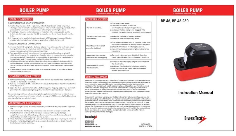
DIVERSITECH CP-16 Manual
Other DIVERSITECH Water Pump manuals
DIVERSITECH
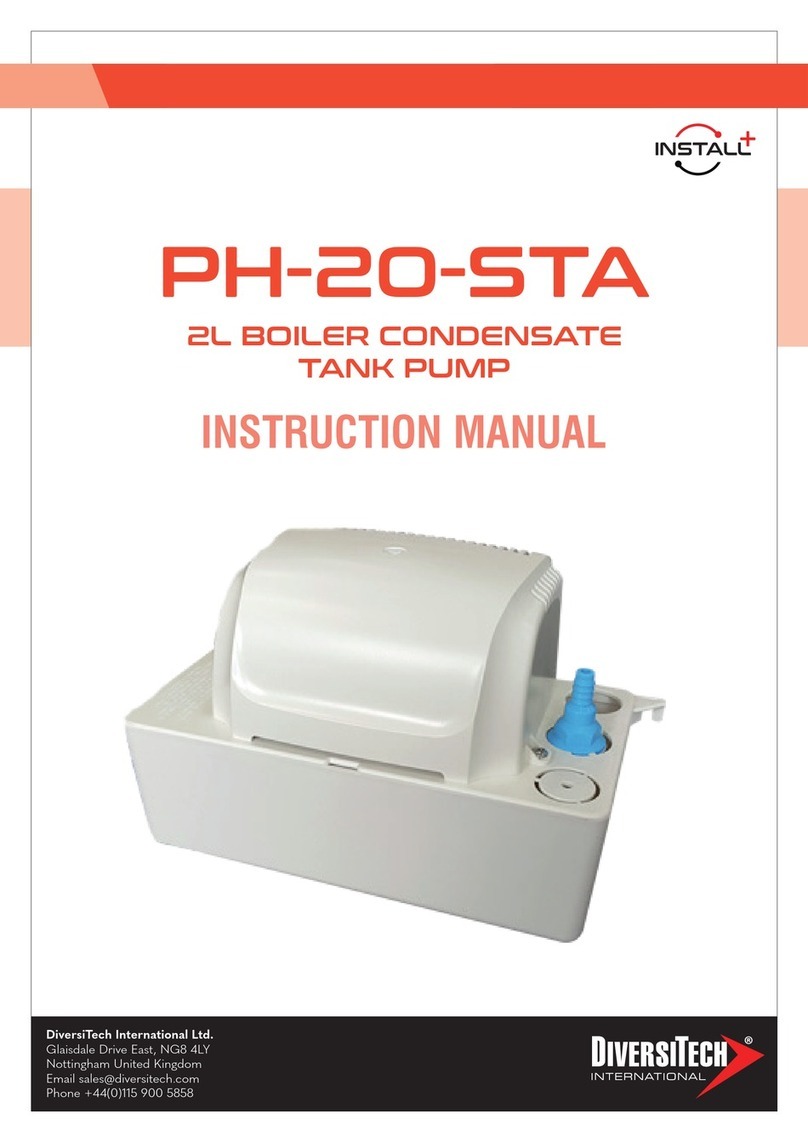
DIVERSITECH INSTALL+ PH-20-STA User manual

DIVERSITECH
DIVERSITECH Asurity ULTRACP-22 User manual

DIVERSITECH
DIVERSITECH ClearVue Mini User manual

DIVERSITECH
DIVERSITECH CP-22 User manual

DIVERSITECH
DIVERSITECH CP-NL20 Manual

DIVERSITECH
DIVERSITECH CP-22LP-P User manual

DIVERSITECH
DIVERSITECH Mini-Split CP-M230 User manual

DIVERSITECH
DIVERSITECH ASURITY PROCP-22S User manual
DIVERSITECH
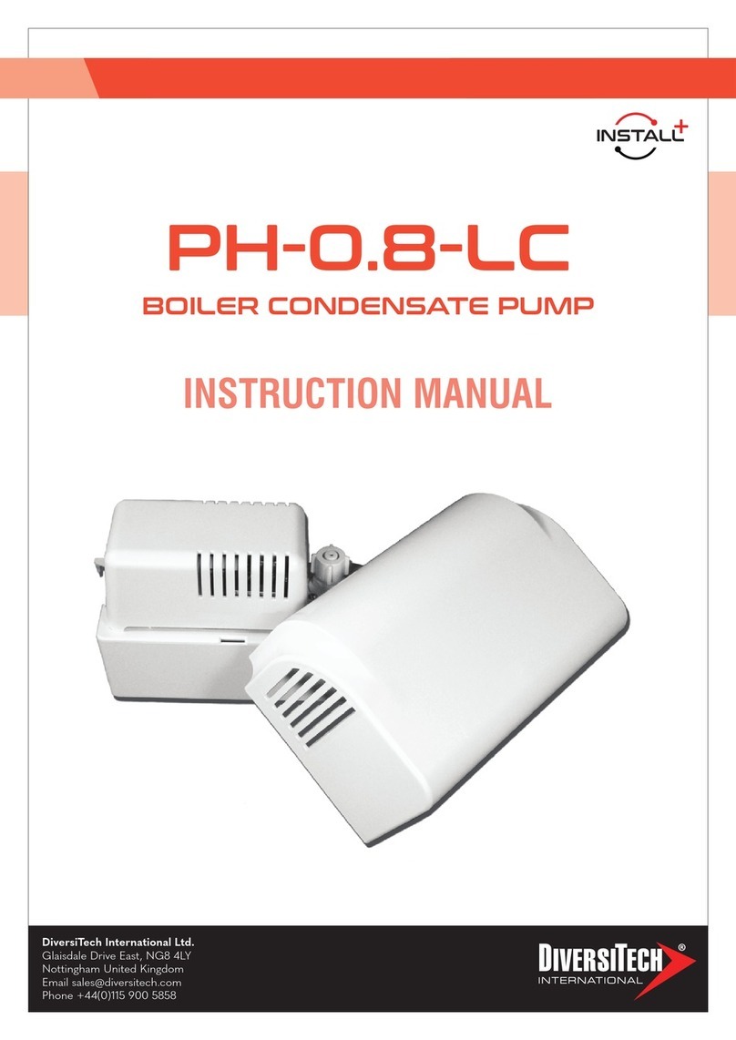
DIVERSITECH INSTALL+ PH-0.8-LC User manual

DIVERSITECH
DIVERSITECH CP-22 User manual
Popular Water Pump manuals by other brands

Watershed Innovations
Watershed Innovations HYDRAPUMP SMART FLEX Instructional manual

Graco
Graco Modu-Flo AL-5M instructions

Messner
Messner MultiSystem MPF 3000 operating instructions

Xylem
Xylem Bell & Gossett WEHT0311M Installation, operation and maintenance instructions

WilTec
WilTec 50739 Operation manual

Franklin Electric
Franklin Electric Little Giant 555702 HRK-360S instruction sheet

Ingersoll-Rand
Ingersoll-Rand PD02P Series Operator's manual

VS
VS ZJ Series Operating instruction

Flotec
Flotec FPZS50RP owner's manual

SKF
SKF Lincoln FlowMaster II User and maintenance instructions

Xylem
Xylem Lowara LSB Series Installation, operation and maintenance instructions

Water
Water Duro Pumps DCJ500 Operating & installation instructions

Action
Action P490 Operating instructions & parts manual

Flo King
Flo King Permacore Reusable Carbon Bag Disassembly. & Cleaning Instructions

ARO
ARO ARO PD15P-X Operator's manual

Pumptec
Pumptec 112V Series Operating instructions and parts manual

Virax
Virax 262070 user manual

Neptun
Neptun NPHW 5500 operating instructions
