idronaut OCEAN SEVEN 315 User manual


OCEAN SEVEN 315
ON-LINE MODULE
OPERATOR'S MANUAL
Copyright @ 1982 – 2015 Idronaut S.r.l. All rights reserved.
OCEAN SEVEN and Idronaut are registered trademarks of Idronaut S.r.l.
Other products and services mentioned in this document are identified by the trademarks or service marks of their respective companies
or organisations. No part of this publication, or any software included with it, may be reproduced, stored in a retrieval system, or
transmitted in any form or by any means, including photocopying, electronic, mechanical, recording or otherwise, without the prior
written permission of the copyright holder. Idronaut S.r.l. provides this document as is without warranty of any kind either expressed or
implied including, but not limited to, the implied warranties of merchantability and fitness for a particular purpose. Idronaut S.r.l. may
make changes of improvements in the equipment, software, firmware, or specifications described in this document at any time and
without notice. These changes may be incorporated in new releases of this document. This document may contain technical inaccuracies
or typographical errors. Idronaut S.r.l. waives responsibility of any labour, materials, or costs incurred by any person or party as a result
of using this document. Idronaut S.r.l. shall not be liable for any damages (including, but not limited to, consequential, indirect or
incidental, special damages, or loss of profits or data) even if they were foreseeable and Idronaut S.r.l. has been informed of their
potential occurrence arising out of or in connection with this document or its use.


IDRONAUT – Brugherio (MB) OCEAN SEVEN 315 On-Line Module 02-2015
OCEAN SEVEN 315 On-Line Module
IMPORTANT REMARKS
1) To obtain the best accuracy, the conductivity sensor and therefore the flow cell, must be fluxed by
clean seawater for at least 5 minutes.
CONDUCTIVITY MEASUREMENT
2) When the conductivity sensor is not in use, it is kept dry. Therefore, when the conductivity sensor is
placed in water, very small bubbles may remain attached to the platinum ring electrodes (seven). If
such a thing happens, the measured value of conductivity will be lower than the true one. To remove
these air bubbles, degrease the inside of the conductivity cell using cotton buds wetted with the
Conductivity Sensor Cleaning Solution or with liquid soap. Gently rotate the cotton bud against the
whole internal surface of the quartz cell. This will wet the platinum electrodes, thus reducing the
surface tension of the cell and considerably decreasing the risk of trapped air bubbles.
If the On-Line Module is not equipped with the Maintenance-Free Oxygen Sensor but with the oxygen sensor
provided with the black removable membrane cap, please carefully read section 1.9.4 and section 7.1.
OXYGEN MEASUREMENT
If the On-Line Module remains unused for periods longer than more than half a day, always place the white
plastic hydrating caps on both the pH and reference sensors. The caps must be respectively filled with the
pH7 Buffer Solution (or simply with clean water) and the Idronaut Reference Sensor Storage Solution (or
even with KCl saturated solution). Alternatively for a short time (i.e. half a day), immerse the module sensors
in clean water to prevent the pH and reference sensor dehydration.
pH MEASUREMENT
The IDRONAUT sensors are all pressure compensated and, in particular, the physical sensors (pressure,
temperature and conductivity) can last many years, if properly used. They are high-quality sensors, as they
are well known by oceanographers to measure salinity with great accuracy.
LIFETIME AND HOW TO REPLACE THE IDRONAUT SENSORS
If thoroughly maintained by their respective hydrating caps and solutions, the Idronaut pH and reference
sensors can last several years. The sensor replacement requires that the closure screws on the module cover be
unscrewed and the module electronics be removed from the metallic housing (this takes very few minutes).
All sensor heads have a standard 12 mm diameter and are provided with two o-rings (Parker 2-12) for sealing.
The pressure sensor is a high-quality transducer, which lasts many years if properly used. Its replacement is
not very easy and, moreover, it requires a Dead Weight Tester System to obtain the factory calibration
accuracy of 0.05% full scale.


IDRONAUT–Brugherio(MB) OCEANSEVEN315On‐LineModule 02‐2015
Copyrightstatement
CopyrightIDRONAUTS.r.l.
OCEANSEVENandIDRONAUTareregisteredtrademarksofIDRONAUTS.r.l.Allrightsreserved.
Thisdocumentmaynot,inwholeorinpart,becopied,photocopied,reproduced,translated,orreducedto
anyelectronicmediumormachine‐readableformwithoutpriorconsentinwritingfromIDRONAUTS.R.L.
Aboutthismanual
ThismanualservesasaguidetousetheOCEANSEVEN315On‐LineModule.
UseittounderstandthepurposeofeachoftheOn‐LineModulecomponentsandfunctions.
Ithelpsyoutounderstandthemodulebehaviour.
Itguidesyouthroughthemodulecapabilities.
Itservesyouasareferencewhensomeproblemsarisewhenusingthemodule.
Howtousethismanual
Thefollowingtopicsarecoveredbythismanual:
Section1 AdescriptionoftheOCEANSEVEN315On‐LineModule.
Section2 Installationandstart‐upoperations.
Section3 Dataacquisitionfunctionsanddataprocessingcapabilities.
Section4 Datastoragefunctions.
Section5 Sensorcalibrationfunctions.
Section6 Servicefunctions(configuration,diagnostics).
Section7 Modulemaintenance.
Section8 Troubleshooting
AppendixA DataProcessingFunctionPriming.
AppendixB Advancedconfigurationanddiagnostics.
AppendixC IDRONAUTITERM‐TerminalEmulationProgramme.
AppendixD Wireless“Bluetooth™”Interface.
AppendixE ConductivitywithIntegratedUV‐LEDAntifouling.
GettingStarted
TobetterunderstandtheOCEANSEVEN315On‐LineModulecapabilitiesandbehaviour,thereadershould
gothroughsections1and2.Theseallowtheusertogetintotouchwiththemoduleanditsaccessories.Itis
necessarytoalsoreadsections3and5andsection7beforestartingtooperatewiththemodule.The
remainingsectionsandappendicesaretobeconsultedonlywhenneeded.Moreover,incasethemoduleis
equippedwithexternalsensors/modules,deckunitsortheIDRONAUTportablereader,usefulinformation
arefoundindedicatedOperator’sManuals.
Notationalconventions
Throughoutthismanual,thefollowingconventionsareusedtodistinguishthevariouselementsofthetext:
[MODULECOMMANDS] Theyalwaysappearinuppercaseandbetween[]or<>brackets.
Modulemessages,userinputs Theyalwaysappearinitalics.
Definitionofterms
Throughoutthismanual,thefollowingtermsareused:
CastAsawholeofthedatasetcollectedinthesamewayinadetermined
samplingpoint.
DatasetAsawholeofconfiguredparametersexpressedinphysicalorchemical
unitsandacquisitiondate&time,collectedatprogrammedsampling
interval,(i.e.oncepersecond,onceperdepthincrement).

IDRONAUT – Brugherio (MB) OCEAN SEVEN 315 On-Line Module 02-2015
Raw data – ADC Counts As a whole set of data acquired by means of the ADC and the
conditioning circuits, from the configured sensors and is expressed
in numeric decimal or hexadecimal format.
Non-verbose mode This term refers to a module that has been configured to use a
communication protocol (computer oriented) to communicate with the
operator.
Verbose mode This term refers to a module that has been configured to use the MMI
functions to communicate with the operator.
ON condition This term refers to a fully operative module, waiting for commands
from the operator or running the requested command.
OFF condition This term refers to a module electronically switched off. In this state,
the module draws negligible amount of current from the battery.
MMI This term refers to the set of common rules, which the operator must
follow during the operation of module in verbose mode.
FSK Frequency Shift Keying.
The following documents are available in the “Literature & Manual” folder on the CD-ROM distributed with
the OCEAN SEVEN 315 On-Line Module.
IDRONAUT Documentation pertaining the OCEAN SEVEN 315 On-Line Module
OCEAN SEVEN Module Data Transmission Protocol Description.
Please visit our website download area for software updates and technical support:
Software updates and technical support
http://www.idronaut.it
The OCEAN SEVEN 315 On-Line Module is covered by a one-year limited warranty that extends to all parts
and labour and covers any malfunction that is due to poor workmanship or due to errors in the
manufacturing process. The warranty does not cover shortcomings that are due to the design, nor does it
cover any form of consequential damage because of errors in the measurements. In case of problem with your
OCEAN SEVEN 315 On-Line Module, first try to identify the problem by following the procedure outlined in
the troubleshooting section of this manual. Please contact your representative or IDRONAUT if the problem
is identified as a hardware problem or if you need additional help in identifying the problem.
Warranty
Please make
sure to contact IDRONAUT to obtain the relevant instructions before the OCEAN SEVEN 315 On-Line
module or any module is returned to IDRONAUT (see cleaning instructions)
For systems under warranty, IDRONAUT will attempt to ship replacement parts before the malfunctioning
part is returned. We encourage you to contact us immediately if a problem is detected and we will do our best
to minimize the downtime. Every effort has been made to ensure the accuracy of this manual. However,
IDRONAUT makes no warranties with respect to this documentation and disclaims any implied warranties
of merchantability and fitness for a particular purpose. IDRONAUT shall not be liable for any errors or for
incidental or consequential damages in connection with the furnishing, performance or use of this manual or
the examples herein. The information in this document is subject to change without notice.
.
Before the returned OCEAN SEVEN 315 On-Line Module can be serviced, equipment exposed to biological,
radioactive, or toxic materials must be cleaned and disinfected. Biological contamination is presumed for any
instrument, module, or other device that has been used with wastewater. Radioactive contamination is
presumed for any instrument, module or other device that has been used near any radioactive source. If an
OCEAN SEVEN 315 On-Line module, or other part is returned for service without following the cleaning
instructions, and if in our opinion it represents a potential biological or radioactive hazard, our service
personnel reserve the right to withhold service until appropriate cleaning, decontamination has been
completed.
Cleaning Instructions

IDRONAUT – Brugherio (MB) OCEAN SEVEN 315 On-Line Module 02-2015
When service is required, either at the user's facility or at IDRONAUT, the following steps must be taken to
insure the safety of our service personnel.
In a manner appropriate to each device, decontaminate all exposed surfaces, including any containers.
70% isopropyl alcohol or a solution of 1/4 cup bleach to 1-gallon tap water are suitable for most
disinfecting. Instruments used with wastewater may be disinfected with 5% Lysol if this is more
convenient to the user.
The user shall take normal precautions to prevent radioactive contamination and must use
appropriate decontamination procedures should exposure occur. If exposure has occurred, the
customer must certify that decontamination has been accomplished and that no radioactivity is
detectable by survey equipment.
Any product being returned to the IDRONAUT laboratory for service or repair should be packed
securely to prevent damage.
Cleaning must be completed on any product before returning it to IDRONAUT.
The recycling bin symbol on the product or on its packaging indicates that this product must not be disposed
of with your other waste. It is your responsibility to dispose of your waste equipment by handling it over to a
designated collection point for the recycling of waste electrical and electronic equipment. The separate
collection and recycling of your waste equipment at the time of disposal will help to conserve natural
resources and ensure that it is recycled in a manner that protects human health and the environment. For
more information about where you can drop off your waste equipment for recycling, please contact your local
city office, your waste disposal service.
Disposal of Waste Equipment by Users in the European Union


IDRONAUT – Brugherio (MB) OCEAN SEVEN 315 On-Line Module 02-2015
TABLE OF CONTENTS
1. Introduction 1
1.1. Module description 1
1.2. Sampling modes 1
1.3. Real-time communications 2
1.4. Management programmes 2
1.5. Standard sensor specifications 3
1.6. Optional sensor specifications 3
1.7. Electronic specifications 3
1.8. Physical characteristcs 4
1.9. The standard sensors 4
1.9.1. Pressure transducer 4
1.9.2. Temperature sensor 4
1.9.3. The conductivity sensor equipped with the “IDRONAUT seven-ring cell” 5
1.9.4. The oxygen sensor 5
1.9.4.1. The oxygen sensor (standard version) 5
1.9.4.2. The oxygen sensor maintenance-free version - 5 bar only 6
1.9.4.3. Oxygen measurement priming 7
1.9.4.4. Oxygen depletion / Stirring effect and/or Barometric pressure correction coefficients 7
1.9.5. pH and Reference sensors 7
1.9.6. The Redox sensor 8
1.10. Calculations 9
1.10.1.Oxygen 9
1.10.1.1.Calculation of solubility 9
1.10.1.2.Calculation of % saturation 9
1.10.1.3.Calculation of ppm 9
1.10.2.pH calculation and pH correction in relation to the sample temperature 9
1.10.3.Conductivity compensated at 20 °C 10
1.11. Module firmware overview 10
1.12. User interface 11
1.13. Menu & Submenus 11
1.14. Data entry functions 11
1.15. Menu & submenu structure 12
1.16. Menu header structure 12
1.17. Module Access Rights 13
1.18. Data transmission protocols 13
1.18.1.Point-to-point protocol 14
1.19. Field upgradeable firmware 14
1.20. Acquired data processing and post-processing 14
1.21. Low power consumption 14
1.22. Configuration 14
2. Installation and start-up 16
2.1. Shipping list 16
2.2. Laboratory RS232C cable 16
2.3. Installation 16
2.4. Start-up 16
2.4.1. RS232C/RS422 interface - Module power ON 17
2.4.2. Standard start-up messages 17
2.4.3. The Main Menu 17

IDRONAUT – Brugherio (MB) OCEAN SEVEN 315 On-Line Module 02-2015
2.5. Low power consumption 18
3. Data acquisition 19
3.1. The data acquisition menu 19
3.2. Acquired parameters 19
3.3. Common rule to set up the data acquisition cycle 19
3.4. Common rule to store acquired data 20
3.5. On-line acknowledgement 20
3.6. Unattended acknowledgement 20
3.7. Uploading data stored in the module memory 20
3.8. Unattended Acquisitions – Important Tips 21
3.9. Power consumption reduction 21
3.10. Warm-up 21
3.11. On/Off cycles 21
3.12. Shipping conditions 21
3.12.1.Sensors 21
3.13. Manual Data acquisition 22
3.14. Linear Data Acquisition 22
3.15. Timed data acquisition 22
3.15.1.Terminate a timed data acquisition 23
3.15.2.Automatic power OFF procedure 24
3.15.3.Accidental power ON cycle 24
3.15.4.Step-by-step procedure 25
3.16. Fast data acquisition 25
3.17. Programmed depth data acquisition 26
3.18. ConditionAL data acquisition 26
3.18.1.Terminate the Conditional data acquisition 27
3.18.2.Continuous data acquisition 28
3.18.3.Terminate the Continuous data acquisition 29
4. Data Storage 31
4.1. Memory organization 31
4.1.1. Cast area 31
4.1.2. Data records 31
4.1.3. Data Sets 32
4.2. Memory management 32
4.3. Show memory status 32
4.4. Show stored data 33
4.5. Delete Data 34
4.6. Initialize data memory 34
5. Sensor Calibration 35
5.1. Calibration storing layout 35
5.1.1. Parameter/Sensor logical codes 35
5.2. Sensor calibration functions 35
5.3. Calibrate the sensors 36
5.3.1. Selecting a wrong sensor 36
5.4. Customized calibration procedure 36
5.4.1. Pressure sensor 37
5.4.2. Temperature & Conductivity sensor calibration 37
5.4.3. Simple check of conductivity sensor calibration 38
5.4.4. Oxygen sensor calibration 38
5.4.5. pH sensor calibration 40
5.4.6. Redox sensor calibration 41
5.5. Other calibration procedures 42

IDRONAUT – Brugherio (MB) OCEAN SEVEN 315 On-Line Module 02-2015
5.5.1. SEAPOINT OEM Turbidity Meter 42
5.5.2. SEAPOINT OEM Fluorometer 44
5.6. Customize calibration data 44
6. Service, DiagnosticS & Configuration 45
6.1. The service menu 45
6.1.1. Raw data acquisition in ADC counts or mV 45
6.1.2. Firmware updating 46
6.1.2.1. Foreword 46
6.1.2.2. Firmware distribution package 46
6.1.2.3. How to carry out the firmware upgrading procedure 46
6.1.2.4. The upgrading procedure 47
6.1.2.5. Module identification 47
6.1.2.6. Download firmware 47
6.1.2.7. Updating the new firmware in the definitive FLASH memory 47
6.1.2.8. Firmware upgrading procedure failure 48
6.2. Module Diagnostic functions 48
6.2.1. The Diagnostics Menu 48
6.2.1.1. Test A/D Converter & mux 48
6.2.1.2. Service reading 49
6.2.1.3. Serial interface 49
6.2.1.4. Real-time clock 50
6.3. Module Configuration 50
6.3.1. Configuration memory layout 50
6.3.1.1. Default configuration values 50
6.3.1.2. Updating the configuration 50
6.3.2. Configuration menu 51
6.3.2.1. Data acquisition 51
6.3.2.2. Operating parameters 51
6.3.2.3. Acquired sensors 52
6.3.2.4. Available commands are: 53
6.3.2.5. List of the common sensors logical code 54
6.3.2.6. Programmed depth 54
6.3.2.7. Change date & time54
6.3.2.8. External systems 54
7. MODULE MAINTENANCE 56
7.1. Oxygen sensor 56
7.1.1. Green membrane 56
7.1.2. Refilling oxygen sensor cap with electrolyte 56
7.1.3. Membrane replacement (oxygen membrane cap) 57
7.1.4. Replacement of membrane can be done using the OXYGEN SENSOR MAINTENANCE KIT: 57
7.1.5. Oxygen sensor cleaning 58
7.1.6. Oxygen sensor check in the absence of oxygen 58
7.2. Reference sensor 59
7.3. pH SENSOR 59
7.3.1. To etch the sensor, perform the following: 59
7.3.2. Important remark on the pH measurement 60
7.4. Conductivity sensor 60
7.4.1. Important remarks on conductivity measurement 60
7.4.2. Conductivity sensor cleaning 60
7.4.3. Wetting the Conductivity sensor before laboratory calibration tests 60
7.5. Redox Sensor 61
7.6. Temperature Sensor 61

IDRONAUT – Brugherio (MB) OCEAN SEVEN 315 On-Line Module 02-2015
7.7. Pressure sensor 61
7.8. Data Memory and RTC battery 61
7.9. Routine maintenance schedule 61
8. Troubleshooting 62
Appendix “A” - Data Processing function priming 63
Appendix “B” – Advanced Configuration & Diagnostics 65
Appendix “C” – ITERM - Terminal Emulation program 66
Appendix “D” – Wireless Bluetooth Interface 71
Appendix “E” – Conductivity with Integrated UV-LED Antifouling 72
SECTION ONE – SYSTEM DESCRIPTION
IDRONAUT – Brugherio (MB) OCEAN SEVEN 315 On-Line Module 02-2015
1
1.
This section describes the main components of the OCEAN SEVEN 315 On-Line Module.
INTRODUCTION
1.1.
The OCEAN SEVEN 315 On-Line Module is based
on the well-known OCEAN SEVEN 316 probe (more
than 1000 units sold all over the world). The OCEAN
SEVEN 315 On-Line Module is equipped with the
well-known and proven IDRONAUT pressure
balanced full ocean depth, pump-free and long-term
stability sensors.
MODULE DESCRIPTION
Central to which, is the high
accuracy seven-platinum-ring conductivity sensor,
which can be cleaned in the field without the need for
re-calibration.
Acquired data is output through the standard RS232C interface at data rates up to 12Hz and up to 20
Hz using the IDRONAUT REDAS-5 software. Other interfaces like RS422 and Wireless Bluetooth can
be optionally installed.
For added flexibility, the OCEAN
SEVEN 315 On-Line Module can be operated in
either verbose or non-verbose mode, the latter being
especially convenient for system integrations on
buoys data loggers, ROVs and AUVs, or ferry-box
systems.
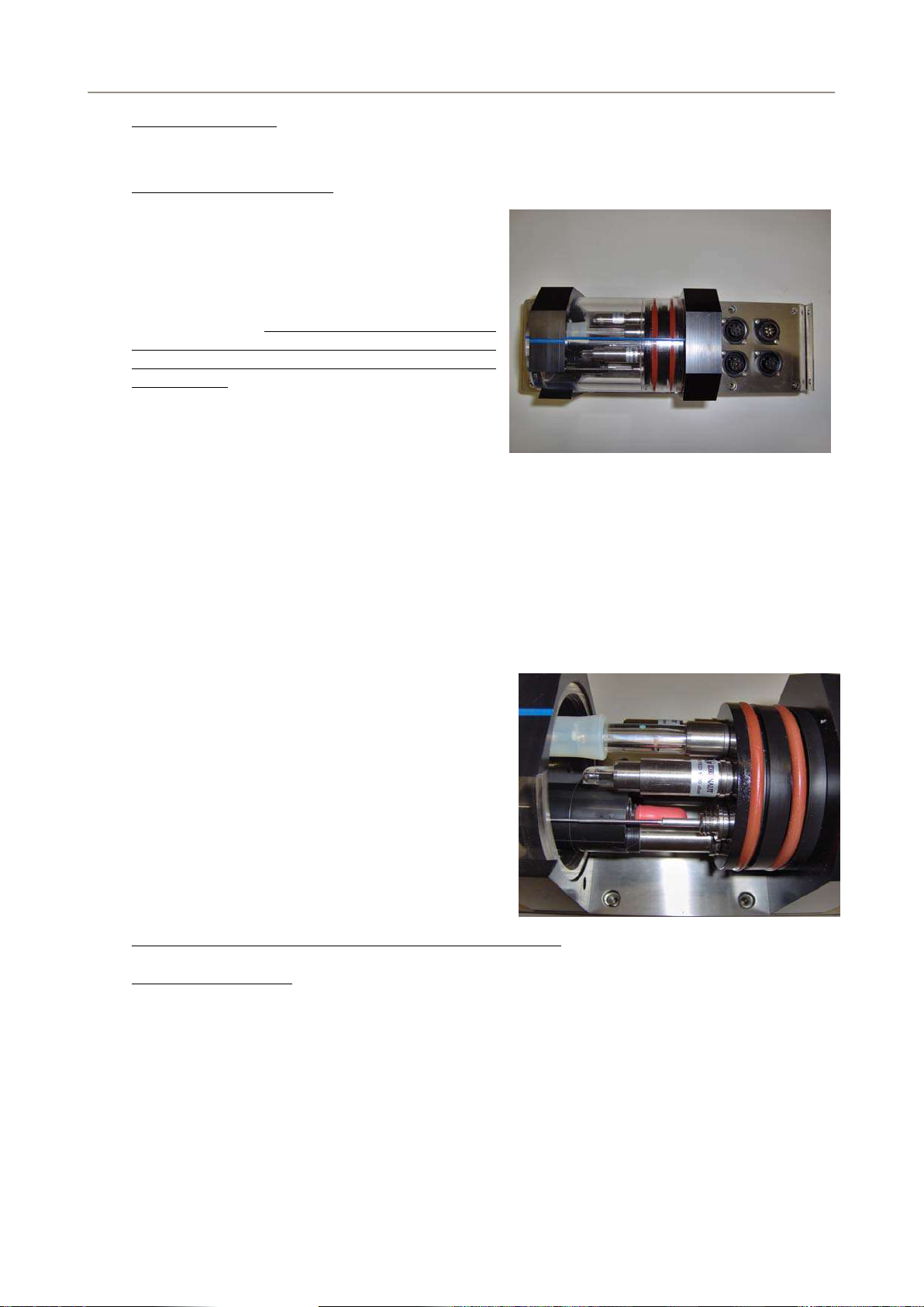
Four connectors located on the module cover provide connection for optional external optical sensors,
like Chlorophyll and/or Turbidity; Remote (Hull) temperature sensor; power supply and data
exchange with a suitable interfacing system.
The response time constant is 50 ms for the CTD sensors and 3 s for oxygen, pH and Redox. Software
compensation is provided for changes in the internal temperature of the module, in order to guarantee
both high performance and long-term stability. The electronic boards are fitted in a sealed housing
made of AISI316 Stainless Steel.
The OCEAN SEVEN 315 On-Line Module in its basic
configuration is equipped with three sensors: pressure
(to monitor the water flow), temperature and
conductivity. Other sensors can be optionally added,
like: dissolved oxygen, pH, redox.
Oxygen concentration in ppm, salinity, density, sound
velocity and other derived parameters are
automatically calculated.
The OCEAN SEVEN 315 On-Line Module interfaces:
IDRONAUT – Hull temperature sensor.
SEAPOINT - Fluorometer and Turbidity Meter.
Other equipment, sensors or modules can be interfaced upon request.
1.2.
The module is microprocessor-controlled and can be programmed to acquire and process data by
various different methods. Processed or raw data can be either transmitted in real time or stored inside
the instrument. Data acquisition methods includes:
SAMPLING MODES
Timed. The module collects a series of samples and then sleeps for the configured time interval
before waking up again and repeating the acquisitions. Time interval can be configured between
0.1s and 1 day. Power is conserved while the module is in sleep mode.
Conditional. Data acquisition is started and continues while the reading from a selected sensor is
above the threshold value. Whenever the acquisition cycle starts, a configurable sampling rate
0.1..12 Hz is used. Monitoring of the selected sensor threshold value can be configured to occur at
intervals between 0.1s and 1 day.

SECTION ONE – SYSTEM DESCRIPTION
IDRONAUT – Brugherio (MB) OCEAN SEVEN 315 On-Line Module 02-2015
2
Continuous. Data is sampled at configurable data rates starting when the operator switches on the
module. Sampling continues until the module is switched off. Multiple cycles can be obtained by
switching the module ON and OFF.
Real-time. Data is sent to the control system at data rates up to 12 Hz and up to 20 Hz using the
IDRONAUT REDAS-5 software.
1.3.
The OCEAN SEVEN 315 On-Line Module communicates with a
computer via a standard RS232C interface. Real-time data can be
acquired by means of the REDAS-5 Windows software. An
optional RS422 interface overcomes the limitation of the RS232C
cable maximum length (200 m) and allows the module to transmit
data through distances up to 1000 m. The communication speed is
user selectable among: 9600, 19200, and 38400. It is important to
mention that the OCEAN SEVEN 315 On-Line Module is insulated
from the communicating device, independently of the kind of
interface used: RS232C or RS422. Insulation guarantees that the sensors are not affected or disturbed by
ground loops or stray currents.
REAL-TIME COMMUNICATIONS
Connection type
Max cable length
Max. transfer rate
RS232C
200 m
38400 bps
RS422
1000 m
38400 bps
Wireless communication module: “Bluetooth™
The OCEAN SEVEN 315 On-Line Module can be optionally equipped with a Bluetooth™ module
which allows bidirectional full-duplex communications between the OCEAN SEVEN 315 On-Line
Module and a personal computer (Desktop, Laptop) or PDA devices equipped with a compatible
Bluetooth™ device. The wireless adapter is based on the well-known and diffused Bluetooth™
standard and is designed to provide an interface conforming to the Bluetooth™ v1.1 class 1. The
operating range of the adapter is specified in 100m although line-of-sight ranges of 300m can be
achieved. However, if a class-2 Bluetooth™ device is used to communicate with the OCEAN SEVEN
315 On-Line, then the range will be limited to 10-20m as foreseen by class-2 devices. The OCEAN
SEVEN 315 On-Line Bluetooth interface allows instant wireless connectivity to any device supporting a
compatible Bluetooth™ SPP protocol. The connection with the OCEAN SEVEN 315 On-Line Module,
among the Bluetooth™ devices registered on the network, is guaranteed by means of the unique PIN
code, which identifies each OCEAN SEVEN 315 On-Line Module. PIN value is predefined at factory
and cannot be modified by operator.
”
1.4.
IDRONAUT programmes, designed for any Windows operating system, allow the operator to
communicate with the OCEAN SEVEN 315 On-Line Module to perform attended or unattended data
acquisitions. The available programmes are:
MANAGEMENT PROGRAMMES
ITERM: IDRONAUT Terminal Emulation Programme and Module Management Programme to
easily communicate with the OCEAN SEVEN 315 On-Line Module. Diagnostics and
dedicated functions are included.
REDAS-5: Real-time data acquisition, processing and presentation programme, which allow the
numerical display and plotting of the standard sensors and the derived variables such as
salinity, sound speed, density, according to the UNESCO formulas and recommendations.

SECTION ONE – SYSTEM DESCRIPTION
IDRONAUT – Brugherio (MB) OCEAN SEVEN 315 On-Line Module 02-2015
3
1.5.
STANDARD SENSOR SPECIFICATIONS
Parameter Range Accuracy Resolution Time Constant
Pressure 0.. 1 bar 0.05 % F.S. 0.002% F.S. 50 ms
Temperature -3..+50 °C 0.003 °C 0.0002 °C 50 ms
Conductivity 0.. 70 mS/cm 0.003 mS/cm 0.0003 mS/cm 50 ms
Oxygen 0..50 ppm 0.1 ppm 0.01 ppm 3 s++
0..500 % sat. 1 % sat. 0.1 % sat. 3 s++
pH 0.. 14 pH 0.01 pH 0.001 pH 3 s
Redox -1000..+1000mV 1 mV 0.1 mV 3 s
2ndTemperature -3..+50 °C 0.01 °C 0.0002 °C 3 s
++ (from nitrogen to air)
The fundamental properties of seawater, like:
SALINITY, SOUND SPEED, WATER DENSITY, POTENTIAL TEMPERATURE, OXYGEN ppm are
obtained using the algorithms described in the UNESCO technical papers in marine science no. 44
"Algorithms for computation of fundamental properties of seawater".
1.6.
Among others, the OCEAN SEVEN 315 On-Line Module can be optionally equipped the optical
IDRONAUT OEM SEAPOINT Turbidity and Fluorometer sensors and, if used in fresh water, it can
also interface the I.S.E. Ion Selective Electrodes: ammonia, nitrate and chloride.
OPTIONAL SENSOR SPECIFICATIONS
Parameter Range Accuracy Resolution Time Constant
Ammonia(2) 0..100 mg/l-N 1mV
Nitrate(2) 0..100 mg/l-N 1mV
Chloride(2) 0.5..18000 mg/l-N 1mV
Turbidity Meter(1) 0.03.. 25 FTU/NTU 0.05 FTU/NTU 0.005 FTU/NTU 0.1 s
0.03.. 125 FTU/NTU 0.25 FTU/NTU 0.025 FTU/NTU 0.1 s
0.03.. 500 FTU/NTU 1 FTU/NTU 0.1 FTU/NTU 0.1 s
0.03.. 750 FTU/NTU** 5 FTU/NTU 0.5 FTU/NTU 0.1 s
0.03..4000 FTU/NTU*** 5 FTU/NTU 0.5 FTU/NTU 0.1 s
** output is non-linear above 750 FTU/NTU
*** output is non-linear above 1250 FTU/NTU
Please contact Idronaut to get the correct range.
Fluorometer(1) 0.02.. 5 ug/l 0.05 ug/l 0.002 ug/l 0.1 s
0.02.. 15 ug/l 0.1 ug/l 0.006 ug/l 0.1 s
0.02.. 50 ug/l 0.5 ug/l 0.02 ug/l 0.1 s
0.02..150 ug/l l 1 ug/l 0.06 ug/l 0.1 s
Note
2 – Only for fresh water application
: 1 - Specifications refer to the IDRONAUT OEM SEAPOINT Turbidity Meter and Fluorometer.
1.7.
Sampling frequency: 12 Hz raw data.
ELECTRONIC SPECIFICATIONS
Real-time data output rate: 12Hz; up to 20 Hz using REDAS-5 software.
Communication protocol: proprietary byte-oriented, binary and plain message protocol.
Operator interface: friendly menu-driven user interface.
Data memory 512-Mbyte non-volatile memory.
Battery power supply: 9 .. 18 V, 150 mA @ 12 V.

SECTION ONE – SYSTEM DESCRIPTION
IDRONAUT – Brugherio (MB) OCEAN SEVEN 315 On-Line Module 02-2015
4
1.8.
Dimensions WxLxH: 102x318x210 mm
PHYSICAL CHARACTERISTCS
Weight in air: 3.5 kg
Materials: black POM / AISI316L / Plexiglas
Connectors: 7-pole connector (Amphenol) for RS232C/RS422 outputs and power input. Wiring
details are attached to the Operator’s Manual.
1.9.
A detailed presentation of the OCEAN SEVEN sensors can be found in this section.
THE STANDARD SENSORS
1.9.1.
The pressure sensor is a high quality strain gauge, centrally mounted on the module base, capable of
generating a linear signal output, thus giving a resolution of 0.03% over the whole measuring range of 0 -
10000 dbar.
Pressure transducer
The pressure transducer, for this application, is required to monitor the water flow.
Type: strain gauge
Measurement range: 0..10000 dbar
Accuracy: 0.05%FS
Resolution 0.002%FS
Response time: 50 ms @1 m/s
Measurement bridge resistance: @ 25°C Ω 3500 ± 20%
Excitation current: 0.6 mA
Insulation: @ 50 VCC MΩ 100
Operating temperature: °C -30…100
Sensor body: AISI 316 L
Compensation: automatic compensation for temperature variations; not
compensated for the barometric pressure variations.
Life: unlimited.
Calibration frequency: monthly.
Maintenance: offset calibration in air.
1.9.2.
The temperature sensor consists of a platinum resistance
thermometer (type Pt 100 ohms at 0°C), fitted on a thin stainless
steel housing, able to withstand up to 700 bar. The sensor has a
very low response time (50 ms) and a high stability of reading with
ageing. The drift of reading (sensor plus associated electronics) is
less than 0.0003 °C per year.
Temperature sensor
Type: Pt100@0°C
Measurement range: -3..+50 °C
Accuracy: 0.003 °C
Resolution: 0.0002 °C
Response time: 50 ms @1 m/s
Maximum pressure: 700 bar
Sensor body: AISI 316L
Life: unlimited
Calibration frequency: yearly
Compensation: none.
Maintenance: none.

SECTION ONE – SYSTEM DESCRIPTION
IDRONAUT – Brugherio (MB) OCEAN SEVEN 315 On-Line Module 02-2015
5
1.9.3.
The conductivity sensor is a unique flow-through self-flushed cell with seven platinum ring electrodes.
The central ring is excited with alternate current flowing to both the outermost rings. The two adjacent
pairs of rings sense the relative drop in voltage due to the electrical conductivity of the measured
water.
The conductivity sensor equipped with the “IDRONAUT seven-ring cell”
The outermost pair of rings is grounded to shield the measuring cell from any outside electrical
interference.
The IDRONAUT conductivity sensor and its associated electronics are designed to work both with
plain and black platinised platinum electrodes These electrodes have the advantage that, they can be
used in both clean and dirty water without the fear of contamination. Should electrode contamination
occur, they can be easily cleaned (even with up to 30% hydrochloric acid) without affecting the module
performance or requiring re-calibration.
The cell is mounted in a special cylindrical plastic body, which guarantees thermic
insulation and is filled with silicone oil and provided with a rubber bellow to achieve pressure
compensation.
Because of its big internal diameter and short length, the cell does not need a pump, as it is easily
flushed during profiles.
The other conductivity flow cell sensors available on the market do not have the technology of the
“IDRONAUT seven-ring cell”.
The small, closely spaced temperature and conductivity free-flow sensors
eliminate the need for adding pumping.
Time constant of the
conductivity sensor is 50 ms, at 1 meter per second water flow.
Measurement cell: 7 platinum rings deposited inside
a quartz tube. Internal diameter
8mm, length 45mm.
Measurement range: 0..70 mS/cm
Accuracy: 0.003 mS/cm
Resolution: 0.0003 mS/cm
Response time: 50 ms @1 m/s
Max pressure: 700 bar
Sensor body: black plastic and titanium
Compensation: automatic compensation of the
pressure and thermal effect on the
cell geometry are performed by
the acquisition software.
Life: unlimited.
Calibration frequency: yearly.
Maintenance: cleaning using the IDRONAUT “Conductivity sensor cleaning
solution”.
1.9.4.
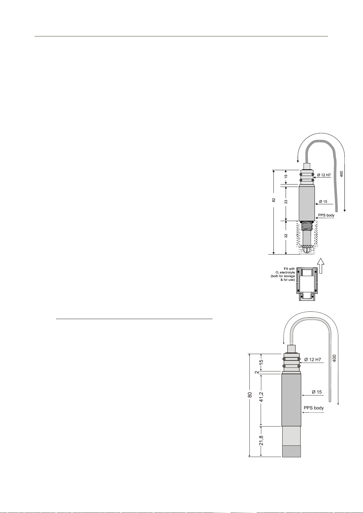
1.9.4.1.
The oxygen sensor
This section refers to the standard version (150 bar) only.
The oxygen sensor (standard version)
The oxygen sensor is of the polarographic type and consists of two half-cells, the anode and the cathode.
The anode is a silver tube inside the sensor, which encircles a glass body where a platinum wire,
forming the cathode, is sealed. The platinum wire (cathode) ends at the tip of the sensor where the
glass body is rounded. A special membrane cap with a gas-permeable replaceable membrane screw
onto the sensor. The inside of the cap is filled with a special electrolyte which allows the current
(measuring) to flow between the anode and the cathode. The membrane is shielded from accidental
bumps by a protective ring. The anode acts as a reference cell, providing a constant potential with
respect to the cathode. The cathode, where oxygen is consumed or reduced, is separated from the
sample to be analyzed by a thin layer of electrolyte and a special composite membrane. The electrolyte
permits the chemical reaction to occur whereas the membrane constitutes a barrier against ions and
other substances. By applying a polarizing voltage to the half-cells, the sensor develops a current
proportional to the concentration of oxygen in the sample in front of the cathode.
SECTION ONE – SYSTEM DESCRIPTION
IDRONAUT – Brugherio (MB) OCEAN SEVEN 315 On-Line Module 02-2015
6
Oxygen from the sample is drawn across the membrane, at the sensor tip, in the area of the cathode.
The applied polarization voltage is such that the sensor only responds to oxygen. The sensor is
insensitive to nitrogen, nitrous oxide, carbon dioxide and other gases. In order to avoid stray ground
current leaks, in case of membrane leaks, the anode is kept at ground potential while the cathode is
polarized at a fixed negative voltage. The oxygen sensor limits stirring effects on the measurement and
reads at least 97% of the true value, even with a stagnant aqueous sample. This is because the very
small cathode area and special cathode geometry, associated with a unique composite membrane,
minimize the consumption of the oxygen contained in the sample in contact with the membrane. The
function of this sensor depends on the reduction of oxygen at the cathode, as expressed by the formula:
O2+ 2 H2O + 4e->>> 4 OH-
The developed electrons represent the measuring current and are supplied by
the silver/silver chloride anode.
Type: polarographic with Pt/Ir cathode and
Ag(99.99%) anode
Measurement range: 0... 50 ppm 0… 500% sat.
Accuracy: 0.1 ppm 1 % sat.
Resolution: 0.01 ppm 0.1% sat.
Polarization voltage: 650 mV DC
Response time 3s (green membrane @20°C).
0.9 s (blue membrane @20°C).
Max Pressure: 150 bar.
Sensor body: POM plastic.
Compensation: automatic compensation of pressure
and thermal variations.
Life: 2 years if intensively used for
monitoring, up to 4 years if used
intermittently
Calibration frequency: weekly.
Maintenance: measuring membrane replacement,
electrolyte replacement.
1.9.4.2.
Type: polarographic with Pt/Ir
cathode and Ag(99.99%) anode
The oxygen sensor maintenance-free version - 5 bar only
Measurement range: 0... 50 ppm 0… 500% sat.
Accuracy: 0.1 ppm 1 % sat.
Resolution: 0.01 ppm 0.1% sat.
Polarization voltage: 650 mV DC
Response time: 30 s (membrane @ 20°C)
Max Pressure: 5 bar
Sensor body: black plastic (PPS)
Compensation: automatic compensation of
pressure and thermal
variations.
Life: 2 years if intensively used to
perform continuous monitoring,
up to 4 years if used
intermittently.
Calibration frequency: weekly.
Maintenance: maintenance free.
Table of contents
Other idronaut Control Unit manuals


