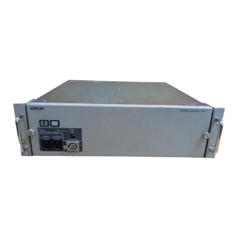
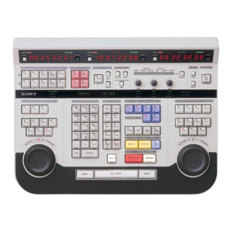
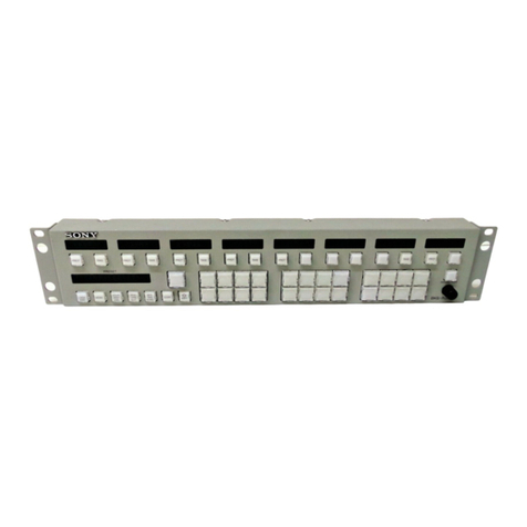
Sony RM-450 User manual

SAFETY-RELATED
COMPONENT
WARNING!!
COMPONENTS
IDENTIFIED
BY
MARK
A
OR
DOTTED
LINE
WITH
MARK
A
ON
THE
SCHEMATIC
DIAGRAMS
AND
IN
THE
PARTS
LIST
ARE
CRITICAL
TO
SAFE
OPERATION.
REPLACE
THESE
COMPONENTS
WITH
SONY
PARTS
WHOSE
PART
NUMBERS
APPEAR
AS
SHOWN
IN
THIS
MANUAL
OR
IN
SUPPLEMENTS
PUB-
LISHED
BY
SONY.
Se
aeae
ee
Model
UIC
Model
-RM-
450CE-
EK
Model
Teer
aya
EDITING
(
CONTROL
UNIT.
(G32
EDR)
WORSE
SMRT
SRM
rE
aA
Ha
RAT
If
>
T
(EBS
SUES
VET,
BS
«
PEREHHOK
OD,
DTBEORRSE
CHAFEE,
SO]
|
YY.
SERVICE
MANUAL
H-EAAAK/
HE
aan

RM-450
|
1.
SPECIFICATIONS
-rrccccerererrer
eerste
ereer
ree
1-1
(E)
BE
24
7-2
oe
>
Se
1-1
(J)
D.
FEATURES
ccecccsereecctrceesceseeersrretseeeeeens
2-1
(EB)
7
3
3:
Ma
2-1
(J)
:
3.
LOCATION
AND
FUNCTION
OF
:
3.
SRO
ZL
cerecceeree
eter
tteeeettteee
tees
3-1
G)
CONTROLS
cecrecceeerssteetesseesesesnetecesseenee
3-1
(E)
4.
FF
x
vy
RUFREMORR
4.
OPERATIONAL
CHECK
AND
1,
HERB
cesceesseeretsesceeeeseeeenseneseeeeeeees
4-1
()
FAULT
IDENTIFICATION
2,
H-ERBE
(CPUBRROF
=v
7
1,
Gereral
vrrrrrrscerrrssertereecerceecenerseeces
4-1
(E)
WARE
LAL
I
EG)
ceeeceeereeereeeeeteteees
4-1
(J)
2,
Service
Tools
(necessary
for
3.
DIVER
ey
7
OBR
veer
eee
eres
4-3
(J)
CPU
board
check)
crcccccssrtessseeeees
4-1
(E)
3.
Operation
Check
Procedure
+r:
4-3
(E)
5.
REMOVE
THE
RM-450
FROM
RACK
MOUNT
(lta
LUA)
dig
renataaecs
soaseeins
pensenmenaeanyatonsteero
reheat
rs
5-1
6.
SEMICONDUCTORS
(2238(K9}ER)
6—1,
Semiconductors
Pin
Assignments
6—2,
Semiconductor
Lead
Layouts
«rrrrrssssscesesssectseeeseneetetessseensecscessssesnreeesensacsensscecersnesseaeeereens
eres
seas
7.
DIAGRAMS
(447754)
TH,
Block
Diagram
crrrersscceessrsceressseesersseceeserssneseneessseesseeneneeeseseeeeneseeeeeee
sense
encase
eee
ee
eee
TEES
Tee
Cee
e
ey
=}
7-2,
Connections
CHEGERD)
crccereeeeeeereceeeerreeseteeeeeeseeseecesaceeesenenssescscessarnraarereseesssererecrssr
sees
eeeeeseneeeeee
ce ee
ee
7-83
7—B,
CPU-3
and
AC-1
boards
vorsrerceserssssrseeeeceesesresceeeersesensreeeeesseaeeesssenenneeseenesnsnsseseeeseeeense
seen
reese
eees
7-5
7-4,
DSP-1
Board
corterscereesccsseeessesseseeereesseeeeeees
errr
rer
rr
eterentrtrertereerererrrrrerterrertettrereier
irr
ccece
niin
7-11
8B.
EXPLODED
VIEWS
(4MIRBQ)
ccccceereeeeseersceseesecceeersrrerstssseeseesesessereeseersrncncaesennnsaresaccessseeesseeseeeeeeeeseeeee
eget
8-1
Q.
PARTS
LIST
CBBGLRE)
ccceeeceecceeeccesceescecessesseeesseesseeessereetsenessnerssessasssessscsserscesasessesneesneanaeeansessen
ages
aseeas
=
a

1.
SPECIFICATIONS
Automatic
controls
Manual
controls
Frame
modification
Digital
time
counter
Editing
accuracy
Connectors
PREVIEW,
AUTO
EDIT
/END
(Insert
/ASMBL),
RVW/JUMP,
LEARN
Player/Recorder
:
FF,
STILL,
REW,
PLAY,
search
dail
(%0
to
10
times
the
normal
playback
both
in
the
forward
and
reverse
directions)
Recorder
:
REC,
EDIT
IN
and
OUT
points,
possible
on
the
player
and/or
recorder
separately
in
the
manual
mode,
Time
code:
00:00:00:
00
to
23
:
59.:
59
:
29(24)
CTL/RTC
:
+9
:
59:
59
:
29(24)
to
—9:59:59:29(24)
or
00:00:00:
00
to
23:59:59:
29(24)
(selectable)
Time
code
mode:
£0
frame
during
synchronization
CTL
mode:
+1
farme
during
synchronization
AC
IN:
3pin
inlet
PLAYER//RECORDER
:
-9-pin/33-pin
connectors
CUE
OUT
BNC
connector,
Active
low
Low
level
0
to
0,5
V
High
level
3.5
to
5
V
REF,
VIDEO
IN:
BNC
connector,
75Q
unbalance
Composite,
video
signal
0,5
to
2
Vp-p
Composite
sync
input
signal
0.5
to
5
Vp-p
1-1
(E)
|
RM-450/RM-450CE
Power
requirements
U/C
AC
120
V
+10%,
50/60
Hz
+£10%
EK
AC220
V
—
240
V
+£10%,
50/60
Hz
+10%
Power
comsumption
11
W
Operating
temperature
0
to
40°
(82°F
to
104°F)
Dimensions
approx,
8390
X
93
X265
mm
(w/h/d)
(15%
x
8%
10%
inches)
Weight
.
approx.
3.1
kg
(6
Ib
113
oz)
Optional
accessories
33-pin
to
33-pin
remote
control
cable
RCC-5F
(5
m,
15
feet)
RCC-15FT
(15
m,
45
feet)
(for
extension)
9-pin
to
9-pin
remote
control
cable
RCC-5G
(5
m,
15
feet)
RCC-10G
(10
m,
30
feet)
RCC-30G
(30
m,
90
feet)
RMM-450
Rack
mount
metal
SU-450
Double
side
table

RM-450/RM-450CE
2.
FEATURES
“83-pin
and
@-pin
remote
control
connectors
These
two
types
of
remote
connectors
allow
the
unit
to
be
used
with
various
types
of
VTRs:
Betamax,
“BETACAM”
and
U-matic
VTRs,
and
even
a
1-inch
helical
scan
VTR
as
follows:
Type
of
a
VIR
Betamax
VTR
SLO-383/420
*
BVW-10*,
-40,
-75
series
.
BVU-800,
-900
series,
VO-5800
*
/5850
BVH-2000,
-3000
series
TLitime
code/ATC
(relative
time
code)
sélection
—
When
a
VTR
is
connected
through
the
9-pin
remote
contro!
connector,
you
can
select
a
CTL
signal,
time
code
or
RTC
(relative
time
code)
for
editing.
When
RTC
is
selected,
the
time
code
is
used
as
an
edit
reference
and
its
progress
is
counted
as
CTL
on
the
time
counter.
RTC
can
be
used
to
determine
how
far
the
desired
tape
point
is
from
the
IN
point
as
it
can
be
reset
in
the
same
manner
as
a
CTL.
ime
learning
capability
The
unit
can
detect
the
pinch
on
delay
time
of
the
connected
VTR
and
hold
this
data
for
a
week
even
after
the
power
is
turned
off.
Therefore,
the
operation
with
the
connected
VTRs
is
very
smooth
and
no
discontinuity
of
the
picture
is
produced
by
this
unit.
You
can
connect
not
only
the
VTRs
which
have
the
same
remote
connectors
but
also
VTRs
having
a
9-pin
remote
connector
and
those
having
a
33-pin
remote
connector
to
the
unit,
and
control
them
remotely.
In
the
assemble
mode,
the
video
signal
and
audio
signals
(A1
and
A2)
are
edited
together
at
the
same
time.
In
the
insert
edit
mode,
they
can
be
edited
separately.
The
unit
can
also
perform
the
split
edit.
Therefore,
you
can
set
the
audio
IN
point
independently
from
that
of
the
video
channel
and
vice
versa.
Materials
you
are
to
edit
can
be
previewed
and
those
that
you
have
edited
already
can
be
reviewed.
*
The
BVW-10
is
a
player,
and
other
VTRs
cannot
be
used
as
a
recorder
when
connected
to
this
unit.
You
can
easily
preset
various
data,
such
as
the
preroll
time
and
the
edit
timing,
needed
for
editing
on
the
front
panel.
Variable
speed
of
playback
functions
in
the
shuttle
mode
and
jog
mode
enable
you
to
locate
the.
edit
point
more
quickly.
‘Synchronize
The
REF.VIDEO
IN
connector
allows
the
unit
to
synchronize
with
the
connected
VTR.
Therefore,
the
unit
can
perform
absolutely
precise
editing.
When
the
VTR
which
has
the
dynamic
tracking
function
is
connected
to
this
unit
as
the
player
VTR,
this
unit
can
edit
the
picture
in
the
variable
speed.
AIR
SPSS
et
Te
SIERO
The
unit
indicates
the
error
by
displaying
the
error
number
on
the
time
counter
and
outputting
a
warning
sound.
You
can
understand
right
away
what
kind
of
error
has
occurred
and
what
you
should
do.
itable
The
unit
can
be
mounted
on
the
RMM-450
rack
mount
metal
which
is
designed
for
a
standard
19-inch
rack,
and
on
the
SU-500
series
system
console
by
using
the
SU-450
double
size
table.
2-1
(E)

RM-450/RM-450CE
3.
LOCATION
AND
FUNCTION
OF
PARTS
AND
CONTROLS
EO
IN
CUE-OUT
fr
RECORDER
Pe
a
aS
[1
|
REF.VIDEO
IN
connector
(BNC
type)
[4]
PLAYER
9-pin
connector
Supply
the
reference
signal
to
this
connector.
[5|PLAYER
33-pin
connector
[2]
RECORDER
9-pin
connector
Connect
to
the
9-pin
remote
connector
of
the
recorder
[6
|
CUE
OUT
connector
(BNC
type)
with
an
optional
remote
control
cable.
The
output
signal
from
this
connector
can
be
used
as
a-tally
signal.
[3|
RECORDER
33-pin
connecter
Connect
to
the
33-pin
remote
connector
of
the
[7]ac
IN
connector
;
recorder
with
an
optional
remote
control
cable.
Connect
to
the
AC
outlet
with
the
supplied
AC
power
cable.
3-1
(E)

RM-450/RM-450CE
[7]
(8)
(9) fol
fa
[12
POWER
switch
ON:
Set
to
this
position
to
turn
on
the
power.
OFF:
Set
to
this
position
to
turn
off
the
power.
[2]PLAYER
RESET
button
Press
this
button
to
reset
the
time
counter
and
the
entered
edit
points.
[3
|
PLAYER
button
group
The
function
of
these
buttons
is
the
same
as
those
on
the
player
VTR.
STDBY
(Standby)
button
EJECT
button
,
PLAY
button
STILL
button
REW
(Rewind)
button
FF
(Fast
Forward)
button
Time
counter
for
the
player
The
unit
counts
the
CTL
pulses
or
time
code
on
the
tape
of
the
player
and
displays
the
result
in
hours,
minutes,
seconds
and
frames.
Error
messages
are
also
displayed
here
when
errors
occur.
=
[5
|PLAYER
SERVO
indicator
This
indicator
lights
when
the
servo-mechanisms
of
the
player
are
not
locked
during
the
automatic
editing
and
preview
operation.
[6
|
PLAYER
IN
indicator
When
the
IN
point
of
the
player
VTR
is
entered,
this
indicator
lights.
PLAYER
OUT
indicator
When
the
OUT
point
of
the
player
is
entered,
this
indicator
lights.
[8]
AUDIO
SPLIT
button
Press
this
button
and
make
it
light
to
enter
the
audio
IN
point
during
the
split
editing.
ASMBL
(Assemble)
button
Press
this
button
for
assemble
editing.
INSERT
select
buttons
These
buttons
select
the
input
signal
during
insert
editing.
[11]
LAST
EDIT
button
This
button
recalls
the
previous
edit
points
on
the
time
counter.
3-2
(E)

RECORDER
IN
indicator
RECORDER
OUT
indicator
RECORDER
SERVO
indicator
[15]
Time
counter
for
the
recorder
RECORDER
RESET
button
[17]
TOTAL
button
and
lamp
The
lamp
blinks
when
the
button
is
pressed.
Then
press
the
RECORDER
RESET
button
[16]
to
reset
the
time
counter
of
the
recorder
to
00:00:00:00,
so
that
you
can
know
the
tape
running
time
from
after
that
point.
EDIT
button
For
manual
editing,
press
this
button
and
the
PLAY
button
[19]
simultaneously.
When
only
this
button
is
pressed,
the
picture
from
the
player
will
be
monitored
.
on
the
recorder
monitor.
RECORDER
button
group
The
function
of
these
buttons
is
the
same
as
those
on
the
recorder
VTR.
REC
(Record)
button
STDBY
(Standby)
button
EJECT
button
PLAY
button
STILL
button
REW
(Rewind)
button
FF
(Fast
Forward)
button
Search
dial
and
direction
lamps
for
the
recorder
This
dial
enables
you
to
locate
edit
points.
Push
in
to
change
from
the
shuttle
mode
to
the
jog
mode
and
push
it
again
to
return
to
the
shuttle
mode.
[21]
TRIM
+/—
button
Hold
this
button
down
while
pressing
the
IN
or
OUT
button
(22|
[28]
to
change
the
edit
points
frame
by
frame.
[22]
RECORDER
IN/OUT
buttons
Press
either
button
with
the
ENTRY
button
simultaneously
to
enter
the
IN
or
OUT
point
for
the
recorder.
|
RM-450/RM-450CE
[23]
ALL
STOP
button
Press
this
button
to
stop
the
tape
of
the
recorder
and
the
player.
RVW/JUMP
button
Press
this
button
to
review
the
edited
picture.
Only
the
recorder
operates
in
the
same
manner
as
during
editing.
Press
the
button
during
review
operation
to
locate
the
OUT
point
of
the
recorder.
[25]
AUTO
EDIT/END
button
Press
this
button
to
set
the
recorder
in
the
automatic
edit
mode.
When
you
press
this
button
during
editing,
the
unit
regards
the
tape
point
where
you
pressed
this
button
as
the
OUT
point,
and
finishes
editing.
PREVIEW
button
This
button
is
used
for
editing
rehearsal.
The
picture
you
are
to
edit
can
be
monitored
before
actual
editing.
27|
ENTRY
button
Press
this
button
with
the
IN
or
OUT
button
[22]
28]
to
enter
the
IN
or
OUT
point.
PLAYER
IN/OUT
buttons
GO
TO
button
Press
this
button
with
the
IN
or
OUT
button
[22]
[28]
to
locate
the
IN
or
OUT
point.
Search
dial
and
direction
lamps
for
the
player
STDBY
button
This
button
makes
the
VTR
shift
to
the
standby
off
mode
only.
EJECT
button
function
When
you
connect
the
VTRs
through
the
33-pin
connector,
the
eject
function
cannot
operate
with
the
EJECT
button.
3-3
(E}

RM-450/RM-450CE
LEARN
button
[5
|
SYNCHRO
(Synchronization)
selector
Press
the
button
to
detect
the
pinch
on
delay
time
of
Selects
the
way
to
synchronize
by
frame
pulse.
the
connected
VTRs
after
turning
on
the
unit.
ON/CF:
When
you
connect
the
VTR
having
a
9-pin
remote
connector
to
this
unit,
select
this
PLAYER
TC/RTC/CTL
selector
setting.
This
unit
counts
color
frames
to
Selects
the
time
data
displayed
in
hours,
minutes,
synchronize
the
player
and
the
recorder.
seconds
and
frames
on
the
respective
time
counter.
ON:
Synchronizes
the
recorder
and
the
player
CTL:
Time
period
of
tape
travel
by
counting
CTL
regardless
of
the
color
frame.
,
pulses.
OFF:
Does
not
control
synchronization.
RTC:
RTC
(Relative
Time
Code),
which
is
counted
as
a
time
code,
but
can
be
displayed
like
Dace
CTL.
¢
When
an
SLO-383
or
SLO-420
is
connected,
you
may
TC:
Time
code
not
be
able
to
synchronize
this
unit
and
it.
¢
Even
if
you
select
the
ON/CF
position
with
this
[3
|
PLAYER
9-pin/33-pin
selector
selector,
no
color
frame
can
be
counted
when
the
VTR
Selects
the
VTR
to
be
controlled:
the
VTR
connected
is
connected
through
the
33-pin
connector.
to
the
PLAYER
9-pin
connector
or
the
VTR
connected
to
the
PLAYER
33-pin
connector.
[6
]
RECORDER
9-pin/33-pin
selector
[4]
PREROLL
selector
RECORDER
TC/RTCICTL
selector
Selects
the
preroll
time:
3,
5,
7
(10)
seconds.
Preroll
time
selection
When
you
set
the
PREROLL
selector
[4]
to
7,
the
actual
preroil
time
depends
on
bit
7
of
the
left
DIP
switches
[8]
on
the
inside
panel.
3-4
(E)

RM-450/RM-450CE
SYSTEM
PRESET
DIP
switches
The
default
bits
setting
is
all
off
(0)
as
illustrated
below.
~
6
5
old
7
|
Maximum
preroll
time
is
set.
When
this
bit
is
set
to
ON,
the
preroll
time
is
set
to
410
seconds
even
though
the
PREROLL
selector
is
set
to
7
seconds.
ON:
10
sec.
OFF:
7
sec.
6
|
The
entry
of
the
edit
point
resets
the
time
counter
to
00:00:00:00
automatically.
This
bit
is
available
when
CTL
or
RTC
is
selected
with
the
TC/RTC/CTL
selector.
"ON:
The
time
counter
is
set
to
00:00:00:00
when
the
first
edit
point
is
entered.
Signal
standard
is
set.
ON:
PAL
or
SECAM
system
VTR
OFF:
NTSC
or
PAL-M
system
VTR
CTL
display
mode
is
selected.
This
bit
setting
is
available
only
when
you
set
the
RECORDER
and
PLAYER
TC/RTCI/CTL
selectors
to
CTL
or
RTC.
ON:
The
time
data
is
displayed
between
00:00:00:00
and
23:59:59:29.
:
OFF:
The
time data
is
displayed
between
—9:59:59:29
and
+9:59:59:29,
5
|
The
beep
sounds
when
any
key
is
pressed
or
when
the
tape
passes
the
edit
points
during
preview
or
automatic
editing.
ON:
The
beep
sounds.
The
operation
after
the
servo-mechanisms
cannot
be
locked
is
selected.
;
ON:
Even
though
the
unit
failed
to
servo-lock,
it
begins
editing.
OFF:
The
unit
does
not
begin
editing
until
the
4
|
The
SLO-420
videocassette
recorder
can
be
connected
servo-mechanisms
are
locked.
1
to
this
unit
or
not.
ON:
The
SLO-420
can
be
connected,
but
other
VTRs
cannot
be
connected.
OFF:
Another
VTR
is
connected.
The
operation
after
the
unit
fails
in
synchronizing
the
recorder
with
the
player
is
selected.
When
you
set
the
SYNCHRO
selector
to
ON
or
ONICF,
this
setting
is
available.
ON:
The
unit
will
synchronize
again
with
the
accuracy
of
no
frame
slipping.
When
it
finally
cannot,
the
unit
does
not
begin
editing.
OFF:
Even
if
the
recorder
is
not
synchronized
with
the
player,
the
editing
begins.
Synchronization
begins
depending
on
the
player's
or
recorder’s
operation.
ON:
Player
(The
time
base
corrector
must
be
installed
in
the
player.)
OFF:
Recorder
3
|
Where
to
output
the
CUE
signal
is
selected.
ON:
The
CUE
signal
is
output
after
the
IN
point.
OFF:
The
CUE
signal
is
output
before
the
IN
point.
2
|
CUE
OUT
start
position
is
set.
4
|
These
bits
determine
when
the
CUE
signal
is
output
0
|
after/before
the
IN
point:
0
to
7
seconds.
(0:
OFF
1:
ON)
000:
0
sec.
001:
1
sec.
010:
2
sec.
011:
3
sec.
400:
4
sec.
101:
5sec.
110:
6sec,
111:
7
sec.
*
These
bits
determine
the
edit
timing
during
editing
between
—1
and
—7
frames.
(0:
OFF
1:
ON)
000:
The
edit
timing
is
automatically
detected.
When
the
error
whose
number
is
11
occured,
select
another
one.
001:
—1
frames
010:
—2
frames
011:
-3
frames
100:
—4
frames
101:
—5
frames
110:
-6
frames
411:
—7
frames
3-5
(E)

RM-450/RM-450CE
4.
OPERATIONAL
CHECK
AND
FAULT
IDENTIFICATION
1.
General
No
electrical
adjustment
is
required
in
this
machine.
“Use
of
a
simple
checker
and
a
built-in
test
program
can
check
al!
operations.
A
test
program
activating
method
and
checking
items
are
described
below,
1-1.
Keyboard
check
Turn
On
the
POWER
switch
while
pressing
the
and
keys
at
the
same
time,
Checking
items
:
LED
ON/OFF
Non-locking
switch
operation
Locking
switch
operation
JOG/SHUTTLE
operation
of
Search
Dial
RS-232C
line
operation
of
KSW-1
-board
Backup
data
(LEARN
data)
verification
_
ROM
and
RAM
check
by
CPU
on
KSW-1
board
1-2.
Backup
function
check
in
keyboard
Turn
ON.
the
POWER
switch
while
pressing
the
and
keys
at
the
same
time,
Checking
items:
Backup
function
check
by
CPU
on
KSW-1
board
The
“Error”
is
displayed
when
the
POWER
switch
is
turned
ON
at
the
first
time
(or
when
the
backup
capacitor
C305
on
the
KSW-1
board
is
discharging).
Further
error
display
is
not
made
if
the
backup
function
is
normal.
The
capacitor
can
afford
to
provide
backup
for
at
least
seven
days.
1-3.
CPU
board
check
Turn
ON
the
POWER
switch
while
pressing
the
and
keys
at
the
same
time.
The
CPU
board
is
automatically
checked.
(Start
by
EJECT
key
on
the
RECORDER
side.)
If
a
fault
the
operation
is
stopped
immediately
and
the
error
code
is
displayed.
is
found,
For
this
purpose,
the
service
tools
are
required,
4-1
(E)
1-4.
Software
operation
check
and
REF.
VIDEO
circuit
check
Turn
ON
the
POWER
switch.
D219
(CHECK3
LED)
on
the
CPU
board
blinks
by
the
software,
In
addition,
D217
(CHECK1
LED)
blinks
when
a
signal
is
entered
into
the
REF,
VIDEO
IN
terminal,
1-5.
Address
bus
check
Power
ON
after
S201
OFF
Turn
OFF
the
8-bit
DIP
switch
S201
on
the
CPU
board
through
it
is
usually
set
to
ON
position.
The
CPU
then
executes
NOP
(00)
since
the
data
bus
on
the
CPU
board
is
isolated
from
devices
other
than
CPU
and
pulled
down
by
a
resistor.
At
this
time,
the
address
line
shows
simple
increments,
(However,
a
refreshed
address
is
assigned
to
A7
to
Al5,)
.
Observation
of
a
waveform
on
the
address
line
with
an
oscilloscope
makes
fault
identification
easier.
2.
Service
Tools
(necessary
for
CPU
board
check)
Ref,
Name
Part
Code
Q'ty
Usage
No.
J-l
9P
short
J-621-022-0A
2.
CPU-3
board
connector
operation
check
J-2
PLAYER,
J-621-020-OA
1
CPU-3
board
33P
short
operation
check
connector
J-3
RECORDER,,
J-621-021-0A
1
CPU-3
board
33P
short
operation
check
J-4
8-bit
DIP
1-570-623-11
1
CPU-3
board
switch
operation
check
J-5
VIDEO
signal
or
sync.
1
CPU-3
board
signal
generator
operation
check
Note:
J-1
to
J-4
are
contained
in
the
RM-450
service
kit
(J-621-019-0A).

|
RM-450/RM-450CE
Connection
A
COAXAL
CABLE
NTSC/PAL
COLOR
BAR
GENERATOR
ADJUSTMENT
POWER
;
SCTE
6P
CONNECTOR
oi
$202
cn208
=
©
INRA
BBD
RM-
450
UPPER
CONTROL
PANEL
CPU-3
BOARD
Connector
Circuit
Diagram
for
Service
Tools
J-621-022-0A
'
J-621-020-0A
J-621-021-0A
G1)
,
(J-2)
(3-3)
4-2
(E)

3M-450/RM-450CE
|
3.
Operation
Check
Procedure
(Detailed
description
for
1—1,
1-2,
and
1-3)
aI
CIT
7
88
‘88:68
‘BB
pg
eo
ge
22)
si
seg
(56:88:
Bre
|
HOURS
WINUTES
‘SECONDS
Lila
——
HOURS
MINUTES
[G6
88)
88:85)
FRAMES
Fig.
2
4-3
(E)

3-1.
Keyboard
check
1)
2)
3)
4)
5)
Turn
power
ON
while
pressing
@
|LEARN]
in
Fig.
1
and
@
[ASMBL]
in
Fig,
2
at
the
same
time,
Press
@
|EJECT}.
Again
press
@|EJECT],
and
“l1+-”
appears
on
7-segment
display
on
the
left
side.
Press
keys
in
the
order
of
©,
@,@:
@,
and
@.
Press
@
:
“92+”
appears
on
left
7-seg.
display
while
appears
on
right
7-seg.
display.
(1)
Place
all
indoor
switches
@
to
@
in
Fig,
1
in
upper
position,
and
press
@
[EJECT].
If
a
fault
is
found,
“Error”.
is
‘displayed,
In
this
case,
press
the
®
key,
then’
the
number
of
error
switch
is
displayed,
_
If
many
error
exist,
the
number
of
next
error
switch
is
displayed
whenever
press
the
@
|STDBY|
key.
For
switch
number,
refer
to
the
following.
5
6
7
ON/OF
5
ON’
3
OFF
78...13
14
15
t6...24
22
(2)
Place
the
above
switches
in
lower
position,
and
press
@
twice,
(3)
Place
@
@ @
and
@
switches
in
Fig,
1
in
center
position,
and
press
@
twice,
Press
@
[EJECT].
“33
++”
appears
on
the
left
display.
(1)
Set
both
search
dials
to
SHUTTLE.
Place
both
search
dials
in
the
center
position,
“Pl
on”
(2)
Check
that
left
search
dial
display
varies
as
shown
to
the
right
when
turning
left
search
dial
clockwise.
Check
that
display
as
shown
to
the
right
is
obtained
at
fully
clockwiswe
rotation.
The
same
change
must
appear
also
in
counter-
clockwise
rotation,
(8)
Check
that
turning
of
right
search
dial
provides
the
same
display
change
as
left
search
dial.
(4)
Set
both
search
dials
to
JOG,
(5)
When
both
search
dials
is
turned
Slowly
:
Quickly
:
4-4
(E)
|
RM-450/RM-450CE
All
LEDs
must
come
on,
All
LEDs
must
go
off,
01,
02---
7-segment
display.
No
error
display
allowed.
35,
OH
must
appear
on
right
“Pliu4150H”
must
appear
on
right
7-seg.
display.
No
error
display
allowed.
“P2.i.4144.,0H”
must
appear
on
the
right
display,
“P38.
u404.50H”
must
appear
on
the
right
display.
The
right
display
must
indicate
“0000
0000”,
(Left
half
for
left
search
dial,
and
right
half
for
right
search
dial.)
0000
~
0001
~
0010
—
0011
—
0100
~
0101
0110
>
0111
1000
The
right
display
must
indicate
“00
00”,
(Left
half
for
left
search
dial
and
right
half
for
right
search
dial.)
The
first
digit
of
each
display
must
vary.
The
second
digit
of
each
display
must
vary.

{M-450/RM-450CE
6)
Press
@
[EJECT].
‘44-"
and
“232c”
appear
on
the
left
and
right
displays
respectively.
Again
press
the
@
key,
“Error”
must
appear
on
the
right
display.
(At
this
time
,
if
pins
@,@
of
CN207
on
CPU-3
board
are
disconnected,
then
shorted
instead,
“OH”
is
displayed.)
7)
Press
the
@
twice.
“66-+*"
appears
on
the
left
display.
“OH”
must
appear
on
the
right
display.
3-2.
Backup
function
check
in
keyboard
1)
Turn
OFF
the
POWER.
switch,
:
2)
Turn
ON
the
POWER
switch
while
pressing
@
|LEARN
and
©
at
the
same
time,
3)
Turn
OFF
the
POWER
switch,
4)
About
5
minutes
past,
turn
ON
the
POWER
switch
while
Neeeeeeee
”
and
“XXXKXXXXX”
must
appear
on
pressing
@
[LEARN]
and
©
keys
at
the
same
time,
the
left
and
right
displays
respectively.
3-3.
Bottom
case
check
(available
only
when
7-segment
display
is
active)
3-3-1,
Preparation
1)
Remove
the
keyboard,
.
Insert
the
8-bit
DIP
switch
(J-4,
1-570-623-11)
into
the
IC
socket
labelled
S202
(CHECKER)
on
the
CPU
board,
(Remove
this
switch
after
checking.)
(3)
Turn
ON
7
bits
on
the
left
side
and
turn
OFF
1
bit
on
the
right
side,
(4)
Mount
the
connectors
J-1,
J-2,
and
J-3
of
the
service
tools.
(5)
Connect
the
VIDEO
signal
to
the
REF.
VIDEO
IN
terminal,
(6)
Install
the
keyboard,
(
(2
8-3-2,
Procedure
(1)
Turn
ON
the
POWER
switch
while
pressing
“450”
and
“XX-X”
must
appear
on
the
left
@®
in
Fig.
1
and
@
in
Fig,
2
at
the
and
right
displays
respectively.
:
same
time,
Ql,
02,
++
18
must
appear
sequentially
on
the
(2)
Press
@
in
Fig.
2,
left
display,
then,
“--------
"and
“--------
i
appear
on
both
displays
finally,
followed
by
beeps,
:
(8)
Remove
the
DIP
switch
from
$202.
3-3-8,
Fault
identification
If
a
fault
is
found,
operation
is
stopped
immediately,
Display
example
for
faulty
place:
Left
display:
07
Right
display:
01
01
4
J J
STEP
Error
No,
Error
code
in
STEP
To
confirm
whether
additional
error
codes
are
present
in
the
same
step,
press
@
|STDBY|
key
in
Flg,
2,
Unchanged
error
No.
in
the
step
indicates
there
is
no
additional
error
in
the
step.
To
proceed
to
the
next
step,
press
@
[EJECT]
key
in
Fig.2,
For
the
meaning
of
error
code,
see
the
Error
Code
List,
4-5
(E)

RIM-450/RM-450CE
RM-450
Self
Check
Program
Error
Code
List
Meaning
ROM
Check
Sum
Error
:
02
01
RAM
Read/Write
Error
03
00
CTCI1
chl
Initialize
NG
01
CTC1
chl
Count
Down
NG
02
CTC1
chl
Timer
INT
Error
04
00
CTC2
ch3
Initialize
NG
01
CTC2
ch3
Count
Down
NG
02
CTC2
ch3
Timer
INT
Error
05
20
CTC2
chO
Initialize
NG
21
CTC2
chil
Initialize
NG
06
31
CTC3
chi
Initialize
NG
33.
|
CTC3
ch3
Initialize
NG
:
EXT
SYNC
Check
07
00
CTC1
ch0
Initialize
NG
Ol
REF,
VIDEO
IN
NG
02
F2,/F1
(Framing)
Pulse
Width
too
Wide
03
F2,/F1
(Framing)
Pulse
Width
too
Narrow
SIO,
R-9P/P-9P
REMOTE
Check
;
08
Ol
chA
(Recorder)
Tx
NG
02
chA
(Recorder)
Rx
NG
(R-TxD~R-RxD
Line
NG)
03
chA
(Recorder)
Data
NG
(R-TxD~R-RxD
Data
not
equa!)
04
chB
(Player)
Tx
NG
05
chB
(Player)
Rx
NG
(P—TxD->P—RxD
Line
NG)
06
chB
(Player)
Data
NG
(P-TxD-P-—RxD
Data
not
equal)
INT
Error
:
ROM
:
IC219
CTC]
:
1C225
SIO
:
1C212
RAM
:
1C215
CTC2
:
1C224
CTC3
:
1C221
33P
S/C,
R-83P
REMOTE
Check
R
(Recorder)
09
90
RESET1
(PW
Detect)
NG
98
SYSTEM,
CLOCK
or
STROBE
NG
99
SERIAL
IN/OUT
NG
09
09
EDIT
SAFETY
or
EDIT
LAMP
stuck
at
sf
By
19
REC
KEY
or
REC
LAMP
stuck
at
“L”
29
EDIT
KEY
or
PAUSE
LAMP
stuck
at
“L”
39
CUT
OUT
or
TAPE
STOP
or
STOP
KEY
stuck
at
bys
59
FWD
LAMP
or
FWD
KEY
or
PAUSE
KEY
stuck
at
“L”
69
FF
LAMP
or
FF
KEY
or
FWD/REV
stuck
at
“Ts
79
REW
LAMP
or
REW
KEY
or
FUNC
ON
stuck
at
“UL”
09
01
EDIT
SAFETY
or
EDIT
LAMP
short
w/
SERIAL
IN/OUT
02
EDIT
SAFETY
or
EDIT
LAMP
stuck
at
“He
03
EDIT
SAFETY
or
EDIT
LAMP
short
w/
REC
LAMP
or
REC
KEY
04
EDIT
SAFETY
or
EDIT
LAMP
short
w/
PAUSE
LAMP
or
EDIT
KEY
05
EDIT
SAFETY
or
EDIT
LAMP
short
w/
FF
KEY
&
LAMP
or.
FWD/REV
EDIT
SAFETY
or
EDIT
LAMP
short
w/
FWD
KEY
&
LAMP
or
PAUSE
KEY
EDIT
SAFETY
or
EDIT
LAMP
short
w/
REW
KEY
&
LAMP
or
FUNC
ON
EDIT
SAFETY
or
EDIT
LAMP
short
w/
TAPE
STOP
or
CUT
OUT
or
STOP
KEY
09
11
REC
KEY
or
REC
LAMP
short
w/
SERIAL
IN/OUT
12
REC
KEY
or
REC
LAMP
stuck
at
“H”
13
REC
KEY
or
REC
LAMP
short
w
PAUSE
LAMP
or
EDIT
KEY
|
14
REC
KEY
or
REC
LAMP
short
w/
FF
KEY
&
LAMP
or
FWD/REV
15
REC
KEY
or
REC
LAMP
short
w/
FWD
KEY
&
LAMP
or
PAUSE
KEY
16
REC
KEY
or
REC
LAMP
short
w/
REW
KEY
&
LAMP
or
FUNC
ON
17
REC
KEY
or
REC
LAMP
short
w/
TAPE
STOP
or
CUT
OUT
or
STOP
KEY
4-6
(E)

{M-450/RM-450CE
Meaning
PAUSE
LAMP
short
w/
SERIAL
IN/OUT
EDIT
KEY
or
PAUSE
LAMP
stuck
at
“H”
EDIT
KEY
or
PAUSE
LAMP
short
w/
FF
KEY
&
LAMP
or
FWD/REV
EDIT
KEY
or
PAUSE
LAMP
short
w/
FWDFWD
KEY
&
LAMP
or
FWD/REV
EDIT
KEY
or
PAUSE
LAMP
short
w/
REW
KEY
&
LAMP
or
PAUSE
KEY
EDIT
KEY
or
PAUSE
LAMP
short
w/
TAPE
STOP
or
CUT
OUT
or
STOP
KEY
R
38P
S/C:
1C204
CUT
OUT
or
TAPE
STOP
or
STOP
KEY
short
w/
SERIAL
IN/OUT
CUT
OUT
or
TAPE
STOP
stuck
at
“
H”
CUT
OUT
or
TAPE
STOP
or
STOP
KEY
short
w/
FF
KEY
&
LAMP
or
FWD/REV
CUT
OUT
or
TAPE
STOP
or
STOP
KEY
short
w/%
FWD
KEY
&
LAMP
or
PAUSE
KEY
CUT
OUT
or
TAPE
STOP
or
STOP
KEY
short
w/
REW
KEY
&
LAMP
or
FUNC
ON
STOP
KEY
or
TAPE
STOP
stuck
at
“H”
10
20
CTC2
chO
TRG
INT
Error
or
STOP
KEY
NG
30
CTC3
chl
TRG
INT
Error
or
SEARCH
SPEED
NG
or
CTL
IN/OUT
NG
PAUSE
KEY
or
FWD
KEY
&
LAMP
short
w/
SERIAL
IN/OUT
PAUSE
KEY
or
FWD
LAMP
stuck
at
“H”
PAUSE
KEY
or
FWD
KEY
&
LAMP
short
w/
FF
KEY
&
LAMP
or
FWD/REV
PAUSE
KEY
or
FWD
KEY
&
LAMP
short
w/
REW
KEY
&
LAMP
or
FUNC
ON
FWD/REV
or
FF
KEY
&
LAMP
short
w/
SERIAL
IN/OUT
FWD/REV
or
FF
LAMP
stuck
at.
“H”.
FWD/REV
or
FF
KEY
&
LAMP
short
w/
SERIAL
IN/OUT
REW
KEY
&
LAMP
or
FUNC
ON
short
w/
SERIAL
IN/OUT
REW
KEY
or
REW
LAMP
stuck
at
“H”
REW
KEY
short
w/
REW
LAMP
or
REW
LAMP’s
CR
(470p/1M)
NG
FF
KEY
or
FF
LAMP
stuck
at
“H”
FF
KEY
short
w/
FF
LAMP
or
FF
LAMP’s
CR
(470p/1M)
NG
FWD
KEY
or
FWD
LAMP
stuck
at
“H”
FWD
KEY
short
w,/
FWD
LAMP
or
FWD
LAMP’s
CR
(470p//1M)
NG
FUNC
ON
or
REW
LAMP
stuck
at
“H”
P
(Player)
83P
SC,
P-883P
REMOTE
Check
RESET1
(PW
Detect)
NG
SYSTEM
CLOCK
or
STROBE
NG
SERIAL
I/O
NG
TAPE
STOP
or
STOP
KEY
or
REW
KEY
stuck
at
“L”
REW
LAMP
or
STOP
KEY
or
REW
KEY
stuck
at
FWD
LAMP
or
FWD
KEY
or
PAUSE
KEY
stuck
at
FF
LAMP
or
FF
KEY
or
FWD/REV
stuck
at
“L”
FUNC
ON
or
PAUSE
LAMP
stuck
at
“L”
“rv?
“[?
STOP
KEY
or
TAPE
STOP
or
REW
KEY
&
LAMP
short
w/
SERIAL
IN/OUT
STOP
KEY
or
TAPE
STOP
stuck
at
“H”
STOP
KEY
or
REW
LAMP
stuck
at
“H”
STOP
KEY
or
TAPE
STOP
or
REW
KEY.
&
LAMP
short
w/
FWD
KEY
&
LAMP
; :
or
PAUSE
KEY
STOP
KEY
or
TAPE
STOP
or
REW
KEY
&
LAMP
short
w/
FF
KEY
&
LAMP
:
or
PAUSE
KEY
STOP
KEY
or
TAPE
STOP
or
REW
KEY
&
LAMP
short
w/
PAUSE
LAMP
or
FUNC
ON
PAUSE
KEY
or
FWD
KEY
&
LAMP
short
w/
SERIAL
IN/OUT
PAUSE
KEY
or
FWD
LAMP
stuck
at
“H”
PAUSE
KEY
or
FWD
KEY
&
LAMP
short
w/
FF
KEY
&
LAMP
or
FWD/REV
PAUSE
KEY
or
FWD
KEY
&
LAMP
short
w7
PAUSE
LAMP
or
FUNC
ON
FWD/REV
or
FF
KEY
&
LAMP
short
w/“
SERIAL
IN/OUT.
FWD/REV
or
FF
LAMP
stuck
at
“H”
.
FWD/REV
or
FF
KEY
&
LAMP
short
w/
PAUSE
LAMP
or
FUNC
ON
4-7
(E)

RM-450/RM-450CE
Step
Code
0
REW
KEY
or
REW
LAMP
stuck
at
“H”
REW
KEY
short
w”
REW
LAMP
or
REW
LAMP’s
CR
(470p/1M)
NG
FF
KEY
or
FF
LAMP
stuck
at
“H”
FF
KEY
short
w/
FF
LAMP
or
FF
LAMP’s
CR
(470p/1M)
NG
FWD
KEY
or
FWD
LAMP
stuck
at
“H”
FWD
KEY
short
w/
FWD
LAMP
or
FF
LAMP’s
CR
(470p/1M)
NG
FUNC
ON
or
PAUSE
LAMP
short
w/
SERIAL
IN/OUT
FUNC
ON
or
PAUSE
LAMP
stuck
at
“H”
CTC2
chl
TRG
INT
Error
CTC3
ch3
TRG
INT
Error
or
SEARCH
SPEED
NG
or
CTL
IN/OUT
NG
R
33P
S/C
:
1C203
:
73
EF
~y
bw
oO
oo wh
0
F
0
E
ee
|
oo
Oorjl~on
10
wn
ee
Daisy
Chain
(Display
according
to
Priority)
11
00
SIO
INT
PRIORITY
NG
Ol
CTCl
INT
PRIORITY
NG
02
CTC2
INT
PRIORITY
NG
03
CTC3
INT
PRIORITY
NG
*
SIO
>CTC1>CTC2>CTC3
CUE
OUT
(Using
P
33P
S/C
for
This
Check)
12
01
CUE
OUT
and
SLOW
LAMP
stuck
at
“H”
CUE
OUT
and
SLOW
LAMP
stuck
at
“L”
ERROR/KEY
BEEP
(Check
BEEP
ON
or
Not)
;
4-8
(E)

{M-450_
|

1.
#RBRILER
Bigay
bu—wv
#Fioyvbha—w
7V—
LMBIE
PALADVYDI
iA
ARDS
REVIEW,
AUTO
EDIT/END
(4
¥
s—
hk,
TRY
TV),
RVW/JUMP,
LEARN
Fv—-véva—-y:
FF,
STILL,
REW,
PLAY,
#}-F
94
VI)
CEs
Fila]
1730
Aes
~
10
ak)
Vv2a—¥O4
:
REC,
EDIT
INK,
OUTH,
FTLU-¥,
VA-FH
BRE
FA
LAI—F:
00:00:00:
00~
23
:
59
:
59:
29
+9:59:59:29~
—9:59:59:29#¢k
{£00
:
00:
00
:
0OO~
23
59:59:29
(HR
TYRE)
94
L3—
PRM
:
gute
+O
7LV—L
CTL
St
:
FABRE
41
DV—-4L
ACAHAATY
BEY)
9EYaIRYY
(FU-¥,
VA-Y¥)
CUE
OUTIAZYX
(BNC!)
CTL/RTC
:
FIFT4T7T
LOW
LOW
UAW:
0~0.5V
HIGH
VADs:
3.5~5V
REF,
VIDEO
IN2%7%
(BNC#)
758Q
AEB
ayy
HEF
ALES
:
0.5~2Vp-p
ayy
by
vy
7s
:
0.5~5Vp-p
1-1
(J)
i
BREA
Dei
Be
RANE
TE
B
HE
BOT
7
er)
Rivi-450
AC100V+10%,
50/60Hz+
10%
11W
0°C~40°C
390
X93X
265mm
(w/h/d)
38.ikg
VEavy—-TW
(38%Y
/33E
VY)
RCC-5F
(5m)
RCC-15FT
(15m
XERFA)
YEavy—-TW
Q9EV/IEY)
RCC-5G
(5m)
RCC-10G
(10m).
RCC-30G
(30m)
Sy72IYbAHW
RMM-450
YADNMPARF-TN
SU-450

RM-450
2),
aE
“B3EYBKUI
sepomieaepiniaey
OBEOUIROS
BBL.
SEVIRCHIL<
MAGA
rorie
-CETEES
o
WIRVIR
nR-¥
R—SALs
|
sio-383,
420
-
BVW-10,40,
75U—X
BVU-800,
900
—X.
VO-5800,
5850
BVH-2000,
30007U—X
Uae.
14
yF
(BVW-10(¢
B+
SRBC
SLO-420¢VO-5800
IC
lt
RE
BREDBOKRSD,
HEORISFL—P-CUCTHEUCE
Wo)
FAS
SIROS—-OBMA,
FL-V-,
LD
I-F—AllN
IBRORET.
THICKO,
QE
YIAIRIY—OVTIRES3
PYIRIF—OVIREMPADE
T
Oise
6
FW
AETS
o
CTL.
94
LA—-K,
RI
COBRA
AE
QLYIRIS—OVIREBMT
SL,
VI
LNDVI—-R®
RELTCTILADY
AK,
91
LI—KROIEAMERTC
(Relative
Time
Code)
@2RTSCCHCEET.
RICIt,
97
AAI—KOWN,
MODECTLADY
MBCA
MICRRTS,
MUS
1IOV1LADYS—-RRCS.
S94
bI-h@RHOBBEGMRE.
SOBRICTISTZ
ACHSLDICMOELES
;
RELABRBE
PREY
TS
CISESA
EAT
4
A(2FPUAIL)
€A
PRICMMSL.
TON
MR
CSENENSBBC,
KES
WHADEUTMRLET.
TUU—hiRROCE,
ETA
CA-FAIADINMES
SLR
ME
(ATU
Y
hie)
DA
REAOFLCa—-SAVMRROLEA—-ICKO,
tasels
SSICHREEOCBOET.
BFIAPIICES
IT
YIPPIE
JaFeye
NL,
2LDDE-R
EOD
FIA
PILE
REX.
LPP
EB
CMERERT
TENTHS,
ETRE
ZH
L
C2BOVIR
GMT
S
CEMTRETD
5,
MRREMECA
CHIEN.
DIED
THE
QEYARIY—OVIR(FL—V7
(ffl)
(EDTA
RARE
NTS,
BMATAIRE—
PARLE
E—
bh
OH
ACS
aio,
PRO
ae
eee:
XEU—
SSMRAHOTHED.
F-Sit.
BRA
OTEW
1D
PSS
eee
RHEICRLECEERE
De
het
FUO-ILRE
PREY
1
SUIRE,
ASS
(CBD
SEN
ABER.
BRIE/NRID
ECE
Y
hCRETS
LS—RTee
RoMERT
Sc.
BSBEWTCCHICIS—-BSEY
4LADYI-CRRLEF.
LS-OWNSI,
HBOIS
—XYU-VA—-K&SIRUL
CHA
CEES.
SyYOVOYR
PAE
BIBODSYIVIY
KXIIVRMM-450%
>
T19-4
YF
PESTO.
KR.
TDWI
XF—TIVSU-450
8
>
TYAF
LAY
YI
(GU-S11+8U-513)
CMBAGT
EM
THES.
2-1
(J)
Other manuals for RM-450
1
This manual suits for next models
1
Table of contents
Other Sony Control Unit manuals
Popular Control Unit manuals by other brands

Balboa
Balboa bwa BP500 Quick install guide

Honeywell
Honeywell SV2 Series Installation instructions addendum

Gewiss
Gewiss Chorus GW 90797A Technical manual

White Rodgers
White Rodgers 36E52-214 installation instructions

Nitto
Nitto Hydranautics HYDRAcap60 Technical service bulletin

Pepperl+Fuchs
Pepperl+Fuchs SC4-2 instruction manual