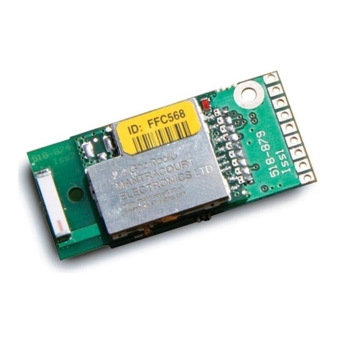
Mantracourt T24-SAf User manual

T24-SAf
Fast Strain Gauge Acquisition Module
User Manual
mantracourt.com

Mantracourt Electronics Limited T24-SAf Fast Strain Gauge Acquisition Module User Manual
1
Introduction / Overview ........................................................................................................2
Connections .......................................................................................................................2
Power.............................................................................................................................2
Input Connections ..............................................................................................................2
Strain Gauge..................................................................................................................2
Configuration......................................................................................................................3
Calibration .........................................................................................................................3
Installation ......................................................................................................................3
T24 Toolkit....................................................................................................................3
T24-BSu Base Station .......................................................................................................3
T24 Toolkit ......................................................................................................................4
General Pages ................................................................................................................4
Setup Base Station Communications .....................................................................................4
Home ..........................................................................................................................5
Analyser .......................................................................................................................6
Data Provider Monitor ......................................................................................................7
Information ...................................................................................................................8
Battery Life...................................................................................................................9
Battery and Radio Levels................................................................................................. 10
Battery and Radio Levels Advanced Settings ......................................................................... 11
Channel and Encryption .................................................................................................. 12
Save and Restore .......................................................................................................... 13
Data Provider Monitor .................................................................................................... 14
Advanced Settings ......................................................................................................... 15
Installation....................................................................................................................... 16
Overview....................................................................................................................... 16
Power Supply / Battery ..................................................................................................... 17
Considerations When Selecting Batteries ............................................................................. 17
Battery Types .............................................................................................................. 18
Power Supply Modules .................................................................................................... 18
Lithium Ion /Polymer Module T24-BC1.............................................................................. 18
Physical Connections ................................................................................................ 19
Specification .......................................................................................................... 19
Suitable Batteries .................................................................................................... 19
Capacitor Module T24-BC2 ............................................................................................ 20
Mounting ....................................................................................................................... 21
Antenna ........................................................................................................................ 22
Internal Chip Antenna .................................................................................................... 22
External Antenna Option ................................................................................................. 22
External Antennas ......................................................................................................... 23
Antenna Orientation ...................................................................................................... 23
Specifications ................................................................................................................... 24
General Radio................................................................................................................. 24
T24-SAf......................................................................................................................... 24
Approvals ........................................................................................................................ 24
CE ............................................................................................................................... 24
FCC.............................................................................................................................. 25
Industry Canada .............................................................................................................. 25
OEM / Reseller Marking and Documentation Requirements .......................................................... 26
FCC.............................................................................................................................. 26
IC ................................................................................................................................ 26
CE ............................................................................................................................... 26
Declaration Of Conformity ................................................................................................... 27
Worldwide Regional Approvals .............................................................................................. 28
Important Note ............................................................................................................ 28
Warranty ......................................................................................................................... 28

Mantracourt Electronics Limited T24-SAf Fast Strain Gauge Acquisition Module User Manual
2
Introduction / Overview
For high speed applications the T24-SAf provides measurements at 2KHz with 200 packets per second containing
10 x 32 bit values representing nano volts/volt.
The T24-SAf will usually be used in conjunction with an analog output module or for supplying data to a
computer via a base station.
Please note that these modules are not suitable for use with T24 handheld displays.
Connections
You will require a 3 Volt dc supply for the acquisition module which may be 2 X AA alkaline batteries.
Power
Attach power supply wiring to the module as shown below:
+ 3V Supply
0V Supply
Connect to a 3 Volt power supply or batteries.
WARNING: This module is not reverse polarity protected!
WARNING: The maximum voltage is 3.6V!
Input Connections
Strain Gauge
Strain gauge connection is 4 wire as follows:
+EXC
SHLD
-EXC
-SIG
+SIG
The resistance of the strain gauge can be between 85 and 5000 Ohms. The T24-SAf can support up to 4 350Ohm
strain gauges bridges attached in parallel (At the expense of reduced battery life).
The cable lengths between the T24-SAf and the gauges should be kept below 3 meters and generally as short as
possible.
As the measurement is 4 wire the longer the cable the more inaccurate the measurement from the factory
mV/V calibration will be due to voltage drops in the cable.
The cable should be of good quality and shielded at either the T24-SAf SHLD point and should not be connected
to the metal housing of the load cell.
The strain gauge measurement is bi-directional, i.e. tension & compression.

Mantracourt Electronics Limited T24-SAf Fast Strain Gauge Acquisition Module User Manual
3
Configuration
This section explains how to install software and configure the module. Please note that you will need the T24
Toolkit software and a T24-BS base station to allow your computer to communicate with T24 telemetry
devices.
Calibration
Please Note: The calibration feature is not available for the T24-SAf.
Installation
T24 Toolkit
To configure the devices we must use the T24 Toolkit software application. This can be downloaded from our
web site or may be shipped with your products.
Install this on a PC or laptop.
Run setup.exe and follow the prompts to install the software.
T24-BSu Base Station
If you have a USB version of the base station (T24-BSu) then you just need to plug this into a USB socket on your
PC. If you are using an alternative base station then please refer to the appropriate manual.

Mantracourt Electronics Limited T24-SAf Fast Strain Gauge Acquisition Module User Manual
4
T24 Toolkit
The T24 Toolkit provides a means of simple configuration of the acquisition module along with useful tools to
aid integration.
Run the T24 Toolkit software application.
General Pages
Setup Base Station Communications
Select USB as the interface and select 1 as the Base Station Address.
In the toolkit all items that can be changed by the user are coloured orange.
To change a value just click on the relevant orange item. You will then be presented with a new dialog window
allowing you to change the value.
This may use a slider, text box or list to allow your new value to be entered.
Click the Home button to attempt communications with the base station.
If no communications can be established the toolkit will remain on this page. You will need to check that the
base station is powered and that it is connected to the converter correctly.

Mantracourt Electronics Limited T24-SAf Fast Strain Gauge Acquisition Module User Manual
5
Home
We now have successful communications with the base station so we can now pair with our device or we can
select the Spectrum Analyser mode or Data Provider Monitor mode.
To connect to our device we will pair. This is achieved by power cycling the device. Pairing removes the need
to know the radio settings of the device you are connecting to and also ensures that it is in a suitable state for
configuration.
Pairing Procedure
Remove power from the acquisition module.
Click the Pair button on the toolkit.
You now have 10 seconds to re-apply power to the acquisition module.
If you connect successfully the toolkit will change to the Information page.
If the pairing fails try again.
NOTE: Pairing with the toolkit will not change the radio configuration settings of the connected device.

Mantracourt Electronics Limited T24-SAf Fast Strain Gauge Acquisition Module User Manual
6
Analyser
The analyser page is provided as a tool and will not normally be needed unless you plan to change channels and
want to find the best channel to select, or to diagnose poor communications issues.
This page shows the radio signal levels detected across all the channels available to the T24 series of devices.
Using this tool may help in detecting noisy areas and allow you to decide on which channels you may want to
use.
The above charts show the traffic from a Wi-Fi network and it can be seen to be operating over channels 6 to 9
and it would be best (though not essential) to avoid using these channels.

Mantracourt Electronics Limited T24-SAf Fast Strain Gauge Acquisition Module User Manual
7
Data Provider Monitor
NOTE
Prior to version 1.1.91 of the T24 Toolkit the value shown for a T24-SAf will look like random
characters because the data packet from the T24-SAf contains 10 values not just the normal single
value.
Version 1.1.91 and later will show the correct value but will only log at 200Hz.
To log at 2KHz please pair to the module and use the specific Data Provider Monitor page shown later
in this manual.
T24 acquisition devices normally operate in low power mode and periodically transmit Data Provider
packets
This page shows all detected Data Provider packets which may be useful for checking that a device is
operational.
NOTE: When the toolkit connects to a device to enable configuration it will usually inhibit the transmission of Data Provider packets.
The Start Logging button will ask for a filename and proceed to log the received data to a CSV file in the
following format:
Data Tag, Elasped mS, Value
The View Last Log button will launch the application associated with CSV files and open the last logged file.

Mantracourt Electronics Limited T24-SAf Fast Strain Gauge Acquisition Module User Manual
8
Information
Once successfully paired to a device this page is displayed.
This page shows you information about the connected device.
Items you can change:
Name
You can enter a short description which may help you recognise this device in the future.

Mantracourt Electronics Limited T24-SAf Fast Strain Gauge Acquisition Module User Manual
9
Battery Life
This page gives guides on achievable battery life.
Note that the battery life calculator is assuming the best case scenario which is at 20°C and that the battery
has a suitable low internal resistance or that a suitable capacitor is fitted across the battery. See battery
details in the Installation section.
Items you can change:
Battery Type
This is not a parameter of the device but information used by the battery life
guide. You can choose from some preset batteries or choose custom to allow
you to select your own battery capacity. See below. This will also offer to
change the Battery Low Level if the level suitable for the chosen battery is not
the level currently set.
Usable Capacity
This is not a parameter of the device but information used by the battery life
guide. This is the capacity of the battery in Amp Hours and has a profound
effect on battery life calculations. This capacity needs to be calculated from
battery manufacturer’s data sheets to take into account that we can only use
batteries down to 2.1 Volts so in the case of twin AA cells this would be 1.05
Volts.
Generally the usable capacity will not be as high as that advertised by the
battery manufacturer. Temperature and internal resistance of the battery are
not taken into account in the guide.
Sensor Impedance
This is only available for certain acquisition modules. This is not a parameter
of the device but information used by the battery life guide. Enter the
resistance of the connected strain gauge in Ohms.
Usage Per 24 Hour Period
Enter the number of hours per 24 hour period that the T24-SAf
will be turned on and communicating.

Mantracourt Electronics Limited T24-SAf Fast Strain Gauge Acquisition Module User Manual
10
Battery and Radio Levels
Here you can see the voltage of the battery and the radio signal levels at the base station and the remote
acquisition module. This simple view gives an LQI value which stands for Link Quality Indicator. This value will
range from 0 to 100 and within this band you should still achieve communications. As the level drops towards
zero communications may become intermittent but still achievable.
You can set the level at which the acquisition module reports a low battery.
If the battery voltage is below the Low Battery Level the bar will be coloured orange.
Items you can change:
Low Battery Level
Click this item to set the battery low level.
Clicking the Advanced button will give more detailed information on the RSSI and CV levels of the received
radio packets.

Mantracourt Electronics Limited T24-SAf Fast Strain Gauge Acquisition Module User Manual
11
Battery and Radio Levels Advanced Settings
LQI value which stands for Link Quality Indicator. This value will range from 0 to 100 and within this band you
should still achieve communications. As the level drops towards zero communications may become intermittent
but still achievable.
RSSI is effectively the received dB level which will range from about -30 which is a good signal to -90 which is a
weak signal.
CV is the correlation value and indicates how well the signal can be decoded. This ranges from 55 which is a
poor quality signal and 110 which is an excellent signal.

Mantracourt Electronics Limited T24-SAf Fast Strain Gauge Acquisition Module User Manual
12
Channel and Encryption
Here you can change the channel and encryption key for the acquisition module device.
Simply pair to the T24-SAf and change its channel and key.
Note that some devices such as the T24-AO1 analog output module will allow pairing to an acquisition module.
When pairing it will alter the T24-SAf settings to match those of the analog output module.
NOTE: Early acquisition module do not yet utilise the encryption keys so these should be left at all zeros.
Items you can change:
Channel
Select a channel between 1 and 16. The default is channel 1. You can use the
Spectrum Analyser mode to determine a good clean channel to use.
NOTE: Channel 16 is used to negotiate pairing so avoid this channel if possible.
Encryption Key
Only devices with identical encryption keys can communicate. You can isolate
groups of devices on the same channel or just use the key to ensure the data
cannot be read by somebody else.

Mantracourt Electronics Limited T24-SAf Fast Strain Gauge Acquisition Module User Manual
13
Save and Restore
Here you can save the device settings to a file on your PC so that they can be later loaded back into the same
or different device.
Items you can change:
Save
Click this button to open a file dialog window to allow you to select a filename
and location to save the configuration file to.
All configuration information including calibration data will be saved to the
file.
The file extension is tcf.
Restore
Click this button to open a file dialog window to allow you to select a filename
and location of a previously saved file to load into the connected device.
All configuration information including calibration data will be overwritten.
The file extension is tcf.
Advanced Settings
Click this button to enter the Advanced Settings Page.
Here are settings which do not normally require changing.

Mantracourt Electronics Limited T24-SAf Fast Strain Gauge Acquisition Module User Manual
14
Data Provider Monitor
Because the standard data provider monitor does not decode correctly the multiple data packets from as T24-
SAf this special page provides a trend chart and a view of all 10 readings contained in each packet.
It also shows a delta value (Max –min) and allows you to log the data to a file.
Items you can change:
Reset
Clicking here will reset the Delta display to zero.
Pause
Stop the module transmitting data.
Continue
Continue with data transmission.
Start Logging
Allows you to select a filename and starts to log the data to the selected file.
The format of the file is CSV and the columns are:
Elapsed,Value <carriage Return>
Where
Elapsed is a timestamp counter provided by the T24-SAf. Each unit represents
500uS and the number will reset to zero every 32.768 seconds. This timestamp
aids in spotting lapses in data and allows graphing data even with dropped
packets.
Value is the value logged.
The same button is used to stop the logging.
View Last Log
Once logging has stopped clicking this will open the log file in the program
associated with the .csv file extension.

Mantracourt Electronics Limited T24-SAf Fast Strain Gauge Acquisition Module User Manual
15
Advanced Settings
You should not normally need to change these settings.
Items you can change:
Sleep Delay
Here you can enter a delay in seconds after which the acquisition module will
return to deep sleep if no Keep Awake message is heard from another T24
module such as an analog output module. The default is 60 seconds.
Data Tag
The data transmitted by the acquisition module is marked with a Data Tag
which is a 2 byte hexadecimal code. By default this is set to the last 2 bytes of
the device ID (or to put it another way, the last 4 characters of the device ID).
If by some chance you had two acquisition module devices that would be
working on the same channel and had the same last 4 characters in their ID (1
in 65,535 chances) you may want to change the data Tag of one of the devices
and perform pairing again with the associated T24 module.
Shunt Cal
Allows turning on or off the application of a shunt cal resistor to the bridge
input.
You must remember to turn this off before exiting the Toolkit software.
nV/V
Shows the output value so the effect of the Shunt Cal can be seen.

Mantracourt Electronics Limited T24-SAf Fast Strain Gauge Acquisition Module User Manual
16
Installation
Overview
Radio performance at microwave wavelengths is very dependent upon the operating environment; any
structure within the operating region of the radios will give rise to three effects:
Obscuration. Obscuration will result in reduced range and occurs when an obstruction masks the line-of-sight
between radios.
Aberrations to the horizontal and vertical space patterns. Distortion of these patterns may occur if
structures or objects are placed in the near or intermediate field of the antenna. The effect will be to distort
the coverage patterns, adversely affecting range and link quality.
Reflection. Any object placed in line-of-sight of the transmit antenna will result in signals arriving at the
receiver by an indirect path. Degradation of performance due to reflection (multipath effects) appears as
reduced range or poor link quality.
Any of the above will cause poor RSSI figures, an increase in the packet loss rate and in extreme cases
complete loss of signal. Fortunately, if consideration is given to these effects at the integration stage then a
good quality link will be obtained.
Guidelines for product design:
When selecting materials for product enclosures, preference should be given to fibreglass, light coloured ABS or
Polypropylene; at the wavelength of 2.4GHz radio other materials will adversely affect the signal by
attenuation, refraction or change in polarisation.
If the application demands that the radio is fitted inside a metal enclosure then ensure that the specified
clearances are maintained around the antenna and design in a fibreglass RF window at least as large as the
clearance dimensions but ideally as large as possible.
RAD24i radios fitted inside a product should be oriented so that the chip antenna will be vertical when the
product is in its normal operating position.
Guidelines for installation:
When planning installations ensure that line-of –sight between nodes is maintained and that objects or
structures are kept at least one metre away from antennae wherever possible.
To avoid poor link quality between a RAD24i radio and a handheld device ensure that the RAD24i is mounted so
that the chip antenna is vertical. Improvement may also be obtained by altering the height above ground of the
RAD24i; a small increase or reduction in antenna elevation will often improve reception.
Range underwater is only a decimetre or so depending on packet rate. Best performance underwater is
obtained by using low packet rates and immersing water-proofed antennae rather than water-tight enclosures
containing the antennae.

Mantracourt Electronics Limited T24-SAf Fast Strain Gauge Acquisition Module User Manual
17
Power Supply / Battery
The acquisition module operates from 2.1 to 3.6 Volts dc so can be supplied from a variety of cells.
WARNING: It is important to note that the acquisition module is NOT reverse polarity protected!
WARNING: The maximum voltage is 3.6V!
Considerations When Selecting Batteries
Re-chargeable or replacement
This really depends on the application. Some applications where expected battery life with alkaline batteries
will be many years would probably not warrant the use of re-chargeable batteries. Re-chargeable batteries
have implementation issues such as how to connect to the charger, how to seal this connection if required, can
the batteries be re-charged at a convenient point in the operation of the device I.E between shifts and does
the voltage, when charging, exceed the maximum supply voltage of the acquisition module if so the inline
charging module will need to be fitted.
Required battery life
Driven by the application and mainly dependent on measurement rate and sample time. The operation would
normally require that the acquisition module is used in Low Power Mode to maximise battery life.
Size of
Choosing a battery will be influenced by how much space is available and what battery life is required,
generally the bigger the battery the longer it will last.
Operating temperature range
A batteries useable capacity is influenced by its operating temperature. Generally, the lower the temperature
the lower their ability to provide charge. Beware of the batteries specified operating range when considering a
particular battery technology.
Self discharge.
Batteries are chemical devices and have a shelf life which needs to be considered in application where long
battery life is required. Typically an Alkaline has a battery life of 5 years.
Internal Resistance of battery
Low internal resistance is important, the higher the resistance the less useful life of the battery is available.
This is due to voltage drops caused during the high current phase of the measurement cycle. In the case of a
T24-SAf strain gauge input module 300mA required for 250uS. Batteries with an internal resistance of less than
150mOhm will not require the additional inline capacitor module.
Connections to battery
For the same reasons internal resistance must be low it is important to keep any voltage drops from the battery
to the acquisition module as low as possible too. Care must be taken in selecting the connection method
between batteries and acquisition module. For example cables should be kept as short and thick as possible.
Environmental
Other considerations when selecting a connection method to the Batteries is the effect of vibration. A standard
battery holder is a poor choice in applications when the device can be subject to vibration. This is due to the
interruption of supply from the battery to the acquisition module caused when the spring arrangement holding
the battery to the terminal of the holder is defeated.
Corrosion of terminals must also be considered as this will also introduce resistance into the supply
connections. This could be overcome by ensuring the enclosure is sealed.
Optimising battery life
Battery life can be optimised by considering the following.
Use of low power mode.
Transmission interval.
Required Measurement resolution (Sample time).
Sleep / Wake configuration
Auto-Sleep duration.

Mantracourt Electronics Limited T24-SAf Fast Strain Gauge Acquisition Module User Manual
18
Battery Types
Battery Type
Notes
Alkaline
Zn-MnO2
Pairs of alkaline 1.5V cells are the most common. Use D cells for maximum
life and AA cells where space is restricted.
Example: Varta 4014 (D), Varta 4006 (AA)
Recommend T24-BC2 module to maximise usable capacity.
Nickel Metal Hydride
NiMh
Most cells are 1.2V so two in series gives 2.4 Volts. These can match
alkaline batteries in capacity but as the charged voltage is lower they do
not match the usable capacity. These batteries self discharge at a faster
rate than alkalines. If charging these cells in circuit precautions must be
taken to ensure that the maximum voltage on the acquisition module is
not exceeded.
Example: GP 270AAHC (AA)
Recommend T24-BC2 module to maximise usable capacity.
Nickel Cadmium
NiCad
Most cells are 1.2V so two in series gives 2.4 Volts. Three in series can be
used to give 3.6 Volts. These do not have the usable capacity of an
alkaline battery. These are generally only useful if they are to be charged
on a regular basis. If charging these cells in circuit precautions must be
taken to ensure that the maximum voltage on the acquisition module is
not exceeded.
Example:
Recommend T24-BC2 module to maximise usable capacity.
Lithium Primary 3.6V
Li-SOCl2
Lithium cells can be used but note that the maximum voltage is 3.6 Volts.
Select a cell with low internal resistance.
Example: Saft LS17500 (A), Saft LSH20 (D)
Recommend T24-BC1 module as these cells usually have a high internal
resistance.
Lithium Iron Disulphide
Li-FeS2
These can be found at 1.5 Volts and can therefore be a direct replacement
for Alkaline cells. The low internal resistance and high capacity make
these batteries an ideal choice.
Example: Energizer L91
Lithium Ion and Lithium Polymer
LiON, LiPo
These generally start at 3.7V and exceed the maximum allowable voltage.
These are usable if a regulator and charging circuit can be installed
between the acquisition module and the battery. Care must be taken here
that the regulator does not draw too much current when idle so that the
low power modes are not compromised.
Recommend T24-BC1 module.
Power Supply Modules
Lithium Ion /Polymer Module T24-BC1
The T24-BC1 is a battery charger and power supply suitable for the T24 range of 3V acquisition modules. The
T24 Battery Charger is designed to supply a constant 3.3V from a Li-ion Battery while also charging the battery
from an input voltage. The unit comes pre-configured to provide a charging current of 466mA suitable for
VARTA LIP653450. This module also supports additional batteries providing a charge current of 133mA via the
removal of the leaded resistor (non surface mount).

Mantracourt Electronics Limited T24-SAf Fast Strain Gauge Acquisition Module User Manual
19
Physical Connections
GND
Charging Current
Resistor Fitted 466mA
Resistor Removed 133mA
LED lights when supply voltage applied
GND
GND
Battery +
Voltage Out
Supply
Voltage
Specification
Parameter
Min
Typ
Max
Units
Supply Voltage
4.1
5
6
V
Regulated Voltage Output
-
3.3
-
V
Battery positive connection
-
3.7
-
V
Maximum Cable Length
-
150 *
mm
Quiescent Current
1.7
μA
* 07/02 gauge wire attached to maximum load i.e. T24-SAf with four 350 Ohm strain gauges
Note LED will only be lit when an input voltage is applied
Suitable Batteries
VARTA LIP653450
Rated Capacity: 1100mAh
Dimensions: 35 x 54 x 7 (mm)
Weight: 20g
Charge Time : 3 Hours @ 466mA
Battery life = 3.3 days*
VARTA LIC18650
Rated Capacity: 2200mAh
Dimensions: 18.25 Diameter 65mm Height
Weight: 46g
Charge Time : 4.5 Hours @ 466mA
Battery life = 6.5 days*
UBC 581730
Rated Capacity: 250mAh
Dimensions: 18 x 31.5 x 5.8 (mm)
Weight: 6.5g
Charge Time : 2 Hours @ 133mA
Battery life = 18 hours *
* Note: Battery life is calculated with a T24-SAf running for 2 hours out of every 8 hours, to a 1kΩ bridge.
Table of contents
Other Mantracourt Control Unit manuals
Popular Control Unit manuals by other brands
SUNTEC
SUNTEC MN Series Installation and operating instruction
Watts
Watts Ames 910GD-17 Installation operation & maintenance
Acromag
Acromag VPX6860 user manual
IME
IME Nemo 96HDLe Mounting instructions
Afag
Afag RE-50 Assembly and operating instructions
Bray
Bray FlowTek F15 Series Installation, operation and maintenance manual
