idronaut Ocean Seven 314 User manual


OCEAN SEVEN 314
Multi-parameter On-line module
Copyright @ 1982 –2019 Idronaut S.r.l. All rights reserved.
OCEAN SEVEN and Idronaut are registered trademarks of Idronaut S.r.l.
Other products and services mentioned in this document are identified by the trademarks or service marks of their respective companies
or organisations. No part of this publication, or any software included with it, may be reproduced, stored in a retrieval system, or
transmitted in any form or by any means, including photocopying, electronic, mechanical, recording or otherwise, without the prior
written permission of the copyright holder. Idronaut S.r.l. provides this document as is without warranty of any kind either expressed or
implied including, but not limited to, the implied warranties of merchantability and fitness for a particular purpose. Idronaut S.r.l. may
make changes of improvements in the equipment, software, firmware, or specifications described in this document at any time and
without notice. These changes may be incorporated in new releases of this document. This document may contain technical inaccuracies
or typographical errors. Idronaut S.r.l. waives responsibility of any labour, materials, or costs incurred by any person or party as a result
of using this document. Idronaut S.r.l. shall not be liable for any damages (including, but not limited to, consequential, indirect or
incidental, special damages, or loss of profits or data) even if they were foreseeable and Idronaut S.r.l. has been informed of their potential
occurrence arising out of or in connection with this document or its use.
IDRONAUT S.r.l.
Via Monte Amiata, 10 –Brugherio (MB) –ITALY
Tel. +39 039 879656 –883832 Fax. +39 039 883382

IDRONAUT –Brugherio (MB) OCEAN SEVEN 314 On-line module 04-2019
IMPORTANT REMARKS
INTERNAL BATTERY REPLACEMENT/RECHARGING
1) To gain access to the battery pack, remove the screws in the OS314 top cover. However,
before doing this, please ensure to have removed any water droplets around the screw
heads, to prevent them from running down inside the housing.
ON-LINE MODULE Top-Cover removal, please follow the instructions in
Appendix “A”
2) Rechargeable battery: disconnect the battery pack from the top cover and connect it
to the battery charger.
3) If the OS314 is not to be used for long periods (some months), remove the internal
battery pack from the OS314. This eliminates the possibility of damaging the electronic
circuitry in case of battery leaks because a small amount of energy is drawn from the
internal batteries by the OS314 electronic circuitry even if OFF. This phenomenon
causes batteries to run down and they may be damaged (leak) in a very long time
SELF-RECORDING USE
➢The ON-LINE MODULE internal Real-Time Clock (RTC) keeper is powered by the ON-LINE
MODULE main battery. If the battery run-off energy or is disconnected, the RTC loses date
& time. It is mandatory to set up the ON-LINE MODULE date & time or/and check that
the ON-LINE MODULE date & time are correct before starting a self-recording data
acquisition cycle.
➢The ON-LINE MODULE is equipped with a rotary magnetic power ON/OFF switch,
installed on the top cover. The ON-LINE MODULE is ON when the switching arm is
positioned over the red dot marker. Once the ON-LINE MODULE self-recording
configuration is completed, the ON-LINE MODULE can be switched OFF and then ON again
at the sampling site, when ready for the deployment. This procedure is indispensable to run
self-recording data acquisitions, as described in the dedicated section of this manual.
VERY IMPORTANT: Allow a 10-second interval between each ON/OFF cycle.
CONDUCTIVITY MEASUREMENT
➢To obtain the best accuracy, the conductivity sensor and therefore the ON-LINE MODULE
sensor head, must be immersed in clean seawater or freshwater for at least 15 minutes before
measurements.
➢When the conductivity sensor is not in use, it is kept dry. Therefore, when the conductivity
sensor is placed in water, very small bubbles may remain attached to the platinum ring
electrodes (seven). If such a thing happens, the measured value of conductivity will be lower
than the true one. To remove these air bubbles, degrease the inside of the conductivity cell
using cotton buds wetted with the Conductivity Sensor Cleaning Solution or with liquid soap.
Gently rotate the cotton bud against the whole internal surface of the quartz cell. This will
wet the platinum electrodes, thus reducing the surface tension of the cell and considerably
decreasing the risk of trapped air bubbles.
OXYGEN MEASUREMENT
Most polarographic oxygen sensors take 5 to 10 minutes after they have been switched on
to polarize and become stable. To overcome this limitation, the OS314 has been fitted with

IDRONAUT –Brugherio (MB) OCEAN SEVEN 314 On-line module 04-2019
a small internal rechargeable device, to maintain polarization of the oxygen sensor
continuously for about three days. However, if the OS314 is not used for several days, the
polarization device may become completely discharged. It is recommended that the OS314
should be switched ON (and streaming real-time data) for at least few minutes, to fully
recharge the polarization device in a healthy condition before starting the measurements.
BLUE CAP OPTICAL DISSOLVED OXYGEN SENSOR
A black cap is provided to protect the membrane from light. When the ON-LINE MODULE
is not used protect the membrane by installing the black cap.Please, remove the black cap
before calibration and before deploying the ON-LINE MODULE in water.
pH MEASUREMENT
The pH and reference sensors should never be allowed to dry out. For short-term storage of
up to one day, the OS314’s sensor head can simply be immersed in water. If the OS314
remains unused for periods longer than one day, always place the hydrating caps on both
sensors. The pH sensor cap should be filled with the pH7 Buffer Solution (or simply with
clean water). The reference sensor cap should be filled with the Idronaut Reference Sensor
Storage Solution.
ON-LINE MODULE CTD SENSORs RE-CALIBRATION & CHECKING
A dedicated Windows software described at section E.7.3 allows to correctly capture data
from the ON-LINE MODULE CTD sensor during a re-calibration procedure or ON-LINE
MODULE sensors performance checking cycle. Captured data can be saved in a txt file. The
“OceanSevenCalibration” software is freely distributed with the IDRONAUT ITERM
software.
OS314 WASHING
After use, the OS314 must be always washed with fresh water to remove any salt water
residual or dirtiness.

IDRONAUT –Brugherio (MB) OCEAN SEVEN 314 On-line module 04-2019
COPYRIGHT STATEMENT
Copyright IDRONAUT S.r.l.
OCEAN SEVEN and IDRONAUT are registered trademarks of IDRONAUT S.r.l. All rights reserved.
This document may not, in whole or in part, be copied, photocopied, reproduced, translated, or reduced to
any electronic medium or machine-readable form without prior consent in writing from IDRONAUT S.r.l.
ABOUT THIS MANUAL
This manual will serve as a guide to you when you use the OCEAN SEVEN 314
❖Use it to understand the purpose of each of the OS314 components and functions.
❖It will help you to understand the OS314 behaviour.
❖It will guide you through the OS314 capabilities.
❖It will serve you as a reference when some problems arise when using the OS314.
HOW TO USE THIS MANUAL
The following topics are covered by this manual:
Section 1 A description of the OCEAN SEVEN 314.
Section 2 Installation and start-up operations.
Section 3 Data acquisition functions and data processing capabilities.
Section 4 Data storage functions.
Section 5 Sensor calibration functions.
Section 6 Service functions (configuration, diagnostics).
Section 7 OS314 maintenance.
Section 8 Troubleshooting
Appendix A Internal and external battery pack description.
Appendix B Data Processing Function Priming.
Appendix C OPTIONAL Sensor
Appendix D Advanced configuration
Appendix E IDRONAUT Windows Terminal Emulation Programme.
Appendix F Wireless “Bluetooth™” –WiFi interface.
Appendix G Submersible connectors and cable care.
GETTING STARTED
To become familiar with the OCEAN SEVEN 314 ON-LINE MODULE capabilities and operation, we
suggest reading through sections 1 and 2. It is necessary to also read sections 3 and 5 and section 7 before
starting to deploy the OS314. The remaining sections and appendices could be consulted only when needed.
If the OS314 is supplied with external sensors, deck unit or the IDRONAUT Portable Reader, useful
information can be found in each dedicated Operator’s Manual.
Operator’s Manuals of all IDRONAUT products and software can be found on the USB-data storage key
included with this product in the “Literature&Manuals\OperatorManual” folder.
NOTATIONAL CONVENTIONS
Throughout this manual, the following conventions are used to distinguish the various elements of the text:
[OS314 COMMANDS] They always appear in uppercase and between [ ] or < > brackets.
OS314 messages, user inputs They always appear in italics.
DEFINITION OF TERMS
Throughout this manual, the following terms are used:
Cast As a whole of the data set collected in the same way in a determined
sampling point.
Data set As a whole of configured parameters expressed in physical or

IDRONAUT –Brugherio (MB) OCEAN SEVEN 314 On-line module 04-2019
chemical units and acquisition date and time, collected at
programmed sampling interval, (i.e. once per second, once per
depth increment).
Raw data –ADC Counts As a whole set of data acquired by means of the ADC and the
conditioning circuits, from the configured sensors and are
expressed in numeric decimal or hexadecimal format.
Non-verbose mode This term refers to a OS314 that has been configured to use a
communication protocol (computer oriented) to communicate with
the operator.
Verbose mode This term refers to a OS314 that has been configured to use the MMI
functions to communicate with the operator.
ON condition This term refers to a fully operative OS314, waiting for commands
from the operator or running the requested command.
OFF condition This term refers to a OS314 electronically switched off. In this state,
the OS314 draws negligible amount of current from the battery.
MMI This term refers to the set of common rules, which the operator must
follow during the operation of OS314 in verbose mode.
QAM Quadrature Amplitude Modulation.
IDRONAUT DOCUMENTS PERTAINING TO THE OCEAN SEVEN 314
The following documents are available in the “Literature & Manual” folder on the USB-data storage key
distributed with the OCEAN SEVEN 314 ON-LINE MODULE.
❖OCEAN SEVEN OS314s Data Transmission Protocol Description
❖REDAS-5 Condensed Manual
SOFTWARE UPDATES AND TECHNICAL SUPPORT
Please visit our website download area for software updates and technical support:
http://www.idronaut.it/download.
WARRANTY
The OCEAN SEVEN 314 ON-LINE MODULE is covered by a one-year limited warranty that extends to all
parts and labour and covers any malfunction that is due to poor workmanship or due to errors in the
manufacturing process. The warranty does not cover shortcomings that are due to the design, nor does it cover
any form of consequential damage because of errors in the measurements. If there is a problem with your
OCEAN SEVEN 314, first try to identify the problem by following the procedure outlined in the
troubleshooting section of this manual. Please contact your representative or IDRONAUT Sr.l. if the problem
is identified as a hardware problem or if you need additional help in identifying the problem. Please make
sure to contact IDRONAUT S.r.l. to obtain the relevant instructions before the OCEAN SEVEN 314 or any
module is returned to IDRONAUT (see cleaning instructions).
For systems under warranty, IDRONAUT S.r.l. will attempt to ship replacement parts before the
malfunctioning part is returned. We encourage you to contact us immediately if a problem is detected and we
will do our best to minimize the downtime. Every effort has been made to ensure the accuracy of this manual.
However, IDRONAUT S.r.l.makes no warranties with respect to this documentation and disclaims any
implied warranties of merchantability and fitness for a particular purpose. IDRONAUT S.r.l.shall not be liable
for any errors or for incidental or consequential damages in connection with the furnishing, performance or
use of this manual or the examples herein. The information in this document is subject to change without
notice.
CLEANING INSTRUCTIONS
Before the returned OCEAN SEVEN 314 can be serviced, equipment exposed to biological, radioactive, or
toxic materials must be cleaned and disinfected. Biological contamination is presumed for any instrument,
OS314, or other device that has been used with wastewater. Radioactive contamination is presumed for any

IDRONAUT –Brugherio (MB) OCEAN SEVEN 314 On-line module 04-2019
instrument, OS314 or other device that has been used near any radioactive source. If an OCEAN SEVEN 314,
or other part is returned for service without following the cleaning instructions, and if in our opinion it
represents a potential biological or radioactive hazard, our service personnel reserve the right to withhold
service until appropriate cleaning, decontamination has been completed.
When service is required, either at the user's facility or at IDRONAUT, the following steps must be taken to
insure the safety of our service personnel.
➢In a manner appropriate to each device, decontaminate all exposed surfaces, including any containers.
70% isopropyl alcohol or a solution of 1/4 cup bleach to 1-gallon tap water are suitable for most
disinfecting. Instruments used with wastewater may be disinfected with 5% Lysol if this is more
convenient to the user.
➢The user shall take normal precautions to prevent radioactive contamination and must use
appropriate decontamination procedures should exposure occur. If exposure has occurred, the
customer must certify that decontamination has been accomplished and that no radioactivity is
detectable by survey equipment.
➢Any product being returned to the IDRONAUT S.r.l. laboratory for service or repair should be packed
securely to prevent damage.
➢Cleaning must be completed on any product before returning it to IDRONAUT S.r.l.
DISPOSAL OF WASTE EQUIPMENT BY USERS IN THE EUROPEAN UNION
The recycling bin symbol on the product or on its packaging indicates that this product must not be disposed
of with your other waste. It is your responsibility to dispose of your waste equipment by handling it over to a
designated collection point for the recycling of waste electrical and electronic equipment. The separate
collection and recycling of your waste equipment at the time of disposal will help to conserve natural resources
and ensure that it is recycled in a manner that protects human health and the environment. For more
information about where you can drop off your waste equipment for recycling, please contact your local city
office, your waste disposal service.

IDRONAUT –Brugherio (MB) OCEAN SEVEN 314 On-line module 04-2019
TABLE OF CONTENTS
1INTRODUCTION .............................................................................................................................. 1
1.1 OS314 DESCRIPTION ....................................................................................................................... 1
1.2 SAMPLING MODES.......................................................................................................................... 1
1.3 REAL-TIME COMMUNICATIONS ................................................................................................ 2
1.4 WIRELESS COMMUNICATION MODULE "BLUETOOTH®”, “WiFi”................................... 2
1.5 INTERNAL BATTERIES ................................................................................................................... 2
1.6 MAGNETIC POWER ON/OFF SWITCH........................................................................................ 2
1.7 MANAGEMENT PROGRAMMES.................................................................................................. 2
1.8 STANDARD SENSOR SPECIFICATIONS ..................................................................................... 3
1.9 OPTIONAL SENSOR SPECIFICATIONS....................................................................................... 3
1.10 ELECTRONIC SPECIFICATIONS................................................................................................... 3
1.11 PHYSICAL CHARACTERISTICS .................................................................................................... 4
1.12 THE STANDARD SENSORS............................................................................................................ 4
1.12.1 LIFETIME AND HOW TO REPLACE THE IDRONAUT SENSORS......................................... 4
1.12.2 The pressure sensor........................................................................................................................... 4
1.12.3 The temperature sensor .................................................................................................................... 5
1.12.4 The conductivity sensor equipped with the "IDRONAUT seven-ring cell".............................. 5
1.12.5 The oxygen sensor ............................................................................................................................. 6
1.12.6 The oxygen sensor maintenance-free version - 5 bar only.......................................................... 7
1.12.7 The Blue-cap optical dissolved oxygen sensor.............................................................................. 7
1.12.8 pH and reference sensors ................................................................................................................. 9
1.12.9 The redox sensor.............................................................................................................................. 11
1.13 CALCULATIONS............................................................................................................................. 12
1.13.1 Polarographic Oxygen sensor ........................................................................................................ 12
1.13.2 pH calculation and pH correction in relation to the sample temperature............................... 12
1.13.3 Conductivity compensated at 20 °C.............................................................................................. 13
1.14 FIRMWARE OVERVIEW................................................................................................................ 14
1.14.1 User interface.................................................................................................................................... 14
1.14.2 Menu & submenu structure ........................................................................................................... 15
1.14.3 Menu header structure.................................................................................................................... 15
1.14.4 OS314 Access Rights........................................................................................................................ 16
1.14.5 Data transmission protocol ............................................................................................................ 16
1.14.6 Data transmission protocol: PTP Point-to-point ......................................................................... 16
1.14.7 Acquired data processing and post-processing .......................................................................... 17
1.14.8 Low power consumption................................................................................................................ 17
1.14.9 Configuration ................................................................................................................................... 17
2INSTALLATION AND START UP............................................................................................... 19
2.1 SHIPPING LIST ................................................................................................................................ 19
2.1.1 RS232C connection cable ................................................................................................................ 19
2.2 INSTALLATION .............................................................................................................................. 19
2.2.1 Internal battery................................................................................................................................. 19
2.2.2 Measuring flow cell ......................................................................................................................... 19
2.3 START-UP ......................................................................................................................................... 20
2.3.1 RS232C interface - OS314 power ON............................................................................................ 20

IDRONAUT –Brugherio (MB) OCEAN SEVEN 314 On-line module 04-2019
2.3.2 Standard start-up messages ........................................................................................................... 20
2.4 THE MAIN MENU .......................................................................................................................... 21
2.5 LOW POWER CONSUMPTION.................................................................................................... 21
3DATA ACQUISITION .................................................................................................................... 23
3.1 THE DATA ACQUISITION MENU.............................................................................................. 23
3.2 ACQUIRED PARAMETERS........................................................................................................... 23
3.3 COMMON RULES TO SET UP THE DATA ACQUISITION CYCLE...................................... 23
3.4 COMMMON RULES TO STORE ACQUIRED DATA................................................................ 23
3.5 ON-LINE ACKNOWLEDGEMENT.............................................................................................. 24
3.6 UNATTENDED ACKNOWLEDGEMENT .................................................................................. 24
3.7 UPLOADING DATA STORED IN THE On-Line module MEMORY...................................... 24
3.8 UNATTENDED ACQUISITIONS –IMPORTANT TIPS............................................................ 25
3.8.1 Power consumption reduction....................................................................................................... 25
3.8.2 Warm-up........................................................................................................................................... 25
3.8.3 ON/OFF cycles ................................................................................................................................. 25
3.9 SHIPPING CONDITIONS .............................................................................................................. 25
3.10 SENSORS........................................................................................................................................... 25
3.11 REAL TIME DATA ACQUISITION .............................................................................................. 25
3.12 TIMED DATA ACQUISITION....................................................................................................... 26
3.12.1 Terminate a timed data acquisition............................................................................................... 27
3.12.2 Automatic power OFF procedure ................................................................................................. 27
3.12.3 Accidental power ON cycle............................................................................................................ 28
3.12.4 Magnetic power ON/OFF switch................................................................................................... 28
3.12.5 Step-by-step procedure................................................................................................................... 28
3.13 CONDITIONAL DATA ACQUISITION ...................................................................................... 29
3.13.1 Terminate the Conditional data acquisition ................................................................................ 30
3.14 CONTINUOUS DATA ACQUISITION........................................................................................ 31
3.14.1 Step-by-step procedure................................................................................................................... 32
3.14.2 Routine operations to perform unattended continuous profiles .............................................. 32
3.14.3 Terminate the Continuous data acquisition................................................................................. 33
3.15 BURST DATA ACQUISITION ....................................................................................................... 33
3.15.1 Field operations................................................................................................................................ 34
3.15.2 Ending the unattended data acquisitions..................................................................................... 34
4DATA STORAGE............................................................................................................................. 35
4.1 MEMORY ORGANIZATION......................................................................................................... 35
4.1.1 Cast area............................................................................................................................................ 35
4.1.2 Data records...................................................................................................................................... 35
4.1.3 Data Sets............................................................................................................................................ 35
4.2 MEMORY MANAGEMENT........................................................................................................... 36
4.3 SHOW MEMORY STATUS ............................................................................................................ 36
4.4 SHOW STORED DATA................................................................................................................... 36
4.5 MEMORY DELETE DATA ............................................................................................................. 37
4.6 INITIALIZE DATA MEMORY....................................................................................................... 37
5SENSOR CALIBRATION ............................................................................................................... 39
5.1 CALIBRATION STORING LAYOUT............................................................................................ 39
5.1.1 Parameter/Sensor logical codes ..................................................................................................... 39
5.2 CALIBRATION GLP (GOOD LABORATORY PRACTICE)...................................................... 39
5.3 SENSOR CALIBRATION FUNCTIONS....................................................................................... 39

IDRONAUT –Brugherio (MB) OCEAN SEVEN 314 On-line module 04-2019
5.3.1 Updating the calibration information........................................................................................... 40
5.4 CALIBRATE THE SENSORS.......................................................................................................... 40
5.4.1 Selecting a wrong sensor ................................................................................................................ 40
5.5 CUSTOMIZED CALIBRATION PROCEDURE........................................................................... 40
5.5.1 Pressure sensor................................................................................................................................. 41
5.5.2 Temperature & Conductivity sensor calibration......................................................................... 41
5.5.3 Simple check of conductivity sensor calibration......................................................................... 42
5.5.4 Oxygen sensor calibration .............................................................................................................. 42
5.5.5 pH sensor calibration ...................................................................................................................... 45
5.5.6 Redox sensor calibration................................................................................................................. 46
5.6 CALIBRATING LOGGING ............................................................................................................ 50
6SERVICE, DIAGNOSTICS AND CONFIGURATION ............................................................... 51
6.1 THE SERVICE MENU ..................................................................................................................... 51
6.1.1 Raw data acquisition in ADC counts or mV................................................................................ 51
6.1.2 OS314 diagnostic functions ............................................................................................................ 51
6.1.3 OS314 configuration ........................................................................................................................ 53
7OS314 MAINTENANCE................................................................................................................. 58
7.1 OXYGEN SENSOR........................................................................................................................... 58
7.1.1 Important remark on oxygen measurement ................................................................................ 58
7.1.2 Green membrane ............................................................................................................................. 58
7.1.3 Refilling oxygen sensor cap with electrolyte ............................................................................... 59
7.1.4 Membrane replacement (oxygen membrane cap)....................................................................... 59
7.1.5 Replacement of membrane(s) using the OXYGEN SENSOR MAINTENANCE KIT: ........... 59
7.1.6 Oxygen sensor cleaning .................................................................................................................. 60
7.1.7 Oxygen sensor check in the absence of oxygen........................................................................... 61
7.1.8 BLUE CAP MEMBRANE STORAGE............................................................................................ 61
7.1.9 BLUE CAP DEPLOYMENT ........................................................................................................... 61
7.1.10 BLUE CAP CLEANING.................................................................................................................. 61
7.2 REFERENCE SENSOR..................................................................................................................... 61
7.3 pH SENSOR ...................................................................................................................................... 62
7.3.1 To etch the sensor, perform the following: .................................................................................. 62
7.3.2 Important remark on the pH measurement................................................................................. 62
7.4 CONDUCTIVITY SENSOR............................................................................................................. 63
7.4.1 Important remarks on conductivity measurement..................................................................... 63
7.4.2 Conductivity sensor cleaning......................................................................................................... 63
7.5 REDOX SENSOR.............................................................................................................................. 63
7.6 TEMPERATURE SENSOR .............................................................................................................. 63
7.7 PRESSURE SENSOR ........................................................................................................................ 63
7.8 INTERNAL BATTERY .................................................................................................................... 64
7.8.1 Internal battery pack endurance.................................................................................................... 64
7.8.2 Oxygen sensor polarization device ............................................................................................... 64
7.9 ROUTINE MAINTENANCE SCHEDULE ................................................................................... 64
8TROUBLESHOOTING.................................................................................................................... 65

IDRONAUT –Brugherio (MB) OCEAN SEVEN 314 On-line module 04-2019
APPENDIX
Appendix A Internal & external battery pack description 66
Appendix B Data Processing Function Priming 67
Appendix C Optional sensors 69
Appendix D Advanced configuration 71
Appendix E IDRONAUT Windows Terminal Emulation Programme 73
Appendix F Wireless “Bluetooth™” Interface 74
Appendix G Submersible connectors and cable care 75

SECTION ONE –SYSTEM DESCRIPTION
IDRONAUT –Brugherio (MB) OCEAN SEVEN 314 On-line module 04-2019
1
1INTRODUCTION
This section describes the main components of the OCEAN SEVEN 314 multi-parameter on-line module.
1.1 OS314 DESCRIPTION
The OS314 On-line module is housed in a sealed POM cylinder provided with a transparent acrylic flow
cell which is easily removed for sensor cleaning and maintenance. The sample volume of the measuring
chamber is only 450 ml, which ensures a very fast response time. The measurement sensors installed in
the On-line module are manufactured by IDRONAUT. The On-line module is controlled by an
advanced miniaturized and very low power electronics that store measurements in non-volatile
memory or transmit them in real-time at sampling rate of up to 28 Hz. The On-line module can be
directly connected to a data logger or personal computer by means of a wired or wireless interface.
Optional interfaces allow the connection of external fluorometer, turbidity meter and a remote
thermometer.
The OCEAN SEVEN 314 is equipped with the well-known and proven IDRONAUT pressure balanced
full ocean depth, pump free and long-term stability sensors. Central to which, is the high accuracy
seven-platinum-ring conductivity sensor, which can be cleaned in the field without the need for re-
calibration. Furthermore, an optional UV-LED (280nm) integrated into the conductivity cell, sterilize
the sample under measurement, thus avoiding the early growth of biofouling inside the quartz
measuring cell. For added flexibility, the OCEAN SEVEN 314 on-line module multi parameter OS314
can be operated in either verbose or non-verbose modes, the latter being especially convenient for
system integrations on buoys data loggers. Data is output using the standard RS232C interface, in
alternative the wireless (Bluetooth, WiFi) interface can be optionally installed. Submersible bulkhead
connectors, installed on the top cover, provide optional external power supplies and data exchange with
a suitable system. The response time constant is 50ms for the CTD sensors and 3/5s for oxygen, pH and
redox (see sensors specification table). Software compensation is provided for changes in the internal
temperature of the on-line, to guarantee both high performance and long-term stability. The electronic
boards are fitted in a sealed housing made of either PPS white plastic.
The OCEAN SEVEN 314 on-line module in its basic configuration is equipped with three sensors:
pressure, temperature and conductivity. Other bulkhead sensors can be optionally added, like:
dissolved polarographic oxygen, optical dissolved oxygen, pH, redox, reference electrode. It is possible
to interface external sensors or equipment like: a second remote temperature sensor, Turbidity meter,
Fluorometers.
The following equipment is currently interfaced:
❖IDRONAUT –Blue Cap Dissolved Oxygen sensor.
❖IDRONAUT –Remote temperature sensor.
❖CHELSEA - Unilux and Trilux Fluorometers.
❖SEAPOINT - Fluorometers.
❖TURNER DESIGNS –Cyclops-7 Fluorometers.
Other equipment or sensors can be interfaced upon request.
1.2 SAMPLING MODES
The OS314 is microprocessor-controlled and can be programmed to acquire and process data by various

SECTION ONE –SYSTEM DESCRIPTION
IDRONAUT –Brugherio (MB) OCEAN SEVEN 314 On-line module 04-2019
2
methods. Processed or raw data can be either transmitted in real time or stored inside the instrument.
Data acquisition methods includes:
➢Timed.The OS314 collects a series of samples and then sleeps for the configured time interval
before waking up again and repeating the acquisitions. Time interval can be configured from 5s
up to 1 day. Battery power is conserved while the OS314 is in sleep mode.
➢Conditional. Data is sampled at configurable sampling rates starting when the selected parameter
overcomes the configured boundary. Sampling continues until the selected parameter falls below
the configured boundary. Whenever the acquisition cycle starts, a configurable sampling rate
0.1..28Hz is used. Monitoring of the selected parameter occurs at the configurable interval
between 5s up to 1 day.
➢Continuous. Data is sampled at configurable sampling rates starting when the operator switches
on the OS314. Sampling continues until the OS314 is switched off. Multiple cycles can be obtained
by switching the ON-LINE MODULE ON and OFF.
➢Burst. Burst sampling carried out at configured intervals: 5s up 1 day.
➢Real-time.Data is sent to the control system at the chose sampling rates.
1.3 REAL-TIME COMMUNICATIONS
The OCEAN SEVEN 314 multi-parameter on-line module communicates with a computer via a
standard RS232C interface. Real-time data can be acquired by means of the REDAS-5 Windows software.
The RS232C cable maximum length is 200 m. It is important to mention that the OCEAN SEVEN 314 is
insulated with respect to the communicating device, independently of the kind of interface that is used.
Insulation guarantees that the sensors are not affected or disturbed by ground loops or stray currents.
1.4 WIRELESS COMMUNICATION MODULE "BLUETOOTH®”, “WiFi”
The OCEAN SEVEN 314 can be optionally equipped with a wireless adapter which allows bidirectional
full-duplex communications between the OCEAN SEVEN 314 and a personal computer (Desktop,
Laptop) or PDA devices equipped with a compatible wireless device. A thorough description of the
wireless adapter can be found in the dedicated appendix.
1.5 INTERNAL BATTERIES
The OCEAN SEVEN 314 housing has in its upper part enough space to accommodate an internal battery
pack. This is used whenever the OS314 carry-out unattended acquisition cycles without the connection
in real time with a surface unit (PC). Different types of battery can be installed inside the housing:
➢1x Size “A” Li-SOCI2 Lithium-thionyl chloride non rechargeable battery 3.6V, 2.4Ah
➢3x Size “AA” 1.5V Alkaline non rechargeable battery assembled in a single pack 4.5V
➢1x Size “C” Li-SOCI2 Lithium-thionyl chloride non rechargeable battery 3.6V, 8.4Ah
➢1x Li-Ion rechargeable IDRONAUT custom battery pack 3.7V,4.5 Ah
Whenever the OS314 operates in Timed, Burst and Conditional modes, the battery endurance is
considerably extended because the on-line module enters a deep sleep mode between acquisitions.
When the OS314 is not used for long periods (e.g. 2 weeks or more), we suggest disconnecting the
internal battery pack connector from the OS314 electronics or removing the internal battery pack from
the OS314 to prevent the internal batteries from damaging the OS314 due to battery acid leakage.
1.6 MAGNETIC POWER ON/OFF SWITCH
The OCEAN SEVEN 314 is equipped with a magnetic power ON/OFF switch,
which allows the operator to effectively switch ON and OFF the on-line
module. The on-line module switch on and off by itself whenever it performs
self-recording acquisition cycles and uses the internal battery pack.
When switching ON/OFF the OS314 by means of the magnetic switch, please
wait at least 10 seconds between consecutive ON/OFF cycles.
1.7 MANAGEMENT PROGRAMMES
IDRONAUT programmes designed for the Windows 32/64bit operating systems allow the operator to

SECTION ONE –SYSTEM DESCRIPTION
IDRONAUT –Brugherio (MB) OCEAN SEVEN 314 On-line module 04-2019
3
communicate with the OCEAN SEVEN 314 to perform attended or unattended data acquisitions.
Programmes include functions to upload data from the internal non-volatile data memory when the
OS314 acts as a logger. The available programmes are:
ITERM –WTERM:
IDRONAUT Terminal Emulation program and on-line module management to easily
communicate with the OCEAN SEVEN 314 multi-parameter OS314. Diagnostic and
dedicated functions are present.
REDAS-5: Real-time data acquisition, processing and presentation program, which allows the
numerical display and plotting of the standard sensors and the derived variables such as
salinity, sound speed, density, according to the UNESCO formulas and recommendations.
1.8 STANDARD SENSOR SPECIFICATIONS
The OS314 multiparameter on-line module can be equipped with the following sensors to measure:
1.9 OPTIONAL SENSOR SPECIFICATIONS
Among others, the OCEAN SEVEN 314 can be optionally equipped with the following sensors:
1.10 ELECTRONIC SPECIFICATIONS
Real-time and logging: up to 28 Hz
Interfaces RS232C, Wireless: WiFi/Bluetooth
Real-time clock accuracy: 3 ppm/year
Power supply: Battery: 2.9..5.0 VDC; running: 90 mA @ 3.6VDC; standby 8 µA @3.6VDC
External power: 9..32 VDC; running: 67 mA @ 12VDC; standby 8 mA @12VDC
Parameter Range Accuracy Resolution Time Constant
Pressure 0..10 dbar 0.05 % FS 0.0015 % FS 50 ms
Temperature -5..+50 °C 0.0015 °C 0.0001 °C 50 ms
Conductivity salt water 0..90 mS/cm 0.0015 mS/cm 0.0001 mS/cm 50 ms (1)
fresh water 0..7000 µS/cm 5 µS/cm 0.1 µS/cm 50 ms (1)
Oxygen (polarographic) 0..50 ppm 0.1 ppm 0.01 ppm 3 s 2)
0..500 %sat. 1 %sat. 0.1 %sat. 3 s 2)
Oxygen (optical) 0..45 mg/l 0.1 mg/l 0.025 mg/l 5 s
0..250 %sat. ±0.2 %sat. 0.05 %sat. 5 s
pH 2..12 pH 0.01 pH 0.1 mpH 3 s 3)
Redox -1000..+1000 mV 1 mV 0.1 mV 3 s
(1) At 2 litre/min flow rate. (2) From nitrogen to air. (3) Differential pH preamplifier, 10131014 ohm input impedance.
The fundamental properties of seawater like: Salinity, Sound Speed, Water Density, Oxygen ppm are obtained using the algorithms described
in the UNESCO “Technical papers in marine science no. 44”. The fresh water properties like: TDS (Total Dissolved Solids), Fresh Water
Conductivity corrected at 20°C and 25°C are automatically calculated.
Parameter Range Accuracy Resolution Time Constant
Remote temperature sensor -3..+50 °C 0.01 °C 0.001 °C 3s
Turbidity meter 0..>2500 FTU 0.1 FTU 0.025 FTU 3s (1)
Fluorometer 0..150 µg/l 0.02 µg/l 0.01 µg/l 3s (1)
UNILUX (single-channel) 0..100 µg/l (2)
TRILUX (three-channel) 0..100µg/l (2)
CYCLOPS fluorometers 0..100 µg/l (2)
(1) Provided with auto-range ,25,125,500, >2500 FTU; 5,15,50,150 µg/l.
(2) Chlorophyll a, Phycocyanin, Phycoerythrin for algae monitoring; Rhodamine WT or Fluorescein for dye tracing applications;
Nephelometer for turbidity monitoring.

SECTION ONE –SYSTEM DESCRIPTION
IDRONAUT –Brugherio (MB) OCEAN SEVEN 314 On-line module 04-2019
4
1.11 PHYSICAL CHARACTERISTICS
Fluidics Flow cell volume: 450 ml
Fluidic ports: male connector ¼” OD x 1/8” MT PVDF for hard tubes
Type of tubes: Tygon B-44-3 BEV grade tubing
Size of tubes: ¼” OD and 1/8” ID
Flow rate: ~ 2 litre/minute
Working pressure: 0.02 up to 1 bar
Dimensions: sealed container: POM cylinder Ø 75mm x 400mm (including bulkhead connectors)
Measuring chamber: Acrylic transparent Ø 100mm x 170mm
Weight: 3.5 Kg
Bulkhead connectors: wet-pluggable MCBH-6-MP
1.12 THE STANDARD SENSORS
This section provides a detailed presentation of the OCEAN SEVEN sensors.
LIFETIME AND HOW TO REPLACE THE IDRONAUT SENSORS
The IDRONAUT sensors are all pressure compensated and, in particular, the physical sensors (pressure,
temperature and conductivity) can last many years, if properly used. They are high-quality sensors, as
they are well known by oceanographers to measure salinity with great accuracy. If thoroughly
maintained by their respective hydrating caps and solutions, the IDRONAUT pH and reference sensors
can last several years. The sensor replacement requires that the closure screws on the top head of the
OS314 be unscrewed with a common screwdriver and the cylindrical housing be removed (this takes
very few minutes). The wire sensors are tin soldered on their respective connection points placed on the
printed circuit board. All sensor heads have a standard 12 mm diameter and are provided with two O-
rings (Parker 12-2) for sealing. This means that every sensor can be fitted in any of the five sensor head
holes. The pressure sensor is a high-quality transducer, which lasts many years if properly used. Its
replacement is not very easy and, moreover, it requires a Dead Weight Tester System to obtain the
factory calibration accuracy of 0.05% full scale.
The pressure sensor
The pressure sensor is a high quality strain gauge, centrally mounted on the OS314 base, capable of
generating a linear signal output, thus giving a resolution of 0.03% over the whole measuring range of
0 - 10 dbar
Type: strain gauge
Measurement range: 0...10 dbar
Accuracy: 0.05%FS
Resolution 0.002%FS
Response time: 50 ms @1 m/s
Measurement bridge resistance: @ 25°C Ω 3500 ± 20%
Excitation current: 0.6 mA
Insulation: @ 50 VCC MΩ 100
Operating temperature: °C -30…100
Sensor body: AISI 316L
Compensation: automatic compensation for temperature variations; not
compensated for the barometric pressure variations.
Life: unlimited.
Calibration frequency: monthly.
Maintenance: offset calibration in air.
SECTION ONE –SYSTEM DESCRIPTION
IDRONAUT –Brugherio (MB) OCEAN SEVEN 314 On-line module 04-2019
5
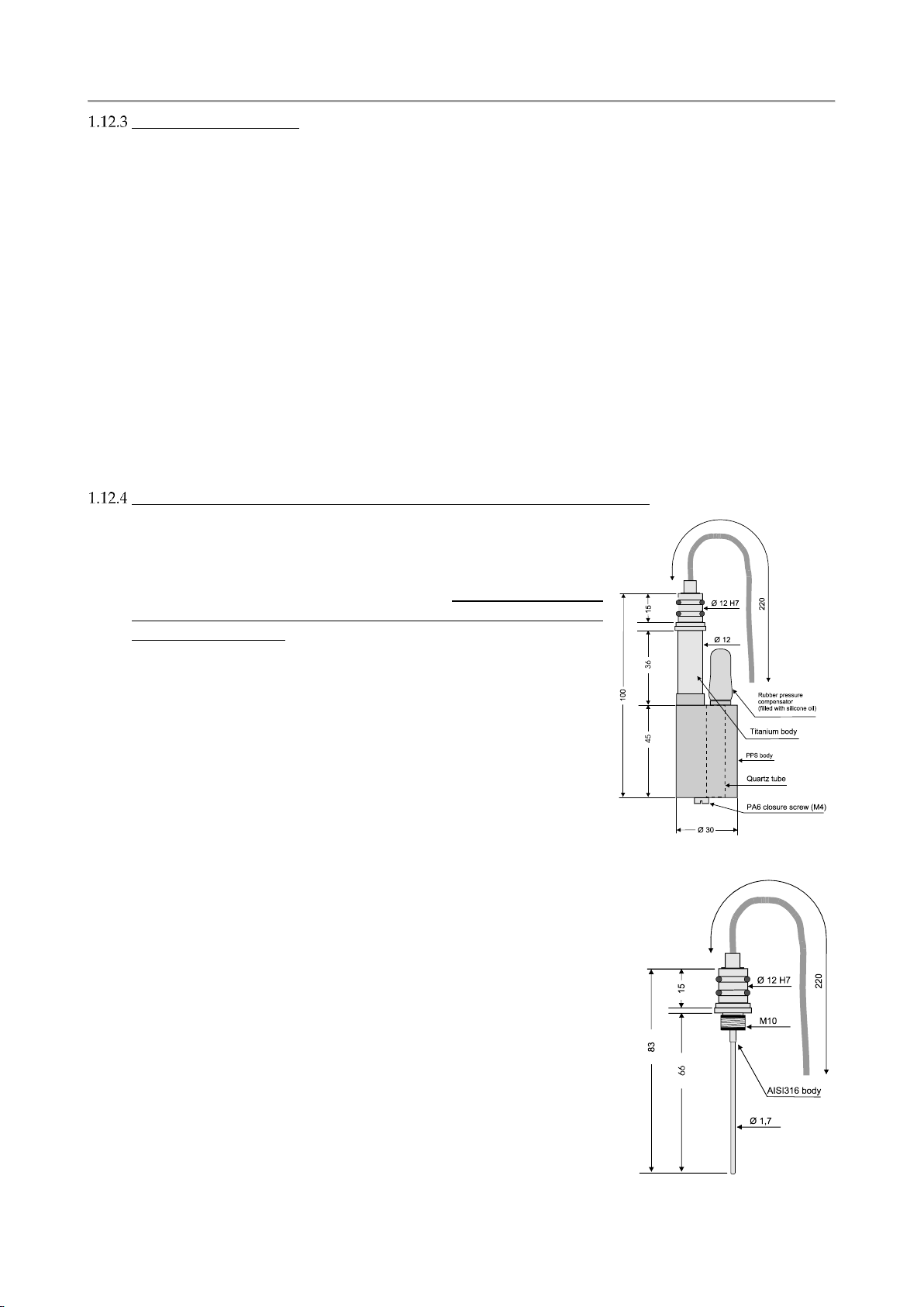
The temperature sensor
The temperature sensor consists of a platinum resistance thermometer (type Pt 100 ohms at 0°C), fitted
on a thin stainless-steel housing, able to withstand up to 700 bar. The sensor has a very low response
time (50 ms) and a high stability of reading with ageing. The drift of reading (sensor plus associated
electronics) is less than 0.0003 °C per year.
Type: Pt100@0°C
Measurement range: -3..+50 °C
Accuracy: 0.003 °C
Resolution: 0.0002 °C
Response time: 50 ms @1 m/s
Maximum pressure: 700 bar
Sensor body: AISI 316L
Life: unlimited
Calibration frequency: yearly
Compensation: none.
Maintenance: none.
The conductivity sensor equipped with the "IDRONAUT seven-ring cell"
The conductivity sensor is a unique flow-through self-flushed cell
with seven platinum ring electrodes. The central ring is excited with
alternate current flowing to both the outermost rings. The two
adjacent pairs of rings sense the relative drop in voltage due to the
electrical conductivity of the measured water. The outermost pair of
rings is grounded to shield the measuring cell from any outside
electrical interference. The cell is mounted in a special cylindrical
plastic body, which guarantees thermic insulation and is filled with
silicone oil and provided with a rubber bellow to achieve pressure
compensation. The IDRONAUT conductivity sensor and its
associated electronics are designed to work both with plain and black
platinised platinum electrodes These electrodes have the advantage
that, they can be used in both clean and dirty water without the fear
of contamination. Should electrode contamination occur, they can be
easily cleaned (even with up to 30% hydrochloric acid) without
affecting the OS314 performance or requiring re-calibration.
Measurement cell: 7 platinum rings deposited inside a quartz tube. Internal diameter
8mm, length 45mm.
Measurement range: 0..70 mS/cm
Accuracy: 0.003 mS/cm
Resolution: 0.0003 mS/cm
Response time: 50 ms @1 m/s
Max pressure: 700 bar
Sensor body: black plastic and titanium
Compensation: automatic compensation of the
pressure and thermal effect on the
cell geometry are performed by the
acquisition software.
Life: unlimited.
Calibration frequency: yearly.
Maintenance: cleaning using the IDRONAUT
“Conductivity sensor cleaning
solution”.
SECTION ONE –SYSTEM DESCRIPTION
IDRONAUT –Brugherio (MB) OCEAN SEVEN 314 On-line module 04-2019
6
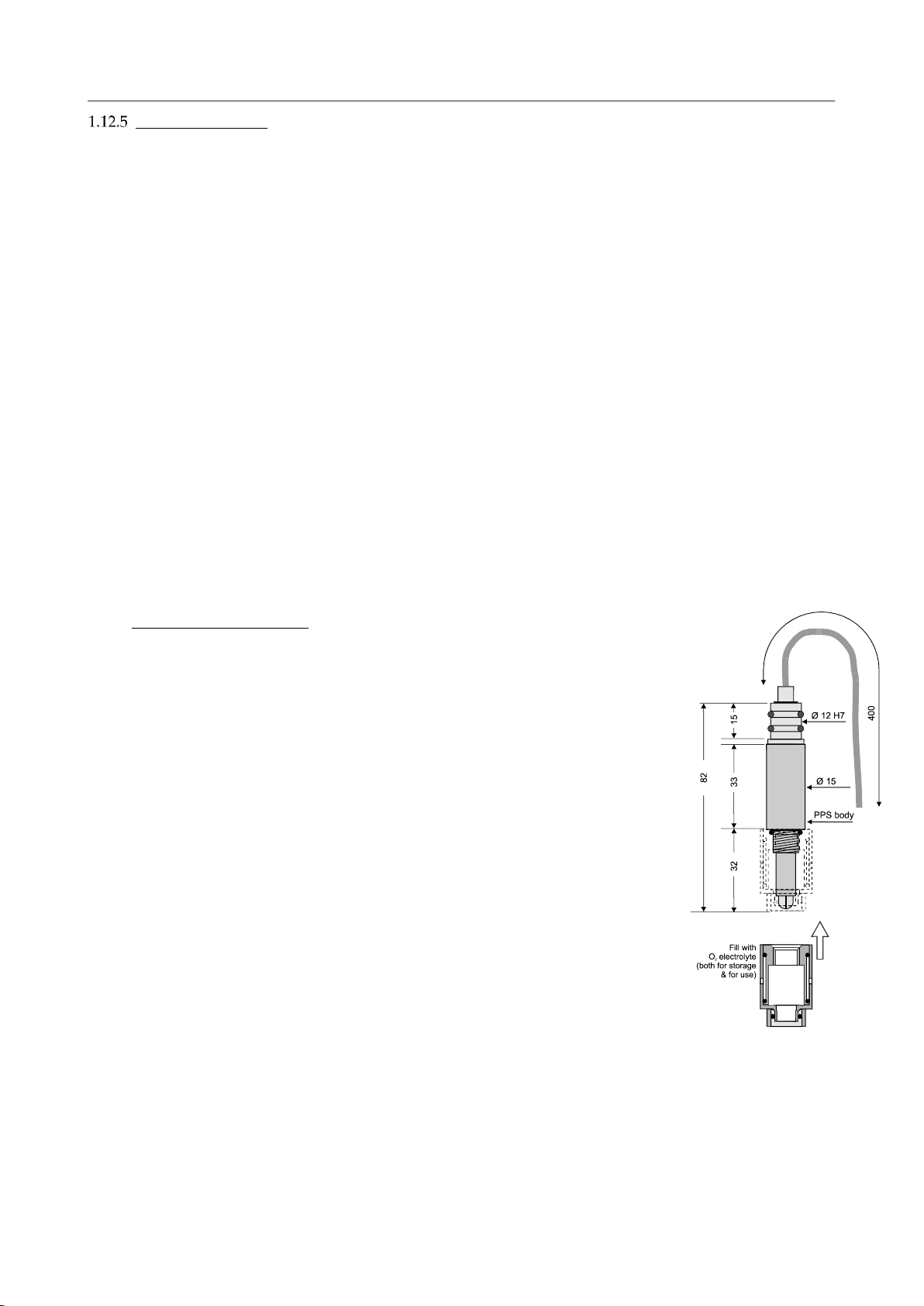
The oxygen sensor
The oxygen sensor is of the polarographic type and consists of two half-cells, the anode and the cathode.
The anode is a silver tube inside the sensor, which encircles a glass body where a platinum wire, forming
the cathode, is sealed. The platinum wire (cathode) ends at the tip of the sensor where the glass body is
rounded. A special membrane cap with a gas-permeable replaceable membrane screws onto the sensor.
The inside of the cap is filled with a special electrolyte which allows the current (measuring) to flow
between the anode and the cathode. The membrane is shielded from accidental bumps by a protective
ring. The anode acts as a reference cell, providing a constant potential with respect to the cathode. The
cathode, where oxygen is consumed or reduced, is separated from the sample to be analysed by a thin
layer of electrolyte and a special composite membrane. The electrolyte permits the chemical reaction to
occur whereas the membrane constitutes a barrier against ions and other substances. By applying a
polarizing voltage to the half-cells, the sensor develops a current proportional to the concentration of
oxygen in the sample in front of the cathode. Oxygen from the sample is drawn across the membrane,
at the sensor tip, in the area of the cathode. The applied polarization voltage is such that the sensor only
responds to oxygen. The sensor is insensitive to nitrogen, nitrous oxide, carbon dioxide and other gases.
To avoid stray ground current leaks, in case of membrane leaks, the anode is kept at ground potential
while the cathode is polarized at a fixed negative voltage. The oxygen sensor limits stirring effects on
the measurement and reads at least 97% of the true value, even with a stagnant aqueous sample. This is
because the very small cathode area and special cathode geometry, associated with a unique composite
membrane, minimize the consumption of the oxygen contained in the sample in contact with the
membrane. The function of this sensor depends on the reduction of oxygen at the cathode, as expressed
by the formula: O2+ 2 H2O + 4e->>> 4 OH-
The developed electrons represent the measuring current and are supplied by the silver/silver chloride anode.
Standard version, 150 bar
Type: polarographic with Pt/Ir cathode and
Ag(99.99%) anode.
Measurement range: 0... 50 ppm 0… 500% sat.
Accuracy: 0.1 ppm 1 % sat.
Resolution: 0.01 ppm 0.1% sat.
Polarization voltage: 650 mV DC.
Response time: 3s (green membrane @20°C)
0.9 s (blue membrane @20°C)
Max Pressure: 150 bar.
Sensor body: plastic and titanium.
Compensation: automatic compensation of pressure and
thermal variations.
Life: 2 years if intensively used to perform
continuous monitoring, up to 4 years if
used weekly to perform daily profiling or
monitoring.
Calibration frequency: weekly.
Maintenance: measuring membrane replacement,
electrolyte replacement
SECTION ONE –SYSTEM DESCRIPTION
IDRONAUT –Brugherio (MB) OCEAN SEVEN 314 On-line module 04-2019
7
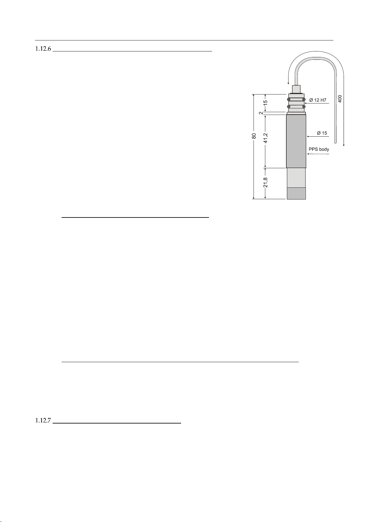
The oxygen sensor maintenance-free version - 5 bar only
Type: polarographic with Pt/Ir cathode
and Ag(99.99%) anode
Measurement range: 0... 50 ppm 0… 500% sat.
Accuracy: 0.1 ppm 1 % sat.
Resolution: 0.01 ppm 0.1% sat.
Polarization voltage: 650 mV DC
Response time: 30 s (membrane @ 20°C)
Max Pressure: 5 bar
Sensor body: black plastic (PPS)
Compensation: automatic compensation of
pressure and thermal variations.
Life: 2 years if intensively used to
perform continuous monitoring,
up to 4 years if used weekly to
perform daily profiling or
monitoring.
Calibration frequency: weekly.
Maintenance: maintenance free.
1.12.6.1 Polarographic Oxygen sensor measurement priming
The OCEAN SEVEN 314 allows the operator to obtain the oxygen data either expressed in ppm or %
Saturation. The formula which connects these two functions is given as by:
ppm = Saturation x Solubility / 100
The relevant formulae for the computation of saturation and solubility can be found in the below
“Calculation” section. The oxygen sensor for practical purposes is normally calibrated in air. The
reading obtained during the calibration is defined as the 100% saturation value for that particular air
temperature. This reading will vary with both temperature (3% per °C) and to a lesser extent with
barometric pressure (about 1% every 10 mBar or 7.6 mmHg). For the above reason during calibration,
the temperature is also automatically recorded and used by the OCEAN SEVEN 314 to immediately
compensate the calibration sensor slope for the temperature effect. This operation is performed during
real-time acquisition as well. Although the effect of barometric change is much smaller, the OCEAN
SEVEN 314 allows the operator to manually enter a correction coefficient during the calibration
procedure.
1.12.6.2 Oxygen depletion / Stirring effect and/or Barometric pressure correction coefficients
The oxygen sensor, like all the oxygen polarographic Clark sensors, sometimes needs that one or more
correction coefficients be applied to the final readings to account for extraneous factors. The OCEAN
SEVEN 314 has been designed such that, the application of such correction factors by the operator is a
relatively straightforward procedure. The oxygen sensor calibration and the correction coefficient
calculation are both described in the “Sensors Calibration” section of this manual.
The Blue-cap optical dissolved oxygen sensor
Oxygen optical sensors work according to the principle of dynamic fluorescence quenching. The sensor
contains fluorescent dye that is excited by light of a certain wavelength. Depending on the amount of
oxygen molecules present, the luminescence response of the optical sensor varies. A polymer fiber
transmits the excitation light of the sensor and at the same time also transmits the fluorescence response
of the sensor to the measurement device. The oxygen sensitive dye is immobilized in a polymer matrix.
This polymer can be applied to carrier material and used as sensor spots or sensor foil. It can also be
coated directly onto the optical fiber. Oxygen quenching luminophores have been studied from at least
SECTION ONE –SYSTEM DESCRIPTION
IDRONAUT –Brugherio (MB) OCEAN SEVEN 314 On-line module 04-2019
8
1939 when Kautsky described quenching of luminescence by oxygen. More recently, as optical sources,
detectors, and data processing have become more advanced, the application of luminophores to the
measurement of oxygen concentrations in liquids has resulted in bench-top instruments and optodes.,
with significant advances since 1990,s. Recent advances in blue light –emitting diodes and low-powers
high-speed electronics have enabled the miniaturization of oxygen sensitive optodes to the point of
field-deployable units. The sensors do not consume oxygen and are stable over long deployment period.
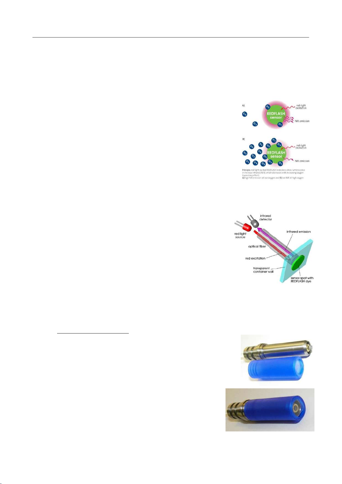
The new REDFLASH technology is based on the unique oxygen-sensitive REDFLASH dyes. In contrast
to common techniques using blue-light excitation, the REDFLASH dyes
are excitable with orange-red light and show and oxygen-dependent
luminescence in the near infrared (NIR). The REDFLASH technology
impresses by its high precision, high reliability, low power consumption,
low cross-sensitivity, and fast response time. The orange-red light
excitation significantly reduces interferences caused by auto-
fluorescence samples. Further, the NIR detection technology
significantly reduces interference with ambient light, known from the
old-blue-light techniques. The new REDFLASH technology is based on
the unique oxygen-sensitive REDFLASH indicator showing excellent
brightness. The measuring principle is based on the quenching of the
REDFLASH indicator luminescence caused by collision between oxygen
molecules and the REDFLASH indicator immobilized on the sensor tip or surface. The REDFLASH
indicators are excitable with the red light (More precisely orange-red at a wavelength of 610-630nm)
and show an oxygen-dependent luminescence in the near infrared (NIR 760-790 nm).
Principle: Red light exited the REDFLASH indicators show
luminescence in the near infrared, which decreases with the increasing
of oxygen (quenching effect). A) High NIR emission at low oxygen and
B) low NIR at high oxygen. The measuring principle is based on a
sinusoidal modulated red excitation light. This results in a phase-
shifted sinusoidal modulated emission in the NIR. The measurement
device measures this phase shift (termed dphi in the software) The
phase shift is then converted into oxygen units based on the Stem-
Vollmer-Theory. The red-light excitation significantly reduces
interferences caused by auto-fluorescence and reduces stress in the
biological systems. The REDFLASH indicators show much higher luminescence brightness than other
optical sensor working with blue light excitation. Further due to the excellent luminescence brightness
of the REDFLASH indicator, the actual sensor matrix can be now prepared much thinner, leading to
fast response times of the oxygen sensors.
1.12.7.1 BLUE CAP DESCRIPTION
The external par of the Blue Cap Oxygen Optical Sensor is a titanium
support with a 11,7mm diameter, where at its centre is placed a 3mm fiber
optics well sealed to guarantee 700 bar operations. The length of the
support is about 44mm (without the Blue replaceable membrane cap
installed); two 2-12 Parker O-rings seal the support onto the OS314
housing. The measuring membrane cap is simply fitted inside the titanium
support till it stops and is provided with a friction system (groovers)
to prevent unwanted removal or accidental loss. The membrane cap
is made of blue plastic to better shield the external light and is very
similar to the Idronaut pH watering cap. The only difference is that
a hole at its bottom allows the factory installation of the glass
window on its inside. The black sensor spot which allow the oxygen
measurement is centrally placed on the outside of the glass window.
The other side of the optical fiber remains indie the ON-LINE MODULE housing and is fitted in a
unique miniaturized transducer whose optics and electronics transform the optical signal into RS485

SECTION ONE –SYSTEM DESCRIPTION
IDRONAUT –Brugherio (MB) OCEAN SEVEN 314 On-line module 04-2019
9
output.
1.12.7.2 SPECIFICATIONS
Measuring range: 0-250% O2 (0-45 mg/l)
Detection limit: 0.02% O2 (0.01 mg/l)
Resolution: 0.01% O2 (0.005 mg/l) at 1% O2
0.05% O2 (0.025 mg/l) at 100% O2
Accuracy: +-0.02% O2 (0.01 mg/l) at 1% O2
+-0.2% O2 (0.1 mg/l) at 100% O2
Temperature range: 0 to 50°C
Response time (t90) gas/water: sensor spot down to 5 s
No cross-sensitivity: pH 1-14, CH4; CO2, H2S, any ionic species
Cleaning procedures: 3 % H2O2, ethanol, soap solution
Storage time: >3 years in darkness at room temperature. A black cap is provided to
dark the blue cap membrane installed on the ON-LINE MODULE.
Please remove it before deploying the ON-LINE MODULE in water
and before carrying out the calibration.
Calibration: single point
Optical Isolation: the sensor spots are covered with a final black layer in order to
minimize influence of strong external illumination
pH and reference sensors
The measurement of pH in seawater demands high accuracy since seawater has a high ionic strength
and is weakly buffered. The pH range in the oceans is particularly restricted and, only in very special
cases, the observed values are outside the range of 7.8 and 8.4 pH and, in some seas, the range extends
from 6.5 to 9.0 pH. Some problems have always arisen from the use of traditional reference sensors with
porous diaphragms, when measuring the pH in seawater, in particular at pressures in excess of a few
bars, due to the high and variable junction potentials that are generated. The IDRONAUT reference
sensor is in contact with the unknown solution by means of a small hole in the glass tip. This minimizes
and stabilizes the junction potential between the inner gel electrolyte and the liquid to be measured. The
reference sensor is a Silver/Silver Chloride cell in a saturated potassium chloride solid gel and the sensor
head is made of titanium. It is also available a reference sensor specifically developed for long-term
monitoring of seawater where the internal cell is 0.7 mol NaCl. The glass body of the sensor is fitted
with a plastic hydrating cap filled with the IDRONAUT REFERENCE SENSOR STORAGE SOLUTION
based on 3-mol KCl (or NaCl) or, if not available, even with KCl saturated solution to avoid drying of
the gel when not in use. This cap must be removed before measurements. The pH sensor has a titanium
head, a glass body and a pH sensitive glass tip, which can withstand pressures up to 150 bar or even
700 bar (special version). During all periods of inactivity, the glass tip must be fitted with a white plastic
hydrating cap filled with the pH 7 Buffer Solution, or simply with clean water. This is to prevent the
pH-sensitive glass from dehydration, which slows down the sensor response. This cap must be
removed before measurements.
Table of contents
Other idronaut Control Unit manuals

Popular Control Unit manuals by other brands


FUEL MASTER
FUEL MASTER AIM 2 installation manual

M-system
M-system EtherCAT R30GECT1 instruction manual

Ubisys
Ubisys C4 quick start guide

Blue Giant
Blue Giant BLUE GENIUS SERIES Installation & owner's manual

Tews Technologies
Tews Technologies TCP872 user manual

SEW-Eurodrive
SEW-Eurodrive MOVIAXIS MXR manual


