Waterworks GUTH56 Instruction sheet

PRODUCT SUPPORT 800.927.2120 8am - 6pm EST
UNIVERSAL
1/2" THERMOSTATIC VALVE INSTALLATION GUIDELINES
Page 1 of 3
6.13.2014
These guidelines have been prepared for the professional contractor to aid in the installation of:
UNIVERSAL 1/2" THERMOSTATIC VALVE STYLE NO. GUTH56, GU56TH (UK)
All dimensions are based on original specification and are subject to change and variation.
Please consult your Design Associate for current specifications.
Style No. GUTH56†
Code No. GUSV56R
SPECIFICATIONS:
Fitting Hole Diameter Ø4-1/2" (Ø 114mm)*
Inlet/Outlet Connection
Size & Type:
1/2" Female NPT†
Recommended Water
Pressure:
45 psi (3 Bar)
Unrestricted Maximum
Flow Rate:
7gpm @ 45 psi
(26 L/min @ 3 Bar)
Valve Material: Wax Element
Water Pressure: 20 psi MIN - 80psi MAX
(1.4 Bar Min - 5.5 Bar Max)
* Ø4-1/2" (Ø 114mm) hole is required for servicing.
†UK Style No. GU56TH supplied with 4 BSP Adapters,
assembly required.
IMPORTANT:
¾To ensure this product is installed properly, you
must read and follow these guidelines.
¾The owner/user of this product must keep this
information for future reference.
¾This valve includes integrated service stops. Make
sure the tile guard is in place.
¾This valve features anti-scald protection. The risk of
scalding exists until the installer had properly
calibrated/adjusted the temperature setting during
final trim installation.
¾This product must be installed by a professional
licensed contractor.
¾Check local building and plumbing codes to ensure
that your installation conforms to all applicable
requirements. In the State of Massachusetts, all
installations must comply with the rules and
regulations set forth within 248 CMR.
¾Supply fittings are designed in accordance with
pressure and temperature ratings specified in ASME
A112.18.1/B125.
¾DO NOT APPLY DIRECT HEAT TO THE VALVE. Pre-
solder any connections to prevent damage to the
cartridge and service stop seals.
¾The trim should be on-site prior to rough in and
allows the installer to visualize the installation.
¾This thermostatic valve only mixes hot and cold
water and does not have volume control or shut off
capability. A diverter or wall valves (SOLD
SEPARATELY) control on/off/volume and must be
installed for each fitting that will have water flowing
to it. This valve cannot be used with a diverting tub
spout.
¾Insure that the hot and cold supply lines are
connected to the valve according to the markings
on the valve body: NO INVERSE CARTRIDGE IS
AVAILABLE.
¾Inspect this product to assure you have all parts
shown that are required for proper installation.
¾Check incoming water pressure.
¾If valve is going to remain unused for an extended
period of time (over 3 months), then the water to
the valve should be shut off (via service stops or
system control valve) and the volume control valves
should be opened to allow the water in the
thermostatic valve to evaporate. This is to keep the
cartridge from being exposed to stagnant or hard
water, which can cause the valve to malfunction.
¾It is recommended to flush the supply lines prior to
valve installation.
ROUGH-IN:
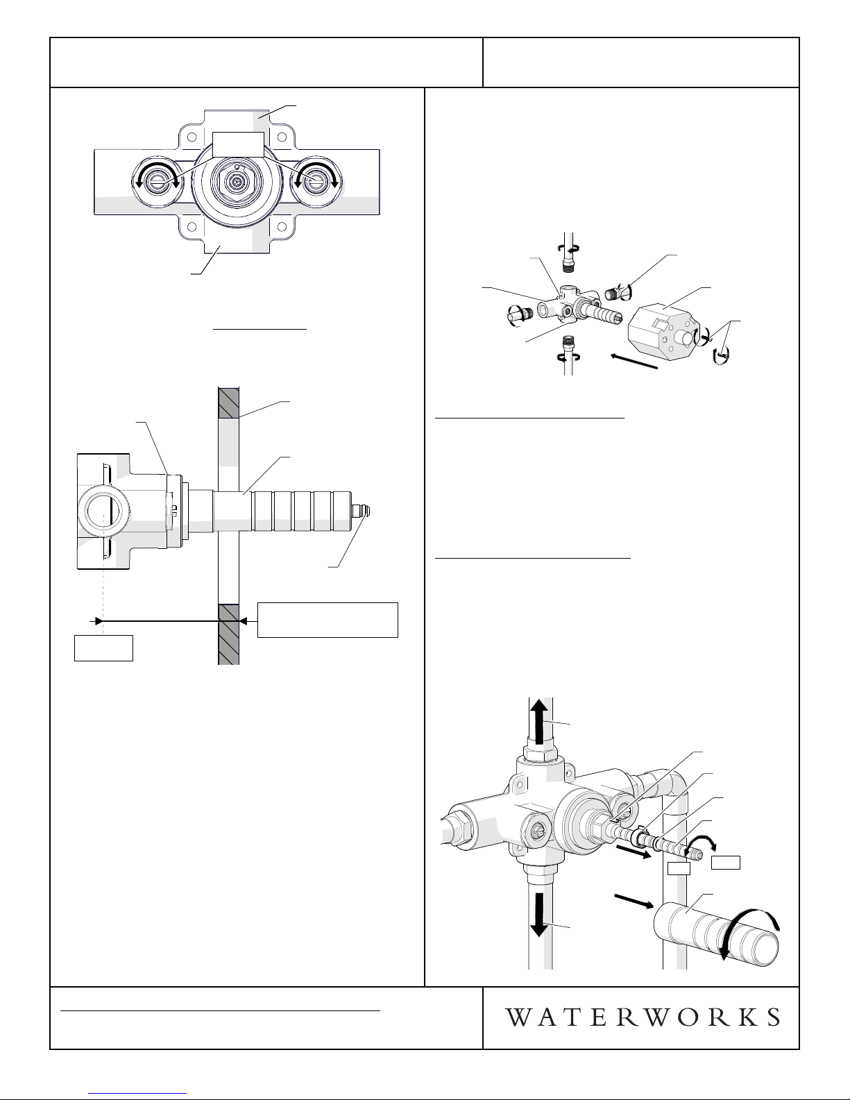
1. Remove TILE GUARD from VALVE BODY by
unthreading the SCREWS, as shown in Figure - 01.
VALVE
BODY
TILE
GUARD
SCREWS
VALVE
BODY
TILE
GUARD
SCREWS
FIGURE - 01
2. Make sure the valve body is positioned according to
valve markings so the inlets are situated with hot
piped on the left and cold piped on the right. Turn
the service stops to the right to close and to the left
to open. See Figure - 02.

PRODUCT SUPPORT 800.927.2120 8am - 6pm EST
UNIVERSAL
1/2" THERMOSTATIC VALVE INSTALLATION GUIDELINES
Page 2 of 3
6.13.2014
These guidelines have been prepared for the professional contractor to aid in the installation of:
UNIVERSAL 1/2" THERMOSTATIC VALVE STYLE NO. GUTH56, GU56TH (UK)
All dimensions are based on original specification and are subject to change and variation.
Please consult your Design Associate for current specifications.
7. The bottom port of the valve body is not plugged
and can be used to supply water to other fittings.
Install a 1/2" NPT plug (not supplied) if the port will
not be used.
8. Install the TILE GUARD to protect the valve during
the completion of the finished wall and to create the
exact opening for access to the service stops and
future servicing.
VALVE
BODY
1/2" MALE
NPT ADAPTER
Pre-Soldered to pipe.
(Not Supplied)
BOTTOM PORT
(Plug if not being used)
MOUNTING TAB
4X
TILE
GUARD
SCREWS
VALVE
BODY
1/2" MALE
NPT ADAPTER
Pre-Soldered to pipe.
(Not Supplied)
BOTTOM PORT
(Plug if not being used)
MOUNTING TAB
4X
TILE
GUARD
SCREWS
FIGURE - 04
INSPECT THE INSTALLATION:
9. Remove TILE GUARD and turn on water supply and
inspect all connections for leaks.
10. Turn off the water supply and turn off the SERVICE
STOPS, seen in Figure-02.
11. Reinstall TILE GUARD.
TEMPERATURE CALIBRATION:
¾The risk of scalding exists until the installer has
properly calibrated/adjusted the temperature
setting prior to final trim installation.
12. Remove the TILE GUARD and THREADED TUBE.
Slide the O-RING and LIMIT STOP up the
CARTRIDGE STEM. DO NOT REMOVE OR DAMAGE
THE O-RING. See Figure - 05.
OUTLET
TO VOLUME
CONTROL
OR DIVERTER
VALVE
(SOLD SEPARATELY)
OUTLET
TO VOLUME CONTROL
OR DIVERTER VALVE
(SOLD SEPARATELY) LIMIT STOP PIN
LIMIT STOP
O-RING
CARTRIDGE
STEM
THREADED
TUBE
OUTLET
TO VOLUME
CONTROL
OR DIVERTER
VALVE
(SOLD SEPARATELY)
OUTLET
TO VOLUME CONTROL
OR DIVERTER VALVE
(SOLD SEPARATELY) LIMIT STOP PIN
LIMIT STOP
O-RING
CARTRIDGE
STEM
THREADED
TUBE
HOT COLD
FIGURE - 05
TOP
OUTLET
BOTTOM
OUTLET
SERVICE
STOPS
TOP
OUTLET
BOTTOM
OUTLET
SERVICE
STOPS
CH
FIGURE - 02
3. IMPORTANT: Valve rough-in depth is measured
from the center of the inlets to the surface of the
finished wall and varies depending on the trim used.
See Figure - 03
VALVE
BODY
FINISHED
WALL
CARTRIDGE
STEM
THREADED
TUBE
VALVE
BODY
FINISHED
WALL
CARTRIDGE
STEM
THREADED
TUBE
ROUGH-IN DEPTH
3-1/4" MIN - 4-1/4" MAX
(83mm MIN - 108mm MAX)
CENTER
OF INLETS
FIGURE - 03
¾See Figure - 04 for steps 4-8.
4. Run 1/2" (15mm) copper supply lines to the proper
height of the valve inlets and be sure to secure all
piping and fittings.
¾Note: The valve body has 4 mounting tabs; 2 of
these tabs are used to hold the tile guard to the
valve body and the other 2 can be used to secure
the valve body to adequate blocking.
5. DO NOT APPLY DIRECT HEAT TO THE VALVE. Pre-
solder 1/2" male NPT adapters (not supplied) prior
to threading into the valve body.
6. For each fitting that will have water flowing to it,
install a wall valve or diverter valve (both sold
separately) at the same rough in depth and
according to the flow direction arrow marked on the
wall valve or diverter valve body.

PRODUCT SUPPORT 800.927.2120 8am - 6pm EST
UNIVERSAL
1/2" THERMOSTATIC VALVE INSTALLATION GUIDELINES
Page 3 of 3
6.13.2014
These guidelines have been prepared for the professional contractor to aid in the installation of:
UNIVERSAL 1/2" THERMOSTATIC VALVE STYLE NO. GUTH56, GU56TH (UK)
All dimensions are based on original specification and are subject to change and variation.
Please consult your Design Associate for current specifications.
¾See Figure - 05 & Figure - 06 for steps 13-16.
13. Turn on the water supply and a wall valve to run
water through the valve.
14. Slowly rotate the CARTRIDGE STEM clockwise to
attain full cold, then rotate it counterclockwise to
attain full hot. Verify that a full range of
temperatures exists. Note: It is approximately 3/4 of
a rotation from full cold to hot.
15. With the water running, rotate the CARTRIDGE
STEM to adjust the temperature to the MAXIMUM
desired bathing temperature, verified with a
thermometer. Note: It is not recommended to
exceed 110°F.
16. With the CARTRIDGE STEM at the maximum desired
bathing temperature, slide the LIMIT STOP back
onto the CARTRIDGE STEM, making sure that it is
making contact with the LIMIT STOP PIN. Slide the
O-RING back to its original position to prevent the
LIMIT STOP from sliding off the stem; then turn off
the water.
LIMIT STOP PIN
LIMIT STOP
O-RING
CARTRIDGE STEM
AT MAXIMUM DESIRED
HOT TEMPERATURE
LIMIT STOP PIN
LIMIT STOP
O-RING
CARTRIDGE STEM
AT MAXIMUM DESIRED
HOT TEMPERATURE
FIGURE - 06
INSPECT THE CALIBRATION & INSTALLATION:
17. Turn the CARTRIDGE STEM clockwise, then turn the
water on and confirm that the LIMIT STOP is
functioning properly by turning it counterclockwise
at which point it should hit the PIN and stop.
18. Verify the temperature to be the maximum
temperature set in Step 15. If it is not the correct
temperature, repeat the calibration process.
19. Reinstall the THREADED TUBE back onto the
VALVE BODY.
20. Reinstall the TILE GUARD using the SCREWS to
complete this installation.
¾If further assistance is required, please contact
Product Support at 1-800-927-2120 (8am-6pm EST).
¾See service part document for parts ordering,
available on WATERWORKS.COM.
†BSP Adapters can be ordered separately:
STYLE No. UNUK02
ITEM No. 45-57632-24328
Other Waterworks Control Unit manuals
Popular Control Unit manuals by other brands

Hitachi
Hitachi H Series instruction manual

Acromag
Acromag BusWorks 900MB Series user manual

Harman
Harman AMX HPX-AV102-MDP-R quick start guide

Texas
Texas TSW1100 quick start guide

RADIKAL TECHNOLOGIES
RADIKAL TECHNOLOGIES Swarm Oscillator RT-311 quick start guide

oventrop
oventrop Regudis W Installation and operating instructions