Motrona FM210 User manual

Operating Manual
motrona GmbH, Zeppelinstraße 16, DE - 78244 Gottmadingen, Tel. +49 (0) 7731 9332-0, Fax +49 (0) 7731 9332-30, [email protected], www.motrona.com
FM210
Frequency Multiplier, Frequency Divider
Product features:
•Adjustable Multiplier / divider (F1/F2)
•Input format RS-422, HTL single ended, HTL differential or TTL
•Multiplication / division without cumulative residual error
•Additional functions like Jog, Trim, Offset and Reference
•Input frequency up to 1MHz, depending on input format
•Output frequency max. 1MHz
•Two HTL outputs to display different states
•Supply 9 to 30 VDC

Fm210_01b_oi_e.docx / Nov-20 Page 2 / 40
Die deutsche Beschreibung ist verfügbar unter:
https://www.motrona.com/fileadmin/files/bedienungsanleitungen/Fm210_d.pdf
The English description is available at:
https://www.motrona.com/fileadmin/files/bedienungsanleitungen/Fm210_e.pdf
La description en français est disponible sur:
https://www.motrona.com/fileadmin/files/bedienungsanleitungen/Fm210_f.pdf
The operator software OS (freeware) is available at:
https://www.motrona.com/de/support/software.html
Version:
Description:
FM210_01b/AF/ Jul 2020
Version 1
Disclaimer:
All contents included in this manual are protected by the terms of use and copyrights of motrona GmbH. Any
reproduction, modification, usage or publication in other electronic and printed media as well as in the internet
requires prior written authorization by motrona GmbH.

Fm210_01b_oi_e.docx / Nov-20 Page 3 / 40
Table of Contents
Safety Instructions and Responsibility.....................................................................5
General Safety Instructions........................................................................................................ 5
Use according to the intended purpose ..................................................................................... 5
Installation ................................................................................................................................. 6
EMC Guidelines......................................................................................................................... 7
Cleaning, Maintenance and Service Notes................................................................................ 7
Introduction ................................................................................................................8
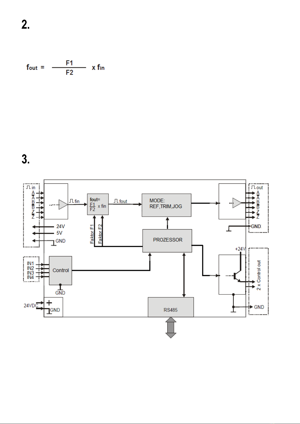
Block Diagram ............................................................................................................8
Electrical Connections...............................................................................................9
DC Input Voltage Supply ........................................................................................................... 9
Output for encoder supply 5V/24V Out ...................................................................................... 9
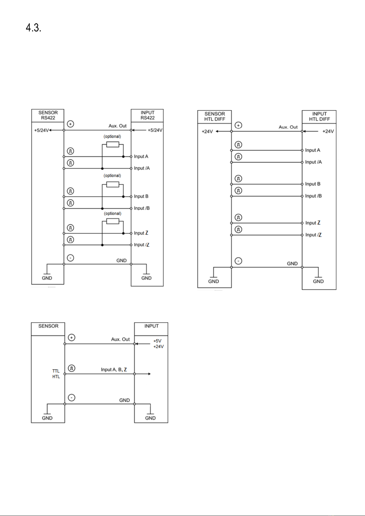
Encoder Inputs A, /A, B, /B, Z, /Z............................................................................................. 10
Control-Inputs INx.................................................................................................................... 11
Encoder Output A, /A, B, /B, Z, /Z............................................................................................ 11
Control Outputs OUTx ............................................................................................................. 11
LEDs........................................................................................................................................ 12
DIL Switch ............................................................................................................................... 12
USB ......................................................................................................................................... 12
RS-485 .................................................................................................................................... 12
Parameter..................................................................................................................13
Factor Menu............................................................................................................................. 13
Command Menu ...................................................................................................................... 13
General Menu.......................................................................................................................... 14
Input Menu............................................................................................................................... 15
Output Menu............................................................................................................................ 16
Modbus Menu.......................................................................................................................... 16
Serial Menu ............................................................................................................................. 17
Commissioning ........................................................................................................18
Setting the Encoder Mode ....................................................................................................... 18
Setting the Encoder Output...................................................................................................... 18
Setting the Factor Ratio ........................................................................................................... 18
Setting the Output Direction..................................................................................................... 18
Additional Optional Settings..................................................................................................... 19
6.5.1. Setting the Z Output Pulses............................................................................................................19
6.5.2. Setting the Serial RS-485 Interface ................................................................................................19
Input Functions ........................................................................................................20
Reset Static ............................................................................................................................. 20
Direction .................................................................................................................................. 20
Trim+/- ..................................................................................................................................... 21
Offset Edge.............................................................................................................................. 22
Reset Edge.............................................................................................................................. 22
Z Reference............................................................................................................................. 23
Inhibit....................................................................................................................................... 23
Jog........................................................................................................................................... 23
Prestop Mark ........................................................................................................................... 25
Edge Prestop........................................................................................................................... 26
Reference ................................................................................................................................ 26

Fm210_01b_oi_e.docx / Nov-20 Page 4 / 40
Output Functions......................................................................................................28
Encoder Error .......................................................................................................................... 28
Phase Error ............................................................................................................................. 28
Direction (f > 0) ........................................................................................................................ 28
Condition Reset Static ............................................................................................................. 28
Command Process Reference................................................................................................. 28
Command Process Jog ........................................................................................................... 28
Lecom Protocol ........................................................................................................29
Lecom Read ............................................................................................................................ 29
Lecom Write............................................................................................................................. 30
Modbus Protocol ......................................................................................................31
Modbus Read .......................................................................................................................... 31
Modbus Write........................................................................................................................... 32
Modbus CRC Calculation.........................................................................................35
Correction of the difference increments.................................................................35
Overshoot .................................................................................................................36
Parameter List ..........................................................................................................37
Dimensions...............................................................................................................39
Technical Specifications..........................................................................................40

Fm210_01b_oi_e.docx / Nov-20 Page 5 / 40
Safety Instructions and Responsibility
General Safety Instructions
This operation manual is a significant component of the unit and includes important rules and hints
about the installation, function and usage. Non-observance can result in damage and/or impairment
of the functions to the unit or the machine or even in injury to persons using the equipment!
Please read the following instructions carefully before operating the unit and observe all
safety and warning instructions! Keep the manual for later use.
A pertinent qualification of the respective staff is a fundamental requirement in order to use this
manual. The unit must be installed, connected and put into operation by a qualified electrician.
Liability exclusion: The manufacturer is not liable for personal injury and/or damage to property and
for consequential damage, due to incorrect handling, installation and operation. Further claims, due to
errors in the operation manual as well as misinterpretations are excluded from liability.
In addition, the manufacturer reserves the right to modify the hardware, software or operation manual
at any time and without prior notice. Therefore, there might be minor differences between the unit and
the descriptions in operation manual.
The raiser respectively positioner is exclusively responsible for the safety of the system and
equipment where the unit will be integrated.
During installation or maintenance all general and also all country- and application-specific safety
rules and standards must be observed.
If the unit is used in processes, where a failure or faulty operation could damage the system or injure
persons, appropriate precautions to avoid such consequences must be taken
Use according to the intended purpose
The unit is intended exclusively for use in industrial machines, constructions and systems. Non-
conforming usage does not correspond to the provisions and lies within the sole responsibility of the
user. The manufacturer is not liable for damages which has arisen through unsuitable and improper
use.
Please note that unit may only be installed in proper form and used in a technically perfect condition
(in accordance to the Technical Specifications, see chapter 16). The unit is not suitable for operation
in explosion-proof areas or areas which are excluded by the EN 61010-1 standard.

Fm210_01b_oi_e.docx / Nov-20 Page 6 / 40
Installation
The unit is only allowed to be installed and operated within the permissible temperature range. Please
ensure an adequate ventilation and avoid all direct contact between the unit and hot or aggressive
gases and liquids.
Before installation or maintenance, the unit must be disconnected from all voltage-sources. Further it
must be ensured that no danger can arise by touching the disconnected voltage-sources.
Units which are supplied by AC-voltages, must be connected exclusively by switches, respectively
circuit-breakers with the low voltage network. The switch or circuit-breaker must be placed as near as
possible to the unit and further indicated as separator.
Incoming as well as outgoing wires and wires for extra low voltages (ELV) must be separated from
dangerous electrical cables (SELV circuits) by using a double resp. increased isolation.
All selected wires and isolations must be conformed to the provided voltage- and temperature-ranges.
Further all country- and application-specific standards, which are relevant for structure, form and
quality of the wires, must be ensured. Indications about the permissible wire cross-sections for wiring
are described in the Technical Specifications (see chapter 16).
Before first start-up it must be ensured that all connections and wires are firmly seated and secured in
the screw terminals. All (inclusively unused) terminals must be fastened by turning the relevant
screws clockwise up to the stop.
Overvoltages at the connections must be limited to values in accordance to the overvoltage category
II.

Fm210_01b_oi_e.docx / Nov-20 Page 7 / 40
EMC Guidelines
All motrona units are designed to provide high protection against electromagnetic interference.
Nevertheless, you must minimize the influence of electromagnetic noise to the unit and all connected
cables.
Therefore, the following measures are mandatory for a successful installation and operation:
•Use shielded cables for all signal and control input and output lines.
•Cables for digital controls (digital I/O, relay outputs) must not exceed a length of 30 m and
are allowed for in building operation only
•Use shield connection clamps to connect the cable shields properly to earth
•The wiring of the common ground lines must be star-shaped and common ground must be
connected to earth at only one single point
•The unit should be mounted in a metal enclosure with sufficient distance to sources of
electromagnetic noise.
•Run signal and control cables apart from power lines and other cables emitting electromagnetic
noise.
Please also refer to motrona manual “General Rules for Cabling, Grounding, Cabinet Assembly”. You can
download that manual by the link
https://www.motrona.com/en/support/general-certificates.html
Cleaning, Maintenance and Service Notes
To clean the front of the unit please use only a slightly damp (not wet!), soft cloth. For the rear no
cleaning is necessary. For an unscheduled, individual cleaning of the rear the maintenance staff or
assembler is self-responsible.
During normal operation no maintenance is necessary. In case of unexpected problems, failures or
malfunctions the unit must be shipped for back to the manufacturer for checking, adjustment and
reparation (if necessary). Unauthorized opening and repairing can have negative effects or failures to
the protection-measures of the unit.

Fm210_01b_oi_e.docx / Nov-20 Page 8 / 40
Introduction
The FM210 is an intelligent unit for proportional conversion of an input frequency fin into an output
frequency fout.
The ratio results from setting two variable factors F1 (Parameter Factor 1) and F2 (Parameter Factor
2). Applications are mainly in the field of digital, frequency-controlled drives in the realization of
electronic shafts or electronically adjustable gears.
Since the pulse conversion works without errors, the unit can also be used for positioning tasks or
angular synchronous operation. Useful additional functions such as "Jog", "Reference", "Trim" and
"Offset" allow the slave drive to be moved independently of the master drive.
All settings are made at the DIL switches on the housing and by programming. The unit is housed in a
compact housing with screw terminals and can be plugged onto a top-hat rail.
Block Diagram

Fm210_01b_oi_e.docx / Nov-20 Page 9 / 40
Electrical Connections
The clamps should be tightened with a slotted screwdriver (blade width 2mm).
Please note that all inputs and outputs refer to the same ground potential
GND (except USB), which is also the negative pole of the unit supply.
In any case, it must be ensured that the signal quality of the entire
arrangement including the encoder, any external circuitry and cable
capacitance ensure a perfect pulse pattern at the unit input (pulse level,
pulse shape, phase offset A/B).
DC Input Voltage Supply
The unit is supplied with a DC voltage between 9 - 30 VDC via terminals 1 and 2 of X1.
The current consumption depends among others on the level of the supply voltage and the settings
and is approx. 45 mA at 24VDC without load from the encoder supply and outputs. All GND
connections are internally connected.
Output for encoder supply 5V/24V Out
At terminal 1 and 9 of X4, the auxiliary voltage for the encoder supply is +5.5 VDC and can be loaded
with max. 250mA. At terminals 1 and 8 of X4, the auxiliary voltage for the encoder supply
corresponds approximately to the voltage supply of the unit (at 24V supply at X1 approx. 23V) and
can be loaded with max. 250mA.

Fm210_01b_oi_e.docx / Nov-20 Page 10 / 40
Encoder Inputs A, /A, B, /B, Z, /Z
An encoder input A/B 90° for HTL/TTL/RS-422 signals is available at terminals 2 - 7 of X4. The
unused inputs must either remain open (HTL Single Ended as opposed to HTL Differential), or
possibly be terminated (unused Z-lines in RS-422 or HTL Differential Format).
Connection of the encoder inputs:
RS-422
HTL Differential
Other circuits (HTL-TTL single ended):

Fm210_01b_oi_e.docx / Nov-20 Page 11 / 40
Control-Inputs INx
4 control inputs with HTL PNP characteristics are available on terminal 2 –5 of X3.
Open control inputs are “low active”. The inputs could be used for control purposes. They could be
used for different functions regarding the parameterization.
Encoder Output A, /A, B, /B, Z, /Z
At the outputs of terminal X6, the encoder signals are available either in HTL or RS-422 format,
depending on the DIL switch S2/1 setting.
The output level corresponds in the HTL setting approximately to the supply voltage at X1.
(S2(1) = OFF, encoder output RS-422; S2(1) = ON, encoder output HTL)
Attention: If the DIL switch is set incorrectly, the following circuit may be
damaged.
Control Outputs OUTx
Two HTL (24V) signals are available at terminal 2 and 3 of X7. They can show different states
according to the parameterization.
At terminal 1 of X7, there is an analog test output which shows the status of the differential counter.
Here approx. 1.65V correspond to the counter value 0, the voltage range is max. 1.65V in both
directions and corresponds to approx. +/-128 increments. This output may only be connected to an
oscilloscope or a multimeter to record the timing behavior of the differential counter.

Fm210_01b_oi_e.docx / Nov-20 Page 12 / 40
LEDs
The green LED shows that the unit is ready (power supply switched on).
The yellow LED shows an input error in case of a static illumination. (only with RS-422 or HTL
differential), otherwise it flashes.
DIL Switch
The DIL switch S1 is used to detect an input error with HTL differential or RS-422 format. The A line
can be monitored via DIL1/1. If the DIL switch DIL1/1 is set to ON, the A line can give out an error.
The same applies to DIL switch DIL1/2 and the B line, as well as DIL1/3 and the Z line.
The DIL switch 2/1 is used to switch the voltage level of the encoder output at X6 from 5V (OFF) to
24V (ON). The DIL switch 2/3 is used for loading the factory parameters when the supply voltage is
switched on. In the ON position, the factory parameters will be loaded at the next power up and the
programmed values will be overwritten.
USB
The USB port can be used to connect to a PC. With the help of OS this interface can be used as a
programming interface. The ground isolated interface is configured as a virtual port and works with
the LECOM protocol with 115,2 kBaud, 8N1.
RS-485
An RS-485 (2-wire) interface is available at X5. Terminal 2 of X5 provides the non-inverted driver
output or input (A/Y), whereas terminal 3 provides the inverted driver output or input (B/Z).
This interface works with the LECOM protocol by default and can be switched to the MODBUS
protocol by parameter setting using the USB port and OS.

Fm210_01b_oi_e.docx / Nov-20 Page 13 / 40
Parameter
Factor Menu
Nr.
Parameter
Adjustment range
Default
000
Factor 1:
Proportional factor of the pulse ratio.
f out = (F1 x f in) / F2
0,0001 - 9,9999
1,0000
001
Factor 2:
Reciprocal factor of the pulse ratio.
f out = (F1 x f in) / F2
0,0001 - 9,9999
1,0000
002
Reserved
Command Menu
Nr.
Parameter
Adjustment range
Default
003
Ref. Speed High:
This parameter is only valid in Reference mode.
It indicates the frequency in Hz at high speed.
1 –1 000 000
4 000
004
Ref. Speed Low:
This parameter is only valid in Reference mode.
It indicates the frequency in Hz at low speed.
1 –1 000 000
2 000
005
Ref. Ramp:
This parameter is only valid in Reference mode.
It indicates the ramp time in seconds. (0 = ramp off).
0 - 99
10
006
Jog Speed:
This parameter is only valid in Jog mode.
It indicates the Jog frequency in Hz.
1 –1 000 000
1 000
007
Jog Ramp:
This parameter is only valid in Jog mode.
It indicates the ramp time in seconds. (0 = ramp off).
0 - 99
10
008
Trim Speed:
This parameter is only valid in Trim mode.
It indicates the duration in seconds for the inserted Trim pulses.
0,000 –5,000
0,020
009
Offset:
This parameter is only valid in Offset mode.
It indicates the number of increments to be added.
-99 999 –
99 999
200
010
Special Mode:
This parameter has different properties depending on the parameter
setting and extends the functionality.
0 - 5
0
011
Reserved
012
Reserved

Fm210_01b_oi_e.docx / Nov-20 Page 14 / 40
General Menu
Nr.
Parameter
Adjustment range
Default
013
Encoder Mode:
This parameter sets the input format of the encoder.
0 : Differential HTL
1 : RS-422
2 : HTL1 (Low 0…5V, High 9…30 V)
3 : HTL2 (Low 0…10V, High 14…30 V)
4 : TTL
0 –4
0
014
Z Pulse:
This parameter indicates the number of Z pulses at the output
0 –60 000
10
015
Sampling Time:
This parameter reflects the measuring time of the input frequency in
ms. The longer the measuring time, the more difference increments
are received during dynamic changes of the input frequency, since
the reaction time increases.
0,001 –1,000
1
016
Overshoot:
This parameter reflects the maximum frequency change in percent at
the output.
0 –100
10
017
Calculation Freq:
This parameter reflects different ways of calculating the output
frequency.
0 : faster, but less accurate
1 : slower, but more accurate
0 - 1
0
018
Direction:
This parameter changes the direction at output.
0 –1
0
019
Correction Basis:
This parameter reflects the closed loop control factor. Small values
can produce larger phase errors at higher frequencies. Larger values
can cause oscillations
0 : Regulation switched off
0 –10 000
25
020
Correction Freq:
This parameter in kHz corrects the phase error together with
parameter Correction Value.
0 : switched off
0 –1 000
0
021
Correction Value:
This parameter in kHz corrects the phase error together with
parameter Correction Freq.
0 : switched off
0 –10 000
0
022
Test:
This parameter activates the internal voltage measurements.
0 : Test off, faster
1 : Test on, slower
0 - 1
1
023
Reserved
024
Reserved

Fm210_01b_oi_e.docx / Nov-20 Page 15 / 40
Input Menu
Nr.
Parameter
Adjustment range
Default
025
Input 1 Config:
Defines the input behavior
0: Static Low, Function triggering at a "low" state
1: Static High, Function triggering at a "high" state
0 - 1
0
026
Input 1 Function:
0: No Function
1: Reset Edge
2: Inhibit
3: Direction
4: Jog
5: Offset Edge
6: Reference
7: Trim+
8: Trim-
9: Prestop Mark
10: Edge Prestop
11: Reset Static
12: Z Reference
0 - 12
0
027
Input 2 Config:
see Input 1 Config
0 - 1
0
028
Input 2 Function:
see Input 1 Function
0 - 12
0
029
Input 3 Config:
see Input 1 Config
0 - 1
0
030
Input 3 Function:
see Input 1 Function
0 - 12
0
031
Input 4 Config:
see Input 1 Config
0 - 1
0
032
Input 4 Function:
see Input 1 Function
0 - 12
0

Fm210_01b_oi_e.docx / Nov-20 Page 16 / 40
Output Menu
Nr.
Parameter
Adjustment range
Default
033
Output 1 Function:
0: No function
1: Encoder input error (only with input format RS-422 or
HTL differential)
2: Phase error (parameter Diff Error exceeded)
3: Fout > 0 (Direction recognition)
4: Reset activated
5: Reference activated
6: Jog activated
7: Encoder input error and phase error
(parameter Diff Error exceeded)
0 - 7
1
034
Output 2 Function:
see Output 1 Function
0 - 7
1
035
Output Polarity:
Switching the output polarity (binary)
0: no inversion of the outputs
1: OUT1 inverted, OUT2 not inverted
2: OUT1 not inverted, OU2 inverted
3: both outputs are inverted
0 - 3
0
036
Diff Error:
Number of differential counter increments at which the phase error is
activated for the outputs. With a setting of 50, a phase error is
triggered when the differential counter increments rise above 50 or
falls below -50.
0 - 99999
64
037
Reserved
Modbus Menu
Nr.
Parameter
Adjustment range
Default
038
Modbus Address:
Modbus address
1 - 247
1
039
Modbus CRC Reset:
Modbus CRC Calculator Reset
Additional tool, serves to calculate the CRC value
0 - 1
0
040
Modbus CRC Byte:
Modbus CRC Calculator Byte
Additional tool, serves to calculate the CRC value
0 - 255
0
041
Reserved

Fm210_01b_oi_e.docx / Nov-20 Page 17 / 40
Serial Menu
Nr.
Parameter
Adjustment range
Default
042
USB Unit No.:
USB unit number for the virtual port is fixed to 11.
11
11
043
USB Baud Rate:
USB baud rate for the virtual port is fixed at 115.2 kBaud.
0
0
044
USB Baud Rate:
USB format for the virtual port is fixed to 8N1.
0
0
045
Serial Page:
Selection of a specific variable page for internal diagnostics
0 - 7
0
046
Serial Mode:
Switching the RS-485 interface to different protocols, baud rates and
formats
0 : Lecom protocol with RS Unit No., Baud rate and format
1 : Modbus protocol with RS baud rate and 8E1
2 : Modbus protocol with RS baud rate and 8O1
3 : Modbus protocol with RS baud rate and 8N2
0 - 3
0
047
RS Unit No.:
Unit No. for the RS-485 interface (only for Lecom protocol)
11 - 99
11
043
RS Baud Rate:
RS Baud rate for the RS-485 interface
0 : 9600 Baud
1: 4800 Baud
2: 2400 Baud
3: 1200 Baud
4: 600 Baud
5: 19200 Baud
6: 38400 Baud
7: 56000 Baud
8: 57600 Baud
9: 76800 Baud
10: 115200 Baud
0 - 10
10
044
RS Format:
Format for the RS-485 interface
0 : 8N1 (8 data bit, non-parity, 1 stop bit)
1 : 8E1 (8 data bit, even parity, 1 stop bit)
2 : 8O1 (8 data bits, odd parity, 1 stop bit)
0 - 2
0
045
Reserved
046
Reserved

Fm210_01b_oi_e.docx / Nov-20 Page 18 / 40
Commissioning
Setting the Encoder Mode
First the parameter Encoder Mode must be selected for the connected encoder. For connection or
wiring see chapter Encoder Inputs. Depending on the selection of the encoder mode, an input error
can be detected on the input lines A, /A, B, /B or Z, /Z. (short circuit or possible line break depending
on termination).
The lines where an error should be detected can be selected by the DIL switch 1. An error can only
be detected in RS-422 or HTL differential format, all other formats do not trigger an error. If a Z line in
RS-422 format is not connected, the error triggering for the Z line must be deactivated by the DIL
switch S1. The error can be optionally shown by an output. The error is also indicated in the OS by
the output field Enc. Error (blue = error, white = no error).
Setting the Encoder Output
The encoder output can be changed from RS-422 (5V signals) to HTL (24 signals) using the DIL
switch S2. (S2(1) = OFF, encoder output RS-422; S2(1) = ON, encoder output HTL)
Attention: Wrong setting will destroy the following unit!
Setting the Factor Ratio
If the basic setting for both factors is 1:1, the parameter factor 1 is set to 1.0000, also the parameter
factor 2. The transmission behavior is best when both factors are approximately symmetrical to
1,0000. An example of a 10:1 ratio: F1 = 3.0000, F2 = 0.3000. It can thus be multiplied or divided.
If factor 1 decreases, the frequency at the output decreases.
If factor 1 increases, the frequency increases.
If factor 2 decreases, the frequency at the output increases.
If factor 2 increases, the frequency decreases.
Setting the Output Direction
The Direction parameter can be used to change the direction of the output signals A/B 90°.
The direction can also be switched by an input or by a serial command.
The direction information can be get out by an output.

Fm210_01b_oi_e.docx / Nov-20 Page 19 / 40
Additional Optional Settings
6.5.1. Setting the Z Output Pulses
The number of the Z output signals can be defined by the parameter Z Pulse. The Z output is set in
the high phase of the A and B signal.
The Z output pulses can be referenced by an input or by a command with the input Z pulses.
As long as the input or command is active, the internal Z counter is reset with every Z pulse and thus
referenced. If there are more Z input pulses than Z output pulses per time unit, then no Z pulse
appears as long as the command or input is active at the output. If there are more Z output pulses
than Z input pulses per time unit, then an asymmetrical Z pulse output image appears as long as the
command or input is active at the output.
6.5.2. Setting the Serial RS-485 Interface
The protocol of the RS-485 interface can be defined by the Serial Mode parameter. With the setting
Serial Mode = 0 the interface works with the Lecom protocol and with the parameter setting options
RS Unit No., RS Baud rate and RS Format. If the parameter Serial Mode is set to 1, 2 or 3 the
Modbus protocol is used, the baud rate remains adjustable via the parameter RS Baudrate, whereby
the format is set to 8 data bits, Parity Even (=1), Parity Odd (=2) or Parity None (=3) with 1 stop bit.
Various commands can be sent via Modbus or Lecom. The Modbus address can be set via the
parameter Modbus address. Furthermore, a Modbus CRC Calculator is available. (Parameter CRC
Reset and Byte).

Fm210_01b_oi_e.docx / Nov-20 Page 20 / 40
Input Functions
Reset Static
The Reset Static function sets the frequency output to 0Hz independent of the frequency input.
This function also resets the commands for Reference and Jog.
Triggering
Parameter
Comment
Addition
Input
Input X Config = 0/1
Input X Function = 11
If Input X Config = 0 is set, the command is
triggered in case of a "low" state at input X.
The status of the input can be
read in the OS Input field
Lecom
Code 54 (dec)
Release: 04 31 31 02 35 34 30 03 32
Set: 04 31 31 02 35 34 31 03 33
(Unit no. 11, command in hex)
If a 1 is written at code 54, the
command is set.
Modbus
FF02 (hex)
Release: 07 06 FF 02 00 00 18 78
Set: 07 06 FF 02 00 01 D9 B8
(Modbus address = 7, command in hex)
If a 1 is written to FF02, the
command is set.
If the Output X Function parameter is set to 4, the output reflects the command status.
(command set, output high without inversion)
Direction
The Direction function changes the direction of the frequency output.
Triggering
Parameter
Comment
Addition
Input
Input X Config = 0/1
Input X Function = 3
If Input X Config = 0 is set, the command is
triggered in case of a "low" state at input X.
The status of the input can be
read in the OS Input field
Lecom
Code 58 (dec)
Release: 04 31 31 02 35 38 30 03 3E
Set: 04 31 31 02 35 38 31 03 3F
(Unit no. 11, command in hex)
If a 1 is written at code 58, the
command is set.
Modbus
FF00 (hex)
Release: 07 06 FF 00 00 00 B9 B8
Set: 07 06 FF 00 00 01 78 78
(Modbus address = 7, command in hex)
If a 1 is written to FF00, the
command is set.
If the Output X Function parameter is set to 3, the output reflects the direction.
(frequency > 0, output high without inversion)
This command can be used together with other commands.
Table of contents
Other Motrona Media Converter manuals

Motrona
Motrona UZ210 User manual

Motrona
Motrona GV204 User manual

Motrona
Motrona GV210 User manual

Motrona
Motrona SV 210 User manual

Motrona
Motrona UF251 User manual

Motrona
Motrona IV 251 User manual

Motrona
Motrona SI 251 User manual

Motrona
Motrona ES001 User manual

Motrona
Motrona FP210 User manual

Motrona
Motrona IO220 User manual

Motrona
Motrona GV224 User manual

Motrona
Motrona PU 204 User manual

Motrona
Motrona IO221 User manual

Motrona
Motrona PU 210 User manual

Motrona
Motrona IP251 User manual

Motrona
Motrona IT210 User manual

Motrona
Motrona IT210 User manual

Motrona
Motrona IT251 User manual

Motrona
Motrona PU202 User manual

Motrona
Motrona SV211 User manual