IV25101A_e.DOC / Feb-08 Page 9 / 25
4. Commissioning
With basic applications, you can use the Teach procedure for commissioning of the unit.
Extended functions need a PC for setup and are described later.
4.1. Self Test:
Set all DIL switches according to your application and connect encoder and power supply to the
unit. Set switch position No. 6 to ON first (test mode) and power the unit up. The green LED
(power) and the yellow LED (status) must light both. After a successful self-test, the yellow LED
must switch off again (approx. 1 sec.)
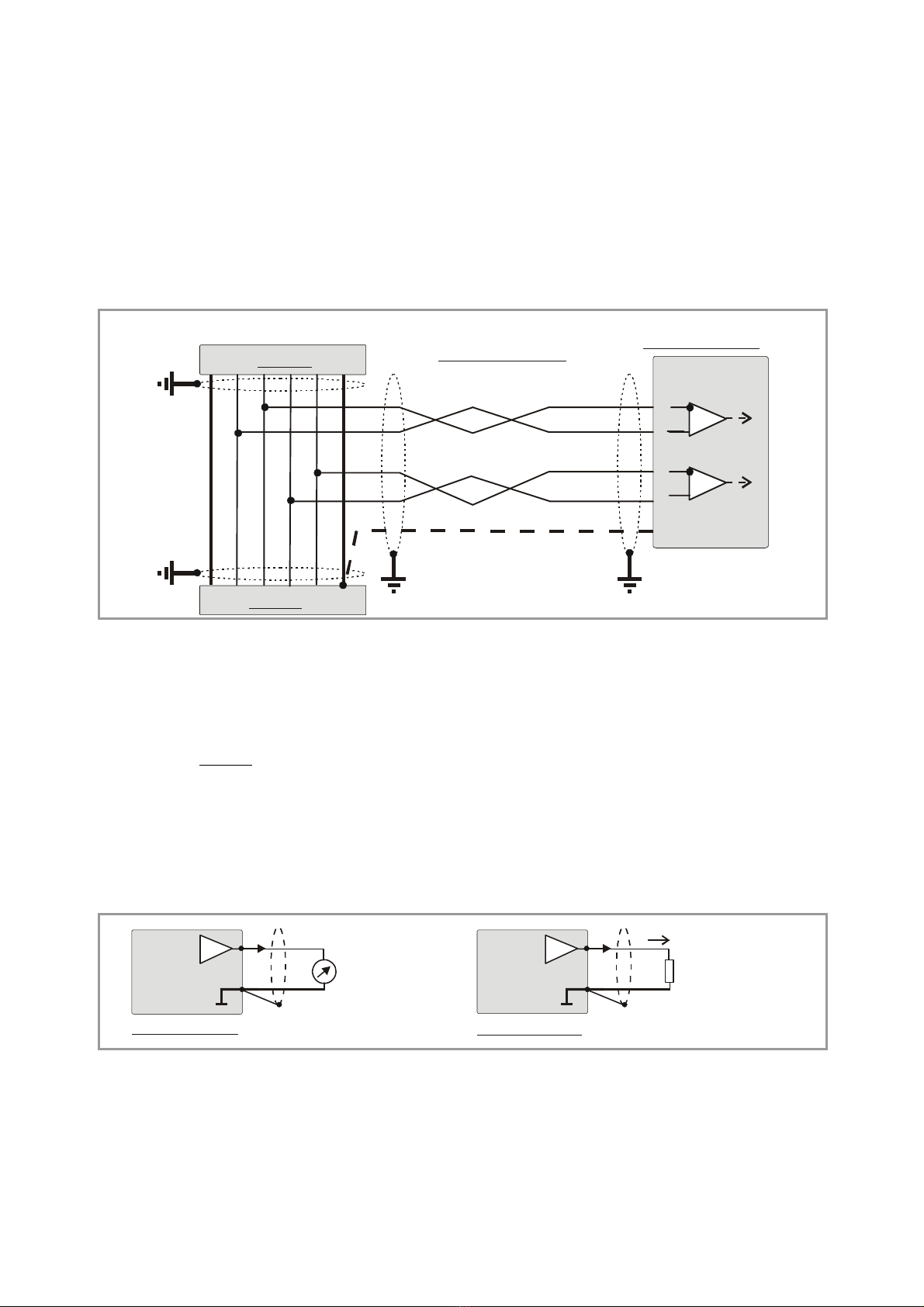
4.2. SSI signal test:
Push the Teach button one time now. This will verify the SSI Data lines. The yellow LED must
switch on. Where it remains off, you need to cross the input lines “Data+” (9) and “Data-“ (8).
The second actuation of the Teach button will test the SSI Clock lines in the same manner.
Again, the LED must be lit, otherwise you need to cross the lines “Clock+” (3) and “Clock-“ (2).*)
The third actuation of the Teach button will switch the LED off and conclude the test cycle.
Where you find your status LED lit after the first and the second actuation of the button, your
wiring of the encoder is o.k. Please power the unit down and set DIL position 6 to OFF for Teach
operation. With use of a PC and the OS32 operator software, you can check the status also
from the indicator boxes „Status SSI clock“ and „Status SSI data“ (red = status o.k.)
4.3. Scaling of the analogue output with use of the Teach function:
Power the unit up again, with DIL position 6 set to OFF. Press the Teach button one time.
The status LED will blink in a slow sequence now while the unit waits for the zero position.
Move your encoder to where you like zero output and press the button again.
This stores your zero definition and the LED will blink in a fast sequence now while the unit
waits for the full scale position. Move your encoder to where you desire full scale output and
press the button once more.
This stores your full scale definition and the LED will switch off. Your analogue output is now
set to the desired operating range, as selected by the output mode setting.
*) Testing the clock lines is primarily useful with Slave operation. Though the test works also in Master
mode, the result says only that the internal generation of the clock works fine. However, with Master
mode, this test cannot indicate faulty clock drivers or bad wiring of the clock lines.