IDX VL-2PLUS User manual
NO. XC09T0117
V1.0
Service Manual
2-Channel Sequential Quick Charger with AC Adaptor
VL-2PLUS
1. Introduction
2. Specifications
3. Safety precautions
4. Operating instructions
1. When used as a charger
2. When used as AC Adaptor
5. Features
6. Parts and their functions
7. Disassembly method
8. Drawings
1. General view
2. Details view
9. Schematics
1. FJ-3B charging board
10. Mounting layout
1. FJ-3B charging board
11. Wiring Diagram
12. Parts list
13. Packing Diagram
IDX Company, Ltd.
©2008-2009 IDX Company, Ltd.All right reserved. Unauthorized copying and distribution is a violation of

NO. XC09T0117
V1.0
WARNING
This service information is designed for experienced repair technicians only and is not designed for use by the general
public. It does not contain warning or cautions to advise non-technical individuals of potential dangers in attempting to
service a product. Products powered by electricity should be serviced or repaired only by experienced professional
technicians. Any attempt to service or repair the product or products dealt with in this service information by anyone
else could result in serious injuly or death.
1. Introduction
This service manual contains technical information which will allow service personnel to
understand and service the 2-Channel Sequential Quick Charger with AC Adaptor
VL-2PLUS.
If any part or circuit is changed or modified, this information will be followed by
supplementary service manual instructions which should be to be filed with this original
manual.
1
Model: VL-2PLUS IDX Company, Ltd.

NO. XC09T0117
V1.0
2. Specifications
Input Voltage : AC100V~240V AC 50/60Hz Automatic
Operating Temperature : -5ºC ~ 40ºC
Power Consumption : Max. 140VA
Compatible Batteries : All IDX ENDURASystem Li-Ion batteries
All IDX NP-type Li-Ion / Ni-Cd batteries via A-E2NP
Charge Adaptor
Charge method : Li-ion -> Constant Current / Constant Voltage
Ni-Cd -> Constant Current (-△V)
Quick Charge Current : All IDX ENDURA & NP-L type Li-ion batteries: 2.3A
All IDX Ni-Cd batteries: 1.9A
DC Output : Maximum output in AC operation
-> DC13.8V/ 4.3A (Max. 60W)
Charge Times Standard (When DC-OUT is not in operation)
ENDURA-ELITE: Approx. 290 min.
E-10 / E-10S :Approx. 220 min.
E-7 / E-7S : Approx. 180 min.
NP-L7 / NP-L7S :Approx. 180 min.
NP-23dx / NP-1dx: Approx. 80 min.
*All times are approximate and per battery, times will differ
according to a battery’s remaining capacity at time of charging.
Dimensions : 151 (W) x 79 (H) x 212 (D) mm
5.9 (W) x 3.1 (H) x 8.3 (D) inches
Weight : Approx. 950kg / 2.0 lbs.
2
Model: VL-2PLUS IDX Company, Ltd.

NO. XC09T0117
V1.0
3. Safety Precautions
- Do not attempt to open or modify this unit. All work should be carried out by IDX
authorized service personnel only.
- Use only with compatible batteries listed in this manual. Charging non-compatible
batteries may cause fire, electrical shock or other incidents.
- When connecting a battery be sure to connect the battery firmly.
- When in use do not place anything on the charger and do not block ventilation holes.
Usein a well ventilation area.
- Do not expose to, use or place the unit in direct sunlight, extreme dust, water or other
hazadous enviroments.
- During charging the temperature of the charger will rise, this is normal and not a
malfunction.
- A short between the plus(+) and minus (-) charge pins may cause fire, electrical shock
or other incidents. Make sure that the charge connector does not touch any metal parts
when a battery is not comnnected.
- For continued protection replace any fuses with specified type and rating.
- This unit contains no user serviceable parts.
- In case of fauilt or service, please contact your IDX dealer or appropriate IDX office.
- Confirm the connecting equipment specifications before use if the VL-2PLUS is used
as AC Adaptor. Use back up batteries which meet connecting equipment specifications
(capacity etc).
3
Model: VL-2PLUS IDX Company, Ltd.

NO. XC09T0117
V1.0
4. Operating Instructions
1. When used as a charger
A. Connect AC power cord firmly.
B. Turn the rear mounted power switch ON. (Power LED will light and show solid
Amber)
C. Basic Operation:
1. Connect a battery: “Battery Check Mode” starts, the charge channel LED will
show solid Red while the charger is checking the battery.
2. Battery Check: After 3 seconds the LED will remain Red indicating that the
VL-2PLUS is operating in quick charge mode, if a battery has a fault the LED will
flash Amber. If a battery cannot be recovered or is detected as over-charged, the
LED will flash Amber indicating a battery fault.
3. Charge Complete: When a battery has been fully charged, the charge channel
LED will automatically change to solid Green, indicating the battery is ready.
4. Remove the battery by pushing down either of the Release Levers located on
each channel. For NP-type battery removal, hold the charger to secure it and pull
the battery our straight.
2. When used as AC Adaptor
1. Connect the power cord firmly.
2. Turn the power ON. (Power LED will light and show solid Amber)
3. Power is supplied to the connected equipment by DC-OUT from the 4 pin XLR
output connector. (output voltage is 13.8V)
5. Features
- Can charge IDX ENDURA System Li-ion batteries. (All IDX NP-type Li-ion / Ni-Cd
batteries via optional A-E2NP Charge Adaptor)
- Quick charging on both channels sequentially.
- Built in 60W Camera Power Supply
- Auto safety & protection features for damaged or misused batteries.
- Robust light weight polycarbonate case. Recessed or power switch, built-inAC line
spare fuse, convenient carrying handle.
- Automatic Universal AC input for world-wide use.
- Can be operated in either horizontal or vertical position.
4
Model: VL-2PLUS IDX Company, Ltd.

NO. XC09T0117
V1.0
6. Parts and their functions
1DC Output DC power to a video camera or laptop editor is supplied
through this connector. Use the accessory DC cable to
connect it to the DC IN connector on the product to be
connected.
Pin Assign: Pin 1. GND Pin 2. N.C
Pin 3. N.C Pin 4. +13.8V
2 V-Mount Adaptor Mounts V-Mount type lithium ion battery
3Release Button Push to release the battery from mount
4Cooling Fan Cooling inside of the VL-2PLUS
5Power Switch Turns ON/OFF the power of VL-2PLUS
6AC Inlet This is the unit’s IEC power socket (3-pin). Use the
included accessory power cord to connect to at
AC120~240V power outlet.
2
3
7
1
4
6
5
5
Model: VL-2PLUS IDX Company, Ltd.

NO. XC09T0117
V1.0
7LED Indicator Light Off : No battery detected
Solid Amber : Charge Waiting
Solid Red : Battery Check / Quick charge / Battery
conditioning in progress
Solid Green : Charge Complete
Flashing Amber: Battery Fault
Flashing Red : Charger Fault
7. Disassembly Method
1. Removal of the Top cover
1. Remove the 4 rubber feet and then unscrew the 4 screws inside the feet.
2. Unclip the 2 lock-clip at the sides of the top cover carefully
6
Model: VL-2PLUS IDX Company, Ltd.
NO. XC09T0117
V1.0
7
Model: VL-2PLUS IDX Company, Ltd.
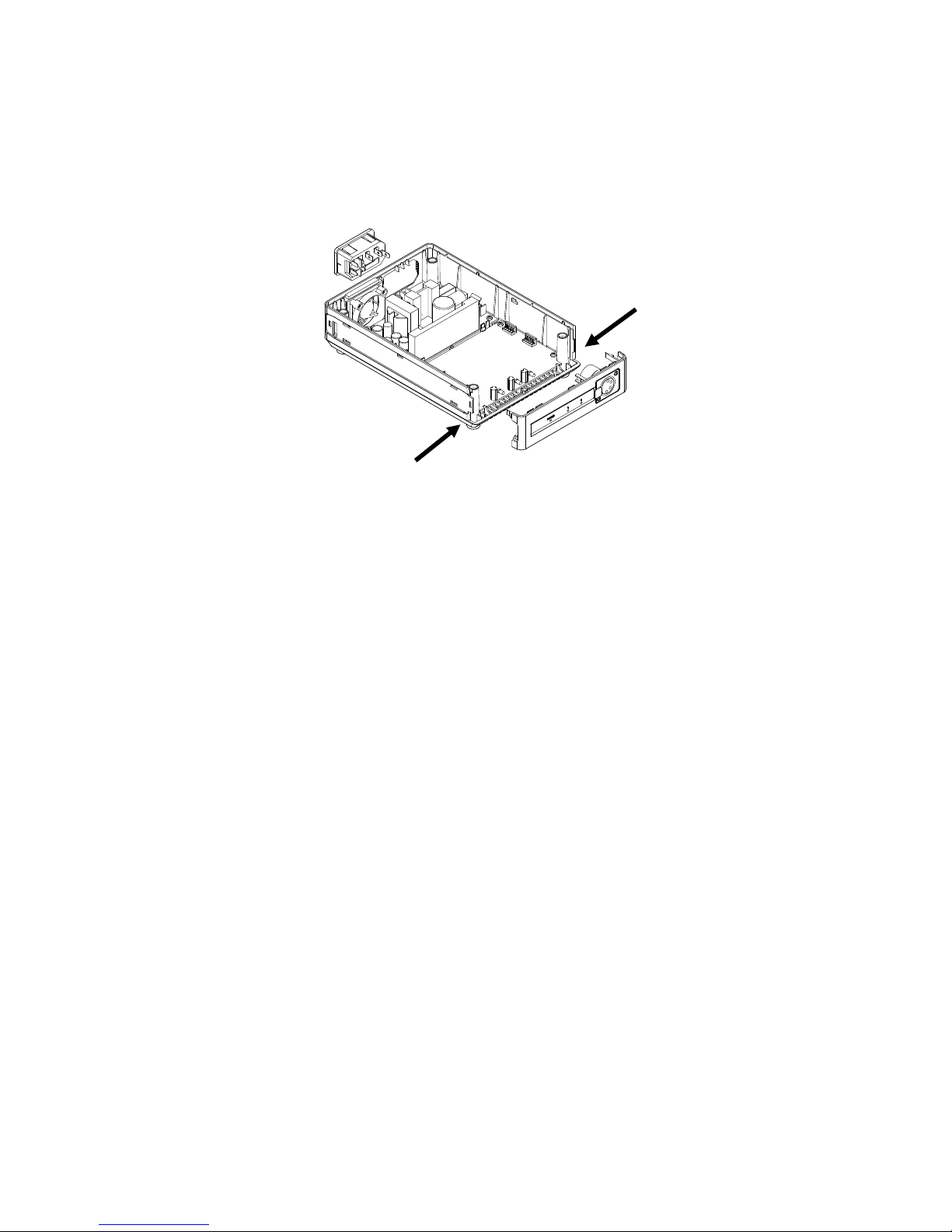
2. Removal of the Front panel
1. Unclip the 2 lock-clip at the sides of the front panel carefully
NOTE:
DO NOT USE THE PART NUMBER SHOWN ON THE FOLLOWING DRAWINGS FOR
ORDERING PARTS. THE CORRECT AND UPDATED PART NUMBER IS SHOWN IN THE
PARTS LISTS, AND MAY BE SLIGHTLY DIFFERENT OR AMENDED SINCE THESE
DRAWINGS WERE PREPARED.

NO. XC09T0117
V1.0
8
Model: VL-2PLUS IDX Company, Ltd.
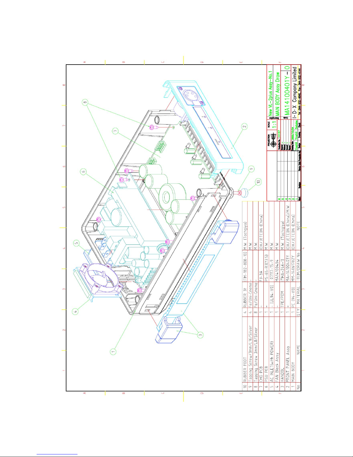
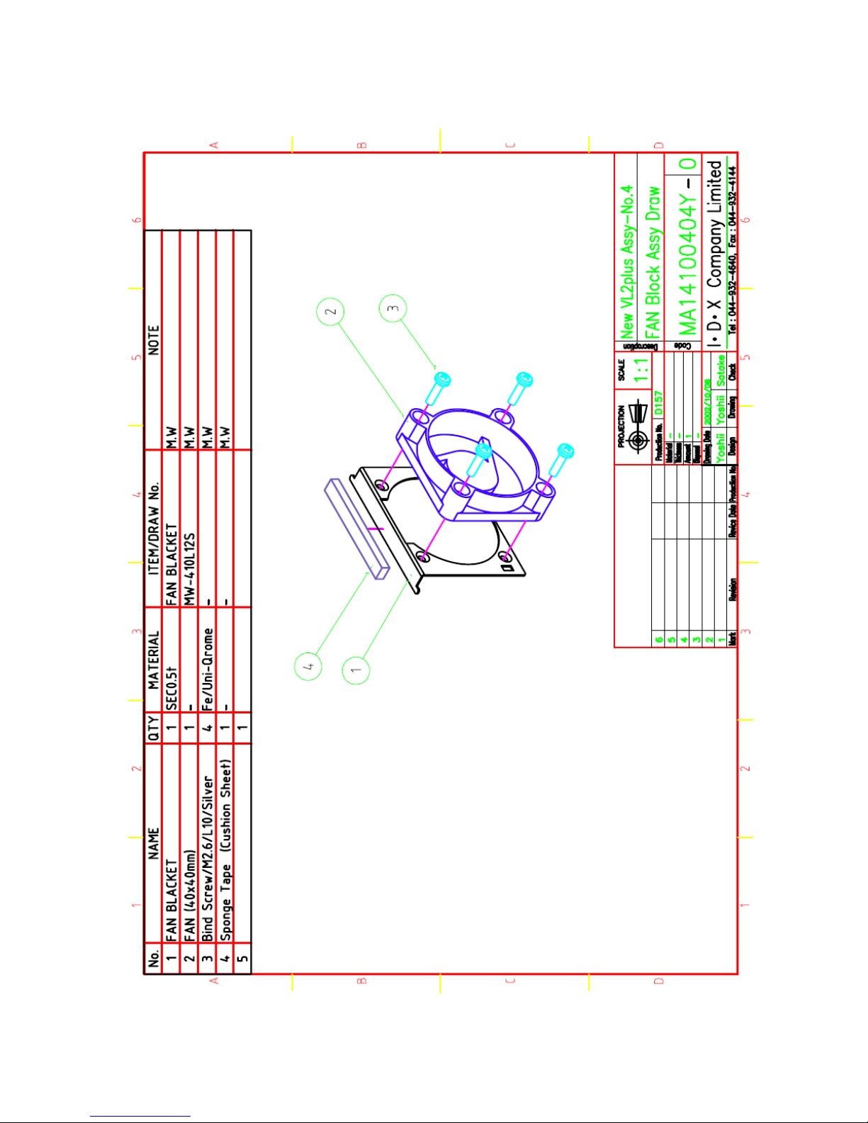
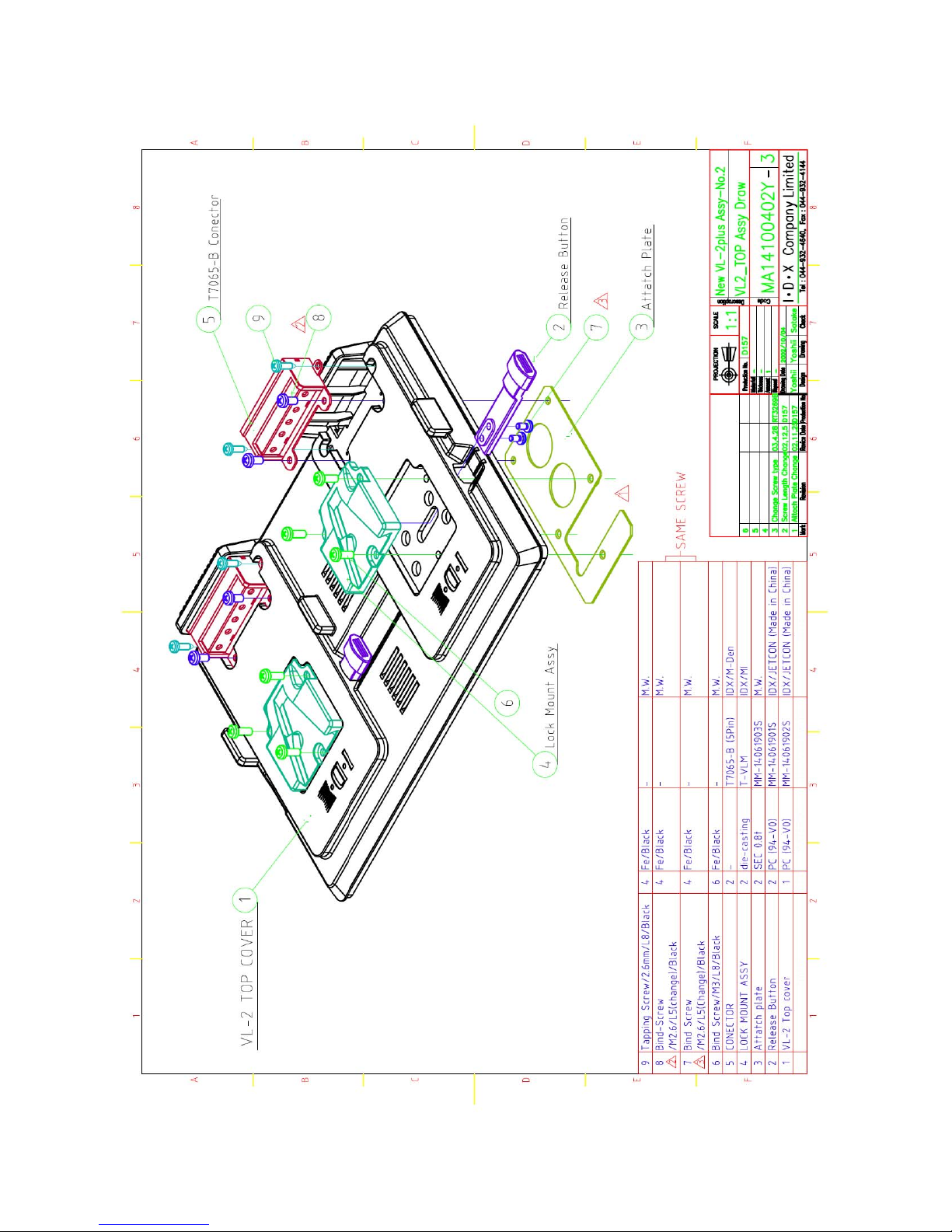
8. Drawing
1.GeneralView
NO. XC09T0117
V1.0
9
Model: VL-2PLUS IDX Company, Ltd.
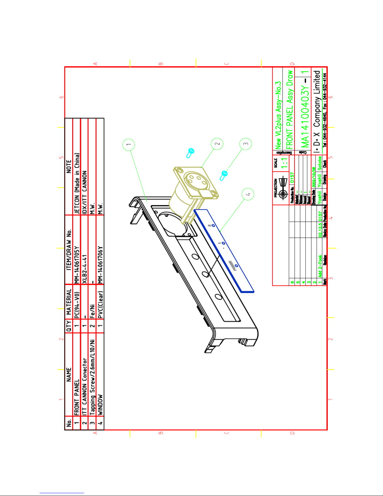
2. Details View
NO. XC09T0117
V1.0
10
Model: VL-2PLUS IDX Company, Ltd.
NO. XC09T0117
V1.0
11
Model: VL-2PLUS IDX Company, Ltd.
NO. XC09T0117
V1.0
12
Model: VL-2PLUS IDX Company, Ltd.

NO. XC09T0117
V1.0
13
Model: VL-2PLUS IDX Company, Ltd.
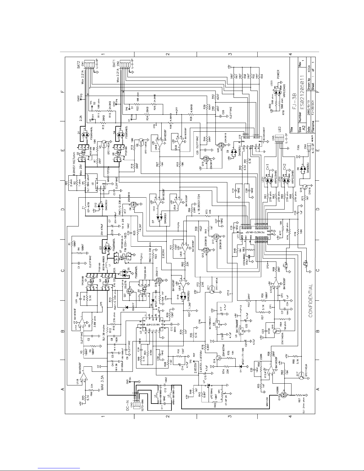
9. Schematics
Note:
1. Be sure to make any orders of replacement parts according to this list.
2. Unless otherwise specified, all resistors are in OHMS, K=1,000 OHMS,
all capacitors are in MICROFARADS(uF), P=uuF
3. The P.C. Board units marked with “ “ shown below the main assembled parts.
4. The parts marked with E on the exploded view show the electric parts.
5. IMPORTANT SAFETY NOTICE:
Components identified with the mark <!> have the special characteristics for safety. When replacing any of these components, use only the same
type.
6. The marking (RTL) indicates the retention time is limited for this item.
After the discontinuation of this assembly in production, it will no longer be
available.
NO. XC09T0117
V1.0
14
Model: VL-2PLUS IDX Company, Ltd.
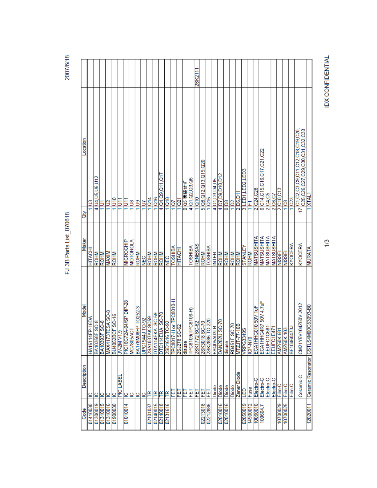
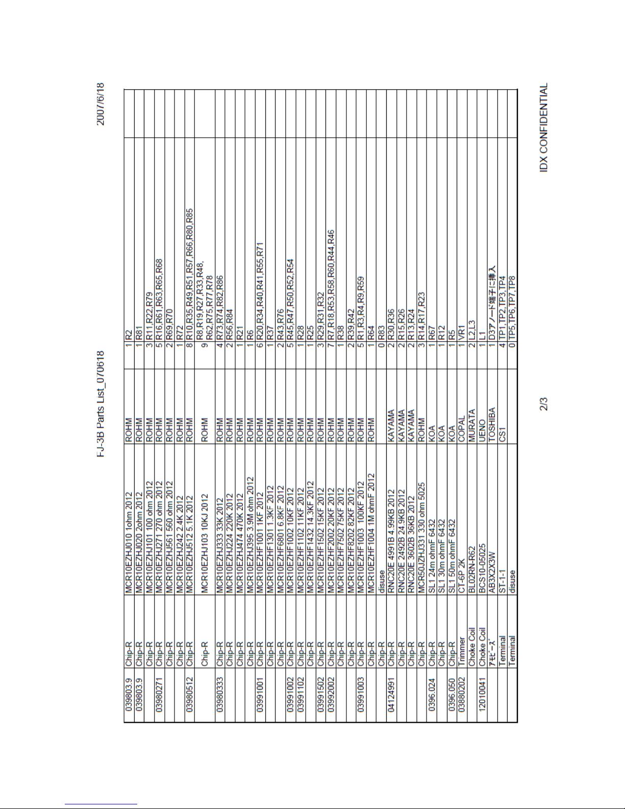
1. FJ-3B Charging Board
NO. XC09T0117
V1.0
15
Model: VL-2PLUS IDX Company, Ltd.
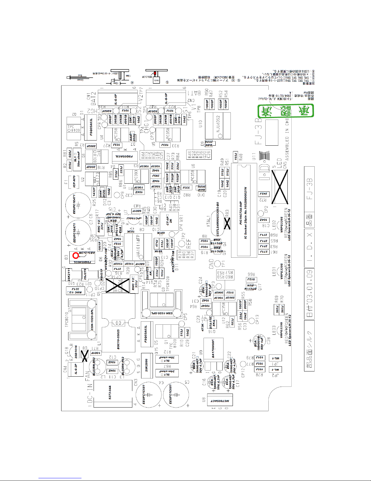
10. Mounting Layout
NO. XC09T0117
V1.0
16
Model: VL-2PLUS IDX Company, Ltd.
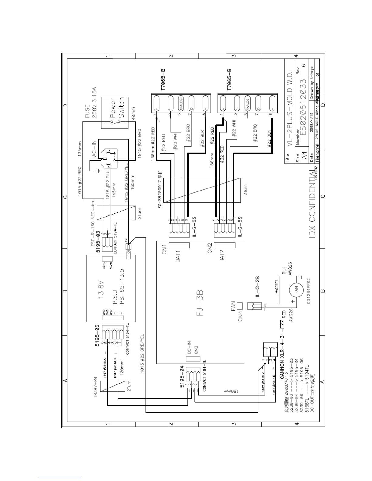
11. Wiring Diagram
NO. XC09T0117
V1.0
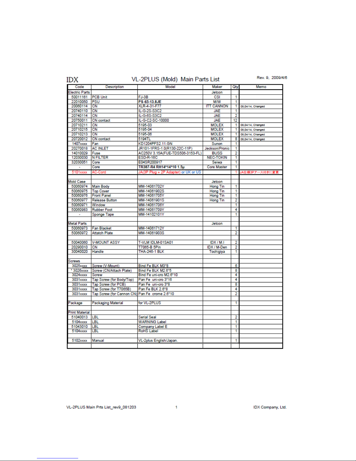
12. Parts list
1.GeneralParts
17
Model: VL-2PLUS IDX Company, Ltd.
NO. XC09T0117
V1.0
18
Model: VL-2PLUS IDX Company, Ltd.
2. FJ-3B Charging Board
NO. XC09T0117
V1.0
19
Model: VL-2PLUS IDX Company, Ltd.
Table of contents
Other IDX Batteries Charger manuals


